Table of Contents
Advertisement
SERVICE MANUAL
Ver. 1.1 2014.06
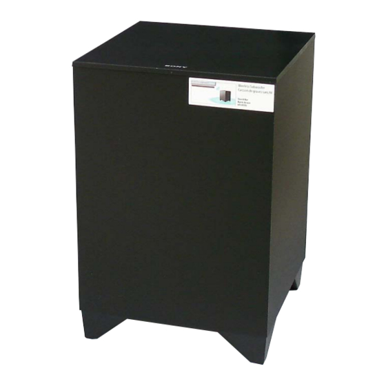
• SA-WCT770 is the active subwoofer in HT-CT770.
• All of the units included in the HT-CT770 (SA-WCT770/
SA-CT770) are required to confi rming operation of SA-
WCT770. Check in advance that you have all of the units.
• For the TEST MODE for this unit, refer to the service manual of HT-CT770.
9-893-983-02
Sony Corporation
2014F33-1
©
2014.06
Published by Sony Techno Create Corporation
SPECIFICATIONS
POWER OUTPUT (reference)
120 W (per channel at 4 ohms, 100 Hz) (Except Chinese model)
75W (per channel at 4 ohms, 100 Hz) (Chinese model)
Speaker system
Subwoofer system, Bass reflex
Speaker
160 mm (6 3/8 in) cone type
Rated impedance
4 ohms
Power requirements
120 V AC, 60 Hz (US and Canadian models)
220 V - 240 V AC, 50 Hz/60 Hz (AEP, UK, Australian, Chinese and Singapore models)
110 V - 240 V AC, 50 Hz/60 Hz (Saudi Arabia model)
120 V AC, 50 Hz/60 Hz (Taiwan model)
Power consumption
On: 30 W
Standby mode: 0.5 W or less
Dimensions (approx.) (w/h/d)
271 mm × 404 mm × 271 mm
(10 3/4 in × 16 in × 10 3/4 in)
Mass (approx.)
8.8 kg (17 Ib 10 1/2 oz)
Wireless receiver section
Speaker system
Wireless Sound Specification version 2.0
Frequency band
2.4 GHz (2.4000 GHz - 2.4835 GHz)
Modulation method
Pi / 4 DQPSK
Design and specifications are subject to change without notice.
SA-WCT770
Saudi Arabia Model
ACTIVE SUBWOOFER
US Model
Canadian Model
AEP Model
UK Model
Australian Model
Chinese Model
Singapore Model
Taiwan Model
Advertisement
Table of Contents

Related Manuals for Sony SA-WCT770


Summary of Contents for Sony SA-WCT770
- Page 1 Taiwan Model • SA-WCT770 is the active subwoofer in HT-CT770. • All of the units included in the HT-CT770 (SA-WCT770/ SA-CT770) are required to confi rming operation of SA- WCT770. Check in advance that you have all of the units.
- Page 2 Product includes software. © DTS, Inc. All Rights Reserved. Check leakage as described below. The BLUETOOTH® word mark and logos are registered trademarks owned by Bluetooth SIG, Inc. and any use of such marks by Sony Corporation is LEAKAGE TEST under license.
-
Page 3: Table Of Contents
SA-WCT770 TABLE OF CONTENTS SERVICING NOTES ..........DISASSEMBLY 2-1. Disassembly Flow ............2-2. Rear Panel Block ............2-3. Top Panel Block .............. 2-4. SUB LED Board ............. 2-5. Sub AMP Block .............. 2-6. Top Plate Block, Fuse (F900) ......... 2-7. POWER Board .............. -
Page 4: Servicing Notes
ADVANCE PREPARATION WHEN CONFIRMING OP- C936) to discharge the capacitor (C935 or C936). ERATION All of the units included in the HT-CT770 (SA-WCT770/SA- – POWER Board (Conductor Side) – CT770) are required to confi rming operation of SA-WCT770. Check in advance that you have all of the units. - Page 5 SA-WCT770 Ver. 1.1 MODEL IDENTIFICATION Distinguish by model number label printed on the rear plate of a main unit. Note: The printed contents of following fi gure model number label may be different from the model number label of a main unit.
-
Page 6: Disassembly
SA-WCT770 SECTION 2 DISASSEMBLY • This set can be disassembled in the order shown below. 2-1. DISASSEMBLY FLOW 2-2. REAR PANEL BLOCK 2-12. BOTTOM PANEL BLOCK (Page 6) (Page 13) 2-3. TOP PANEL BLOCK 2-13. LOUDSPEAKER (16 cm) (SP1) (Page 7) (Page 14) 2-5. -
Page 7: Top Panel Block
SA-WCT770 2-3. TOP PANEL BLOCK 3 All bosses are removed while moving jig in the direction of the arrow, and total four bosses top panel block is removed. 2 Insert the jig into a space and raise top panel block. -
Page 8: Sub Led Board
SA-WCT770 2-4. SUB LED BOARD 1 LED cover LED cover SUB LED board 2 two screws (BVTP2.6) 3 SUB LED board guide line front edge of the top panel LED cover SUB LED board front edge of the top panel LED cover is over the front edge of the top panel. -
Page 9: Top Plate Block, Fuse (F900)
SA-WCT770 Ver. 1.1 2-6. TOP PLATE BLOCK, FUSE (F900) 2 five screws 1 unweaved cushion hole (BV3) 2 eight screws 2 three screws (BV3) (BV3) ire e i guide line unweaved cushion 5 top plate block Note: When installing the top plate... -
Page 10: Power Cord (Ac1)
SA-WCT770 2-8. POWER CORD (AC1) wire holder wire holder 1 Remove the power cord from the clamp (L35). 2 power cord connector (CN900) clamp (L35) power cord SUB MAIN board power cord 3 Remove the power cord from two wire holders. -
Page 11: Rf Modulator (Swa12-4V Rx) (Rf1)
SA-WCT770 2-9. RF MODULATOR (SWA12-4V RX) (RF1) 4 flexible flat cable (24 core) Note 1: When installing the flexible flat cable (24 core), 2 screw (BV3) insert in the correct orientation after confirming the terminal face. 5 RF modulator (SWA12-4V RX) (RF1) 3 Remove the RF modulator block in the direction of the arrow. -
Page 12: 2-11. Sub Main Board
SA-WCT770 2-11. SUB MAIN BOARD coating clip 2 connector (CN114) 3 connector (CN111) connector connector (CN111) (CN114) SUB MAIN board 1 Remove two wires from the coating clip. – Sub AMP block rear view – 5 heatsink (main) Note: When installing the heatsink (main), spread the 4 two screws compound referring to “NOTE OF REPLACING... -
Page 13: 2-12. Bottom Panel Block
SA-WCT770 2-12. BOTTOM PANEL BLOCK 3 All bosses are removed while moving jig in the direction of the arrow, and bottom panel total six bosses block is removed. 2 Insert the jig into a space and raise bottom panel block. -
Page 14: Loudspeaker (16 Cm) (Sp1)
SA-WCT770 2-13. LOUDSPEAKER (16 cm) (SP1) Note 2: When installing the loudspeaker (16 cm) (SP1), make sure that there is a position of the speaker terminal to the position shown in the figure below. front side terminals position 1 four screws... -
Page 15: Troubleshooting
SA-WCT770 SECTION 3 TROUBLESHOOTING 1. ON/STANDBY lamp LED fl ashes in red (PROTECT) Note: When the volume level is “0”, power of amplifi er block is turned off, and amplifi er protect diagnosis is not performed. Set the volume level than “1”. -
Page 16: Diagrams
SA-WCT770 Ver. 1.1 SECTION 4 DIAGRAMS 4-1. BLOCK DIAGRAM RF MODULATOR STREAM PROCESSOR DIGITAL POWER AMP (SWA12-4V RX) IC105 IC104 L001 DOUT_RX 31 DATA OUTL1 6 PWM_A OUT_C L002 BCK0_RX 30 BCK (SUBWOOFER) OUTL2 PWM_B WCK0_RX 29 LRCK OUT_D MCK_OUT_RX... - Page 17 SA-WCT770 Ver. 1.1 THIS NOTE IS COMMON FOR PRINTED WIRING BOARDS AND SCHEMATIC DIAGRAMS. • Waveforms (In addition to this, the necessary note is printed in each block.) – SUB MAIN Board – For Printed Wiring Boards. For Schematic Diagrams.
-
Page 18: Printed Wiring Board - Sub Main Board (Side A)
SA-WCT770 Ver. 1.1 4-2. PRINTED WIRING BOARD - SUB MAIN Board (Side A) - • : Uses unleaded solder. SUB KEY (Page 24) >01P BOARD SUB MAIN BOARD (SIDE A) CN002 CL140 (NC) CN113 SL102 CN102 C178 (CHASSIS) CL137 C170... -
Page 19: Printed Wiring Board - Sub Main Board (Side B)
SA-WCT770 Ver. 1.1 4-3. PRINTED WIRING BOARD - SUB MAIN Board (Side B) - • : Uses unleaded solder. SUB MAIN BOARD (SIDE B) CL184 CL190 CL191 CL182 CL183 CL189 CL192 CL188 JL144 JL126 JL139 JL124 JL123 JL169 JL168 JL170... -
Page 20: Schematic Diagram - Sub Main Board (1/2)
SA-WCT770 4-4. SCHEMATIC DIAGRAM - SUB MAIN Board (1/2) - • See page 17 for Waveforms. • See page 25 for IC Block Diagrams. • See page 28 for IC Pin Function Description. SUB MAIN BOARD (1/2) SL102 CL140 JL125... -
Page 21: Schematic Diagram - Sub Main Board (2/2)
SA-WCT770 4-5. SCHEMATIC DIAGRAM - SUB MAIN Board (2/2) - • See page 17 for Waveforms. • See page 25 for IC Block Diagrams. SUB MAIN BOARD (2/2) CN114 CL181 CL180 >03S C199 R223 R225 JL157 C209 POWER CL179 BOARD... -
Page 22: Printed Wiring Board - Power Board
SA-WCT770 Ver. 1.1 4-6. PRINTED WIRING BOARD - POWER Board - • : Uses unleaded solder. POWER BOARD C903 (US, CND, TW) C907 A001 C904 (Except US, CND, TW) CL928 R923 Q920 R925 JS905 D923 JL904 EB902 EB901 D922 D920... -
Page 23: Schematic Diagram - Power Board
SA-WCT770 Ver. 1.1 4-7. SCHEMATIC DIAGRAM - POWER Board - • See page 25 for IC Block Diagrams. POWER BOARD EB901 (US, CND, TW) (Except US, CND, TW) C905 C906 0.001 470p (CHASSIS) 250V 250V F900 5A 125V (US, CND) -
Page 24: Printed Wiring Boards - Sub Led/Sub Key Boards
SA-WCT770 Ver. 1.1 4-8. PRINTED WIRING BOARDS - SUB LED/SUB KEY Boards - 4-9. SCHEMATIC DIAGRAM - SUB LED/SUB KEY Boards - • : Uses unleaded solder. SUB LED BOARD SUB MAIN >02P (Page 18) BOARD CN111 SUB LED BOARD... - Page 25 SA-WCT770 • IC Block Diagrams – SUB MAIN Board – IC101 PST8435UL IC103 TC74LCX74FT (EKJ) 13 12 11 GND 1 VREF – VDD 2 1 2 3 4 5 6 IC104 CXD9981TN GVDD_B /DTW UNDER- VOLTAGE INTERNAL PULLUP PROTECTION RESISTORS TO VREG PROTECTION TEMP.
- Page 26 SA-WCT770 IC105 CXD9843AR CLOCK CLOCK GENERATOR 36 XFSIIN GENERATOR (SECONDARY) (PRIMARY) XVSS 35 DVDD VSUBC 34 TEST 33 BFVSS VSSR OUTR2 32 BFVDD VDDR DATA OUTR1 FILTER & SAMPLING LINER GAIN S g P LOW CUT RATE INTERPOLATOR CONTROL VSSR...
- Page 27 SA-WCT770 Ver. 1.1 – POWER Board – IC910 STR-A6159M BUFFER – FEED OVER BACK SOURCE/OCP CURRENT PROTECTION BLANKING BURST DISCHARGE BIAS OFF TIMER LATCH OVER LOAD PROTECTION DRIVE OVER VOLTAGE PROTECTION DELAY LATCH THERMAL SHUTDOWN 6 NC 5 STARTUP INTERNAL...
- Page 28 SA-WCT770 • IC Pin Function Description SUB MAIN BOARD IC100 R5F212BASNFP (SYSTEM CONTROLLER) Pin No. Pin Name Description NO USE Not used S-AIR_DATA Two-way S-AIR data with the RF modulator FW_MODE Not used 4, 5 NO USE Not used System reset signal input terminal “L”: reset...
-
Page 29: Exploded Views
SA-WCT770 Ver. 1.1 SECTION 5 EXPLODED VIEWS Note: • -XX and -X mean standardized parts, so • Color Indication of Appearance Parts Ex- The components identifi ed by mark 0 they may have some difference from the ample: or dotted line with mark 0 are critical for original one. -
Page 30: Sub Amp Section
SA-WCT770 Ver. 1.1 5-2. SUB AMP SECTION not supplied not supplied not supplied not supplied not supplied not supplied not supplied not supplied not supplied not supplied not supplied FFC1 not supplied supplied not supplied not supplied supplied (Except US, CND) -
Page 31: Subwoofer Cabinet Section
SA-WCT770 Ver. 1.1 5-3. SUBWOOFER CABINET SECTION CAB1 Ref. No. Part No. Description Remark Ref. No. Part No. Description Remark 4-434-111-11 FOOT CAB1 A-1989-235-A SPEAKER (CABINET ASSY) 4-452-794-11 PANEL, BOTTOM (Including Speaker Wire) (Except US, CND) 4-245-976-01 SCREW (4X16) (TYPE1), +BVTP... -
Page 32: Electrical Parts List
SA-WCT770 Ver. 1.1 SECTION 6 POWER ELECTRICAL PARTS LIST Note: • Due to standardization, replacements in • CAPACITORS When indicating parts by reference num- the parts list may be different from the uF: μF ber, please include the board name. - Page 33 SA-WCT770 Ver. 1.1 POWER SUB KEY Ref. No. Part No. Description Remark Ref. No. Part No. Description Remark D950 8-719-080-53 DIODE RK36LF-B3 0 R924 1-249-401-91 CARBON 1/4W < FUSE HOLDER > 0 R925 1-216-829-91 METAL CHIP 4.7K 1/10W 0 R926...
- Page 34 < DIODE > C129 1-118-386-11 CERAMIC CHIP 0.1uF C130 1-118-386-11 CERAMIC CHIP 0.1uF D101 6-502-961-01 DIODE DA2J10100L D111 6-503-775-01 DIODE CRH02 (T5R, SONY, XM) C131 1-118-386-11 CERAMIC CHIP 0.1uF D112 6-502-966-01 DIODE DZ2J056M0L C132 1-118-386-11 CERAMIC CHIP 0.1uF C133 1-118-386-11 CERAMIC CHIP 0.1uF...
- Page 35 SA-WCT770 SUB MAIN Ref. No. Part No. Description Remark Ref. No. Part No. Description Remark IC101 6-715-382-01 IC PST8435UL R159 1-218-947-11 METAL CHIP 1/16W IC103 6-707-856-01 IC TC74LCX74FT (EKJ) R160 1-218-945-11 METAL CHIP 1/16W IC104 6-714-477-01 IC CXD9981TN (See Note)
- Page 36 SA-WCT770 Ver. 1.1 SUB MAIN Ref. No. Part No. Description Remark < COMPOSITION CIRCUIT BLOCK > RB002 1-234-372-11 RES, NETWORK 100 (1005X4) RB003 1-234-372-11 RES, NETWORK 100 (1005X4) < VIBRATOR > X100 1-795-375-11 VIBRATOR, CERAMIC (20 MHz) X101 1-814-590-11 QUARTZ CRYSTAL UNITS (49.152 MHz)
- Page 37 SA-WCT770 MEMO...
- Page 38 SA-WCT770 REVISION HISTORY Ver. Date Description of Revision 2014.02 2014.06 Addition of Chinese, Saudi Arabia, Singapore and Taiwan models Change of SUB KEY, SUB LED and SUB MAIN boards (Suffi x-12) Change of Part for Ref. No. R900 on the SUB LED board...