Table of Contents
Advertisement
Advertisement
Table of Contents

Related Manuals for AMT Datasouth Fastmark M7 Series


Summary of Contents for AMT Datasouth Fastmark M7 Series
- Page 1 Fastmark M7 Series Thermal Transfer Barcode Printer User’s Guide Document #120702...
-
Page 2: Table Of Contents
Contents 1. Introduction.....................4 1.1 Product Introduction ................4 1.2 Compliances .....................4 2. Operations Overview ..................6 2.1 Unpacking and Inspection ...............6 2.2 Printer Overview ..................7 2.2.1 Front View.....................7 2.2.2 Interior view ..................8 2.2.3 Rear View ...................10 2.3 Operator Controls................... 11 2.3.1 Front Panel Display ................11 2.3.2 LED Indicators ..................12 2.3.3 Front Panel Keys ................12 2.4 Setting Up the Printer................12... - Page 3 Contents 3. Menu Function ....................32 3.1 Setup Menu Overview ................33 3.1.1 Printer Setup..................34 3.1.2 Sensor ....................41 3.1.3 Serial Comm..................49 3.1.4 Ethernet ....................52 3.2 File Manager....................55 3.2.1 File List ....................55 3.2.2 Avail. Memory ..................56 3.2.3 Del. All Files ..................56 3.3 Diagnostics .....................57 3.3.1 Print Config.
-
Page 4: Introduction
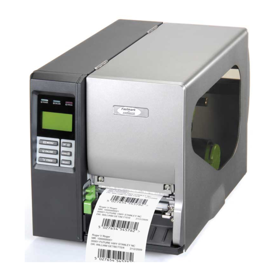
1. Introduction 1.1 Product Introduction Thank you very much for purchasing an AMT Datasouth bar code printer. This printer is designed with die-casting aluminum chassis and print mechanism, metal cover with large clear media view window, which ensuring to work for the extreme and heavy duty industrial environment and applications. - Page 5 ANSI C63.4:2003 CANADIAN ICES-003 C-Tick: AS/NZS CISPR22 (Class A) UL, CUL UL 60950 3 TÜV-GS: EN60950: 2000 Wichtige Sicherheits-Hinweise 1.Bitte lesen Sie Diese Hinweis sorgfältig durch 2.Heben Sie diese Anleitung fűr den späteren Gebrauch auf. 3.Vor jedem Reinigen ist das Gerät vom Stromentz zu trennen. Verwenden Sie Keine Flűssig-oder Aerosolreiniger.
-
Page 6: Operations Overview
2. Operations Overview 2.1 Unpacking and Inspection This printer has been specially packaged to withstand damage during shipping. Please carefully inspect the packaging and printer upon receiving the bar code printer. Please retain the packaging materials in case you need to reship the printer. Unpacking the printer, the following items are included in the carton. -
Page 7: Printer Overview
2.2 Printer Overview 2.2.1 Front View 1. LED indicators 2. LCD display 3. Front panel buttons 4. Paper exit chute 5. Lower front cover 6. Printer right side cover Page of 73... -
Page 8: Interior View
2.2.2 Interior view 1. Ribbon rewind spindle 2. Ribbon release button 3. Ribbon guide plate 4. Print head 5. Platen roller 6. Print head release lever 7. Media guide bar 8. Label roll guard 9. Label supply spindle 10. Ribbon supply spindle 11. - Page 9 16. Ribbon sensor 17. Media sensor Page of 73...
-
Page 10: Rear View
2.2.3 Rear View 1. Fan-fold paper entrance chute 2. Centronics interface 3. USB interface Note: 4. RS-232C interface 1. SD card slot, Ethernet interface and PS/2 interface are standard 5. Power jack socket interfaces for M7 PLUS models, but optional for M7 non-PLUS 6. -
Page 11: Operator Controls
2.3 Operator Controls 2.3.1 Front Panel Display LED indicators LCD display Front panel buttons Page of 73... -
Page 12: Led Indicators
2.3.2 LED Indicators Status Indication The printer power is turned off The printer power is turned on Printer is ready Pause Blinking Downloading data into printer. Printer is ready "CARRIAGE OPEN" or “CUTTER ERROR” Blinking "NO PAPER", "PAPER JAM" or "NO RIBBON" 2.3.3 Front Panel Keys Keys Function... -
Page 13: Installation Of Ribbon
2.5 Installation of Ribbon 2.5.1 Loading Ribbon 1. Lift open printer right side cover. 2. Push the print head release lever to open the print head mechanism. 3. Install the ribbon onto the ribbon supply spindle. Page of 73... - Page 14 4. Thread the ribbon through the ribbon sensor slot and then through the open space in between print head and platen. Ribbon Ribbon sensor 5. Wrap the ribbon onto the ribbon rewind spindle. Keeping the ribbon flat and without wrinkles. 6.
- Page 15 Loading path for ribbon Page of 73...
-
Page 16: Remove Used Ribbon
2.5.2 Remove Used Ribbon 1. Break the ribbon between ribbon guide plate and the ribbon rewind spindle. 2. Push the ribbon release button to release the ribbon on the ribbon rewind spindle. Page of 73... -
Page 17: Installation Of Media
3. Then, slide off the ribbon from ribbon rewind spindle. 2.6 Installation of Media 2.6.1 Loading Roll Labels 1. Lift open printer right side cover. 2. Push the print head release lever to open the print head mechanism. Page of 73... - Page 18 2. Move the label roll guard horizontally to the end of label spindle then flip down the label roll guard. 3. Place the roll of media on the label supply spindle. Flip up the label roll guard. Move the label roll guard horizontally to gently fit the width of label roll. Page of 73...
- Page 19 4. Pull label roll leading edge forward through the media guide bar, damper, media sensor and place the label leading edge onto the platen roller. Media sensor Media guide bar Internal rewind (Option) Media sensor Damper Label guide Page of 73...
- Page 20 6. Adjust the label guide to fit the width of the label. 7. Close the print head mechanism making sure the latches are engaged properly. 8. Using the front display panel, set the media sensor type and calibrate the selected sensor.
-
Page 21: Loading Fan-Fold Labels
2.6.2 Loading Fan-fold Labels Fan-fold media feeds through either the bottom or rear external label entrance chute. 1. Lift open printer right side cover. 2. Push the print head release lever to open the print head mechanism. 3. Insert the fan-fold media through the bottom or rear external label entrance chute. 4. - Page 22 Loading path for fan-fold labels Page of 73...
-
Page 23: Loading Media In Peel-Off Mode (Option)
2.6.3 Loading Media in Peel-off Mode (Option) 1. Lift open printer right side cover. 2. Push the print head release lever to open the print head mechanism. 3. Move the label roll guard horizontally to the end of label spindle then flip down the label roll guard. - Page 24 12. Lift up the peel-off roller release lever and close the print head mechanism. 13. Move the peel-off sensor toward the paper exit chute. Peel-off sensor 14. Peeling will automatically start. Press the FEED button to test. Liner Label Note: Please calibrate the gap/black mark sensor when changing media.
-
Page 25: Remove Liner From Internal Rewind (Option)
2.6.4 Remove Liner from Internal Rewind (Option) 1. Break the liner between peel-off roller and the internal rewind spindle. 2. Push the liner release button to release the liner on the internal rewind spindle. Page of 73... - Page 26 3. Then, slide off the liner from internal rewind spindle. Page of 73...
-
Page 27: Loading Media In Rewind Liner With Label Mode (Option)
2.6.5 Loading Media in Rewind Liner with Label Mode (Option) This mode can rewind the media including liner and label on the rewind spindle. 1. Lift open printer right side cover. 2. Insert the supply holder guide and paper core into the internal rewind for 1” core label roll. - Page 28 5. Insert another supply holder guide into the internal rewind for 1” core label roll. Supply holder guide 6. Using the LCD panel set the media sensor type and calibrate the selected sensor. (Please refer to section 3.1.2) Note: Please calibrate the gap/black mark sensor when changing media. Page of 73...
-
Page 29: Remove Labels From Internal Rewind (Option)
2.6.6 Remove Labels from Internal Rewind (Option) 1. Slide off the labels with supply holder guides from internal rewind spindle. Supply holder guides Page of 73... -
Page 30: Adjustment Knob
2.7 Adjustment Knob 2.7.1 Print head Pressure Adjustment Knob Print head pressure adjustment knobs The print head pressure adjustment knob has 5 levels of adjustment. Because the printer’s paper alignment is to the left side of mechanism, different media widths require different pressure to print correctly. - Page 31 The print head burn line adjustment knobs are used to fine tune the print quality for different thickness of media. Turning the knobs adjusts the print head’s burn line forward or backward as it relates to the platen roller. Caution: Incorrectly adjusting these knobs can lead to poor print quality and may cause damage to the printer.
-
Page 32: Menu Function
3. Menu Function Main Menu Overview Main Menu Setup F ile Manager Diagnostics Language Serv ice Exit ¡ õ ¡ õ ¡ õ ¡ õ ¡ õ Printer Setup File List Print Config. English Initialization ¡ õ ¡ õ ¡ õ ¡... -
Page 33: Setup Menu Overview
3.1 Setup Menu Overview Setup Printer Setup Sensor Serial Comm. Ethernet Exit ¡ õ ¡ õ ¡ õ ¡ õ TSPL2 Status Baud Rate Status ¡ õ ¡ õ ¡ õ ¡ õ Z PL2 Calibration Parity Configure ¡ õ ¡... -
Page 34: Printer Setup
3.1.1 Printer Setup Printer Setup TSPL2 Speed Density Direction Print Mode Offset Shift X Shift Y Reference X Reference Y Code Page Country Exit ¡ õ ¡ õ ¡ õ ¡ õ ¡ õ ¡ õ ¡ õ ¡ õ ¡... - Page 35 3.1.1.1 Speed: Print Setup 1/12 > Speed Speed Density Direction Use this option to setup print speed. The available print speed is between 4~12 ips and each increament/decreament is 1 ips. The default print speed is 6 ips. Press key to raise the print speed, and press key to decrease print speed.
- Page 36 The following 2 figures are the printouts of DIRECTION 0 and 1 for your reference. DIRECTION 0 DIRECTION 1 Note: If printing from enclosed software/driver, the software/driver will send out the command, which will overwrite the setting set from the front panel.
- Page 37 Cutter Batch Cut the label once at the end of the printing job. Note: If printing from enclosed software/driver, the software/driver will send out the command, which will overwrite the setting set from the front panel. 3.1.1.5 Offset: Print Setup 5/12 Direction Offset...
- Page 38 3.1.1.6 Reference X & Reference Y: Print Setup 9/12 Shift Y Reference Y Reference X > Reference Y This option is used to set the origin of printer coordinate system horizontally and vertically. Press the button to move the cursor from left digit to right digit, and press the button to set the value from “0”...
- Page 39 Windows Code Page (SBCS) Windows Code Page (DBCS) code page code page International International number number Character Set Character Set 1252 Latin 1 Traditional Chinese Big5 1250 Central Europe Simplified Chinese GBK 1253 Greek Japanese Shift-JIS 1254 Turkish Korean 1251 Cyrillic 1255 Hebrew...
- Page 40 Code Country Code Country Code Country Code Country Spanish United Brazil (Spain) Kingdom Canadian- English Hungarian Danish French (International) Spanish Yugoslavian Swedish Portuguese Dutch Italian Norwegian 358 Finnish Belgian Switzerland 048 Polish French Slovak German (France) Page of 73...
-
Page 41: Sensor
3.1.2 Sensor Sensor Status Calibration Exit 3.1.2.1 Status This function is available to check the printer’s sensor status. When enter the [Status] option, you will see following message. Paper Len. Gap Size Intensity Ref. Level 3.1.2.2 Calibration This option is used to set the media sensor type and calibrate the selected sensor. We recommend to calibrate the sensor before printing when changing the media. - Page 42 A. Gap Mode Calibration Gap Mode > Gap Mode > Automatic Bline Mode Manual Cont. Mode Pre-Printed Press the buttons to scroll the cursor to the media type and press button to enter the sensor calibration mode. Note: If printing from enclosed software/driver, the software/driver will send out the GAP or BLINE command, which will overwrite the sensor type setting set from the front panel.
- Page 43 2. Press the button to move the cursor from left digit to right digit, Gap Size and press the button to set the value from “0” to “9” and the “dot/ mm/ inch”. 0024 dot Press the button to set the gap size into the printer.
- Page 44 Gap Mode Manual > Pre-Printed Exit When enter [Pre-Printed] option, you will see following message. Please complete there steps 1. Press the button to move the cursor from left digit to right digit, and press the button to set Paper Len. the value from “0”...
- Page 45 B. Bline Mode Calibration Bline Mode Gap Mode > Automatic > Bline Mode Manual Cont. Mode Pre-Printed Press the buttons to scroll the cursor to the sensor type. Press the button to enter the black-mark sensor calibration mode. B-1 Automatic When enter the [Automatic] option, you will see following message and printer will feed the black mark label to calibrate the sensor sensitivity automatically.
- Page 46 3. Open the print head mechanism, put the black Bline Mode Mark under the media sensor. Press the Scan Mark button to set the value into the printer. Intensity Ref. Level Media sensor Black mark 4. Then, put the label without black mark under the Bline Mode media sensor.
- Page 47 B-3 Pre-Printed This function can set the paper length and gap size before auto-calibrate the sensor sensitivity. It can to get the sensor sensitivity accurately. Bline Mode Manual > Pre-Printed Exit When enter [Pre-Printed] option, you will see following message. Please complete there steps Press the button to move the cursor from...
- Page 48 C. Cont. Mode Calibration Cont. Mode Bline Mode > Automatic > Cont. Mode Manual Exit Exit Press the buttons to scroll the cursor to the sensor type. Press the button to enter the black-mark sensor calibration mode. C-1 Automatic When enter the [Automatic] option, you will see following message and printer will calibrate the sensor sensitivity automatically.
-
Page 49: Serial Comm
3. The sensor calibration is complete. Press Cont. Mode button the LCD screen will Complete return to the previous menu. Intensity Ref. Level 3.1.3 Serial Comm. Seria l Comm. Baud Ra te Parity Data Bits Stop Bit(s) Exit ¡ õ ¡... - Page 50 3.1.3.1 Baud Rate Serial Comm. Baud Rate > Baud Rate > 9600 bps Parity 19200 bps Data Bits 38400 bps This option is used to set the RS-232 baud rate. The default setting is 9600 bps. Press buttons to select the different baud rate and press button to set the value into printer.
- Page 51 3.1.3.4 Stop Bit Stop Bit(s) Serial Comm. Parity > Data Bits Exit > Stop Bit(s) This option is used to set the RS-232 Stop Bits. The default setting is “1” stop bit. Press buttons to select the different Stop Bits and press button to set the value into printer.
-
Page 52: Ethernet
3.1.4 Ethernet Use this menu to configure internal Ethernet configuration check the printer’s Ethernet module status, and reset the Ethernet module. This function is available on the LCD display when Ethernet card is installed. Press buttons to select the different options and press button to enter the option. - Page 53 3.1.4.1.2 MAC Ethernet Status > Status IP Address Configure > Exit Exit The MAC address information will be shown on the LCD display. Please press button to return to the previous menu. 3.1.4.2 Configure: (DHCP / Static IP) Use this menu to set the printer's DHCP and Static IP. 3.1.4.2.1 DHCP Configure Ethernet...
- Page 54 3.1.4.2.2 Static IP Use this menu to set the printer's IP address, subnet mask and gateway. Ethernet Configure Status DHCP > Configure > Static IP Exit Exit Press buttons to select the different options and press button to enter the option. Press key to cancel the setting and return to the previous menu.
-
Page 55: File Manager
3.2 File Manager This feature is used to check the printer available memory and file list. File Mana ger File List Avail. Memory Del. All Files Exit ¡ õ ¡ õ DRAM DRAM ¡ õ ¡ õ FLASH FLASH ¡ õ ¡... -
Page 56: Avail. Memory
3.2.2 Avail. Memory Use this menu to show available memory space. File Manager Avail. Memory File List DRAM: 256 KB > Avail. Memory FALSH: 6656 KB Del. All Files CARD: 0 KB 3.2.3 Del. All Files Use this menu to delete all files. Press button to delete all files in the device. -
Page 57: Diagnostics
3.3 Diagnostics Diagnostics Print Config. Dump Mod e Rotate Cutter Exit 3.3.1 Print Config. This feature is used to print current printer configuration to the label. On the sconfiguration printout, there is a print head test pattern, which is useful for checking if there is any dot damage on the print head heater element. -
Page 58: Dump Mode
3.3.2 Dump Mode Captures the data from the communications port and prints out the data received by printer. In the dump mode, all characters will be printed in 2 columns as following. The left side characters are received from your system and right side data are the corresponding hexadecimal value of the characters. -
Page 59: Rotate Cutter
3.3.3 Rotate Cutter In case paper is jammed in the cutter, this feature can rotate the cutter blade forward or reverse direction, which is helpful to remove the jammed paper easily from the cutter. Diagnostics Fwd. Print Config. DOWN: Rev. Dump Mode >... -
Page 60: Service
3.5 Service Service Initialization Mileage Info. Exit This feature is used to restore printer settings to defaults and display printer mileage information. 3.5.1 Initialization Service Initialization Initializing ... > Initialization Mileage Info. SELECT YES Exit MENU The printer settings are restored to defaults as below once printer is initialized. Note : When printer initialization is done, please calibrate the gap or black mark sensor before printing. -
Page 61: Mileage Info
Country code Clear flash memory Shift X Shift Y 3 (Will be reset. Need to re-calibrate the gap) Gap sensor sensitivity Bline sensor sensitivity 2 (Will be reset. Need to re-calibrate the gap) English Language DHCP IP address 3.5.2 Mileage Info. Use this option to check the printed mileage (displayed in meter). -
Page 62: Diagnostic Tool
4. Diagnostic Tool The Diagnostic Utility is a toolbox that allows users to explore the printer's settings and status; change printer settings; download graphics, fonts, and firmware; create printer bitmap fonts; and to send additional commands to the printer. Using this convenient tool, you can explore the printer status and settings and troubleshoot the printer. -
Page 63: Printer Function (Calibrate Sensor, Ethernet Setup, Rtc Setup
4.2 Printer Function (Calibrate sensor, Ethernet setup, RTC setup…) 1. Select the PC interface connected with bar code printer. 2. Click the “Function” button to setting. 3. The detail functions in the Printer Function Group are listed as below. Function Description Factory Default Initialize the printer and restore the settings to factory default. -
Page 64: Troubleshooting
5. Troubleshooting 5.1 Common Problems The following guide lists the most common problems that may be encountered when operating this bar code printer. If the printer still does not function after all suggested solutions have been invoked, please contact the Customer Service Department of your purchased reseller or distributor for assistance. - Page 65 * Re-connect cable to interface. * If using serial cable, - Please replace the cable with pin to pin connected. - Check the baud rate setting. The default baud rate setting of printer is 9600,n,8,1. * If using the Ethernet cable, - Check if the Ethernet RJ-45 connector green LED is lit on..
- Page 66 * Did not turn off power prior to plug in * Turn off printer power prior to plug in the PS/2 the PS/2 keyboard. keyboard . * PS/2 keyboard is damaged. PS/2 port does not * Plug the PS/2 keyboard again. * PS/2 keyboard doesn’t plug-in work * Make sure the keyboard is fine.
- Page 67 LCD panel is dark and * The LCD panel harness connector * The LCD panel harness connector is plugged LEDs are lit on, but is loose. upside down. The label is feeding forward * The ribbon encoder sensor Ribbon encoder * Fasten the connector.
- Page 68 * Label size is not specified properly. * Check if label size is setup correctly. * Sensor sensitivity is not set properly. * Calibrate the sensor by Auto Gap or Manual Gap Skip labels when * The media sensor is covered with options.
-
Page 69: Mechanism Fine Adjustment To Avoid Ribbon Wrinkles
5.2 Mechanism Fine Adjustment to Avoid Ribbon Wrinkles This printer has been fully tested before delivery. There should be no ribbon wrinkle presented on the media for general-purpose printing application. Ribbon wrinkle is related to the media thickness, print head pressure balance, ribbon film characteristics, print darkness setting…etc. - Page 70 Adjust the print head pressure adjustment knob Adjust the print head pressure adjustment knob Right knob Left knob Left knob Right knob The print head pressure adjustment knob has 5 levels of settings. Clockwise direction adjustment is to increase the print head The print head pressure adjustment knob pressure.
-
Page 71: Maintenance
6. Maintenance This session presents the clean tools and methods to maintain your printer. 1. Please use one of following material to clean the printer. Cotton swab (Head cleaner pen) Lint-free cloth Vacuum / Blower brush 100% ethanol 2. The cleaning process is described as following Printer Method Interval... - Page 72 Brush or vacuum As needed Interior Note: Do not touch printer head by hand. If you touch it careless, please use ethanol to clean it. Please use 100% Ethanol. DO NOT use medical alcohol, which may damage the printer head. Regularly clean the print head and supply sensors once change a new ribbon to keep printer performance and extend printer life.
- Page 73 Corporate Headquarters Manufacturing/Service 803 Camarillo Springs Road, Suite-D 5033 Sirona Drive, Suite-800 Camarillo, CA 93012 Charlotte, NC 28273 TEL: 800.215.9192 TEL: 800.476.2120 FAX: 805.484.5282 FAX: 704.525.6104 Web site: www.AMTDatasouth.com Page of 73...