Table of Contents
Advertisement
Quick Links
Advertisement
Table of Contents

Related Manuals for ASROCK iBOX-280


Summary of Contents for ASROCK iBOX-280
- Page 1 User Manual...
-
Page 2: Copyright Notice
(including damages for loss of profits, loss of business, loss of data, interruption of business and the like), even if ASRock has been advised of the possibility of such damages arising from any defect or error in the documentation or product. -
Page 3: Contact Information
DISPOSE OF USED BATTERIES ACCORDING TO THE INSTRUCTIONS Contact Information If you need to contact ASRock or want to know more about ASRock, you’re welcome to visit ASRock’s website at www.ASRock.com; or you may contact your dealer for further information. -
Page 4: Table Of Contents
Contents Chapter 1 Introduction Package Contents Product Specifications Chapter 2 Product Overview Inside View Front View Rear View Chapter 3 Hardware Installation Removing the Chassis Top Cover Installing Memory Modules (SO-DIMM) Installing the Hard Drive Chapter 4 Motherboard Motherboard Layout Motherboard Specifications Jumpers Setup Onboard Headers and Connectors... -
Page 5: Chapter 1 Introduction
In case any modifications of this documentation occur, the updated version will be available on ASRock’s website without further notice. If you require technical support related to this product, please visit our website for specific information about the model you are using. -
Page 6: Product Specifications
Operating Temp 0°C~50°C Storage Temp -20°C~80°C Humidity 10%~90% Mechanical Material Top cover -aluminum extrusion/ Base- metal Dimension 200 x 200 x 35mm Weight 1.8 Kg Mounting mounting bracket ( optional) * For detailed product information, please visit our website: http://www.asrock.com... -
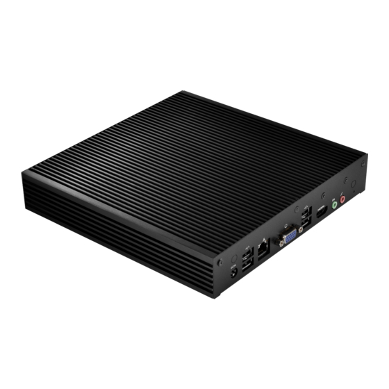
Page 7: Chapter 2 Product Overview
Chapter 2 Product Overview This chapter provides diagrams showing the location of important components of the iBOX-280. 2.1 Inside View Rear Panel HDD mounting bracket SO-DIMM sockets CPU Heatsink Front Panel... -
Page 8: Front View
2.2 Front View Description 2 x USB 2.0 Ports 2 x COM Ports Power LED HDD LED On-/off Switch Status LED Definitions Power LED Status Description Solid Green Power on Power off HDD Status LED Status Description HDD installed HDD uninstalled... -
Page 9: Rear View
iBox 2.3 Rear View No. Description No. Description Antenna Port Line out (Lime) LAN RJ-45 Port (LAN1)* HDMI Port (HDMI1) VGA Port (VGA1) 4 x USB 2.0 Ports Antenna Port DC Jack (DC_JACK1) Microphone (Pink) * There are two LEDs on each LAN port. Please refer to the table below for the LAN port LED indications. ACT/LINK LED SPEED LED LAN Port... -
Page 10: Chapter 3 Hardware Installation
Chapter 3 Hardware Installation This chapter provides step-by-step procedures on how to install components. Installation Procedures Removing the chassis top cover Installing the memory modules (SO-DIMM) Installing the 2.5-inch hard drive Replacing the chassis top cover After making sure that you have properly connected the power supply and all the necessary peripherals, power on the system. -
Page 11: Removing The Chassis Top Cover
iBox 3.1 Removing the Chassis Top Cover 1. Remove the three screws on the front panel. 2. Remove the three screws on the rear panel. 3. Remove the four screws in the bottom case. 4. Lift up and remove the top cover. -
Page 12: Installing Memory Modules (So-Dimm)
3.2 Installing Memory Modules (SO-DIMM) This motherboard provides two 204-pin DDR3 (Double Data Rate 3) SO-DIMM slots. Please install the SO-DIMM module into the DDR3_A2 for the first priority. It is not allowed to install a DDR or DDR2 memory module into a DDR3 slot; otherwise, this motherboard and SO-DIMM may be damaged. -
Page 13: Installing The Hard Drive
iBox 3.3 Installing the Hard Drive Removing HDD Mounting Bracket 1. Remove the four screws that secure the HDD mounting bracket to the chassis. 2. Lift up and remove the HDD mounting bracket. - Page 14 Installing a 2.5-inch Hard Drive 1. Place the HDD into the HDD mounting bracket with the printed circuit board side facing down. Carefully align the mounting holes in the hard drive and the HDD carrier. 2. Secure the hard drive into the place using the four screws. 3.
-
Page 15: Replacing The Top Cover
iBox 3.4 Replacing the Top Cover 1. Replace the top cover, making sure the mark on the top cover is aligned with the HDD mounting bracket. 2. Secure the three screws on the front panel. 3. Secure the three screws on the rear panel. 4. - Page 17 3.5 Using the Wall Mount Bracket 1. Attach the Wall Mount Bracket to the base of iBOX-280 using the four screws (M3x4) 2. Mount the iBOX-280 to the wall using the four screws (M3x4).
-
Page 18: Chapter 4 Motherboard
Chapter 4 Motherboard 4.1 Motherboard Layout SATA_PWR1 DC_JACK1 INT_DC1 BLT_PWM1 USB 2.0 UPS_IN1 T: USB0 B: USB1 DC_CTL1 AMP_CTL1 LAN1 SATAII_1 BAT1 SATAII_2 MSATA_SEL1 BIOS Chip USB 2.0 T: USB2 JGPIO1 B: USB3 CPU_FAN1 CLRCMOS1 PWR_JP1 HDMI1 PANEL1 DN2800MT Line Out CHA_FAN1 USB6_7 USB4_5... - Page 19 iBox No. Description 2-pin ATX Power Input/Output Connector 2-pin UPS Module Power Input Connector DC_CTL1 SATA Power Output Connector AMP_CTL1 BLT_PWM1 LVDS Panel Connector BLT_CTL1 PNL_PWR1 10 BKT_PWR1 11 Digital Input / Output Power Select 12 Digital Input / Output Pin Header 13 4-Pin CPU FAN Connector 14 ATX/AT mode Selection 15 System Panel Header...
-
Page 20: Motherboard Specifications
4.2 Motherboard Specifications Form Factor Dimensions Mini-ITX (6.7-in x 6.7-in) ® - Intel Dual-Core Atom CedarView Processor N2800 - Supports Hyper-Threading Technology Core Number Processor Max Speed N2800: 1.86 GHz System L3 Cache Chipset NM10 BIOS UEFI Mini-PCIe 1 (Half Size) + 1 (Full Size, shared with m-SATA) Expansion mSATA 1 (share with mini-PCIe) - Page 21 AT/ATX Supported Requirements Power On -AT : Directly PWR on as power input ready -ATX : Press button to PWR on after power input ready Environment Temperature 0ºC – 60ºC * For detailed product information, please visit our website: http://www.asrock.com...
-
Page 22: Jumpers Setup
4.3 Jumpers Setup The illustration shows how jumpers are setup. When the jumper cap is placed on the pins, the jumper is “Short”. If no jumper cap is placed on the pins, the jumper is “Open”. The illustration shows a 3-pin jumper whose pin1 and pin2 are “Short” when a jumper cap is placed on these 2 pins. - Page 23 iBox BLT_CTL1 Signal Name (8-pin BLT_CLT1) CON_LBKLT_EN (see p.13, No. 8) CON_LBKLT_CTL LCD_BLT_VCC LCD_BLT_VCC GPIO_BLT_UP GPIO_BLT_DW DC_CLT1 Power Input Voltage > (2-pin DC_CTL1) +12V: Short (see p.13, No. 3) Power Input Voltage ≤ +12V: Open Signal Name Panel Power Selection +3.3V (4-pin PNL_PWR1) (see p.13, No.
- Page 24 ATX/AT Mode 1-2 : AT Mode Selection 2-3 : ATX Mode 3 2 1 (3-pin PWR_JP1) (see p.13, No. 14) MSATA_SEL1 1-2 : mPCIE (Disable SATAII_2) 2-3 : mSATA (3-pin MSATA_ SEL1) (see p.13, No. 31)
-
Page 25: Onboard Headers And Connectors
iBox 4.4 Onboard Headers and Connectors Onboard headers and connectors are NOT jumpers. Do NOT place jumper caps over these headers and connectors. Placing jumper caps over the headers and connectors will cause permanent damage to the motherboard. LVDS Panel Signal Name Signal Name Connector... - Page 26 Signal Name PIN Signal Name Digital Input / JGPIO_PQR1 Output Pin Header (10-pin JGPIO1)(see SIO_GP3 SIO_GP7 p.13, No. 12) SIO_GP2 SIO_GP6 SIO_GP1 SIO_GP5 SIO_GP0 SIO_GP4 UPS Module Power Input Connector (2-pin DC_UPS1) (see p.13, No. 2) ATX Power Input/ Output Connector (2-pin INT_DC1) (see p.13, No.
- Page 27 iBox Though this motherboard provides 4-Pin CPU fan (Quiet Fan) support, the 3-Pin CPU fan still can work successfully even without the fan speed control function. If you plan to connect the 3-Pin CPU fan to the CPU fan connector on this motherboard, please connect it to Pin 1-3.
- Page 28 PWRBTN (Power Switch): Connect to the power switch on the chassis front panel. You may configure the way to turn off your system using the power switch. RESET (Reset Switch): Connect to the reset switch on the chassis front panel. Press the reset switch to restart the computer if the computer freezes and fails to perform a normal restart.
- Page 29 iBox Chassis Intrusion Headers This motherboard supports (2-pin CI1/CI2: see p.13, CASE OPEN detection feature No. 29) that detects if the chassis cover Signal has been removed. This feature requires a chassis with chassis intrusion detection design. Front Panel Audio Header This is an interface for front PRESENCE# (9-pin HD_AUDIO1)
- Page 30 AFD# Print Port Header This is an interface for print port ERROR# PINIT# (25-pin LPT1) SLIN# cable that allows convenient (see p.13, No. 22) connection of printer SPD7 devices. SPD6 ACK# SPD5 BUSY SPD4 SPD3 SLCT SPD2 SPD1 SPD0 STB# DMIC1 Signal Name (4-pin DMIC1)
-
Page 31: Expansion Slots
iBox 4.5 Expansion Slots (PCI Express, mini-PCIe and mini-PCIe/ mini-SATA Slots) There is 1 PCI Express slot, 1 mini-PCIe slot and 1 mini-PCIe/mini-SATA slot on this motherboard. Before installing an expansion card, please make sure that the power supply is switched off or the power cord is unplugged.