Table of Contents
Advertisement
Quick Links
Advertisement
Table of Contents

Related Manuals for ASROCK iBOX-420-DL


Summary of Contents for ASROCK iBOX-420-DL
- Page 1 User Manual Version 1.0 Published February 2019...
- Page 2 Important Safety Instructions Pay close attention to the following safety instructions before performing any of the operation. Basic safety precautions should be followed to protect yourself from harm and the product from damage: • Operation of the product should be carried out by suitably trained, qualified, and certified personnel only to avoid risk of injury from electrical shock or energy hazard.
-
Page 3: Table Of Contents
How to Install the 2.5-inch Hard Drive How to Install the Memory Modules (DDR3 Low Voltage (1.35V)) How to Install the VESA Bracket Positions of the iBOX-420-DL Chapter 4 Software and Utilities Operation Installing Drivers Chapter 5 UEFI SETUP UTILITY Introduction 5.1.1... - Page 4 Advanced Screen 5.3.1 CPU Configuration 5.3.2 Chipset Configuration 5.3.3 Storage Configuration 5.3.4 Super IO Configuration 5.3.5 ACPI Configuration 5.3.6 Trusted Computing Hardware Health Event Monitoring Screen Security Screen Boot Screen Exit Screen...
-
Page 5: Chapter 1 Introduction
Because the hardware specifications might be updated, the content of this documentation will be subject to change without notice. 1.1 Package Contents • iBOX-420-DL Barebone System with: iBOX-420-DL Chassis Motherboard (pre-installed) *The barebone system does not include memory, hard drive and mSATA SSD. -
Page 6: Product Specifications
1.2 Product Specifications iBOX-420-DL Barebone Intel® Apollo Lake N4200/N3350 Processor Chipset Intel® N4200/N3350 SoC Memory Supports DDR3L, 2 x SO-DIMM slots, Max. 8GB eMMC mSATA Optional slot 2.5”HDD Supports 1 x 2.5" SATA HDD* Gigabit LAN WiFi Optional Front I/O 1 x USB 3.0, 1 x Audio-out with MIC-In... - Page 7 Volume 0.6L (Liters) Operating 0°C~50°C Temperature * For iBOX-420-DL, it is not recommended to install 2.5” HDD. If you install the 2.5” HDD, please keep the iBOX- 420-DL in a vertical position to ensure better cooling performance.
-
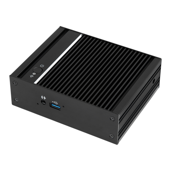
Page 8: Chapter 2 Product Overview
Chapter 2 Product Overview This chapter provides diagrams showing the location of important components of the iBOX-420-DL. 2.1 Front View Description Headphone & Microphone USB 3.0 (Type A) -
Page 9: Rear View
2.2 Rear View Description Kensington Lock Slot DC-In *DisplayPort HDMI USB 3.0 (Type A) RJ-45 *To use DisplayPort as a display output, please connect your monitor/display to HDMI Port when installing OS system. This DisplayPort only supports DP to D-Sub dongle and does not support DP to HDMI dongle and DP to DVI dongle. -
Page 10: Inside View
2.3 Inside View Description WiFi Module Slot mSATA Slot SO-DIMM Slots SATA 3.0 Connector Clear CMOS Pad *Clear CMOS Pad allows you to clear the data in CMOS. To clear CMOS, disconnect the power supply and short the Clear CMOS Pad. Hard disk drive tray (compatible with 2.5"... -
Page 11: Chapter 3 Hardware Installation
Chapter 3 Hardware Installation This chapter helps you install or remove important components. 3.1 How to Remove the Bottom Case 1. Remove the four screws on the bottom case. 2. Then lift up and remove the bottom panel.. -
Page 12: How To Install The Wifi Module (Optional)
3.2 How to Install the WiFi Module (Optional) 1. Locate the WiFi Module slot on the motherboard. 2. Carefully insert the WiFi Module into the slot. 3. Tighten the screw to secure the WiFi Module to the motherboard. -
Page 13: How To Install The Msata Ssd
3.3 How to Install the mSATA SSD 1. Locate the mSATA slot on the motherboard. 2. Carefully insert the mSATA SSD into the slot. 3. Tighten the screw to secure the mSATA SSD to the motherboard. -
Page 14: How To Install The 2.5-Inch Hard Drive
3.4 How to Install the 2.5-inch Hard Drive 1. Remove the four screws on the bottom case. Then lift up and remove the bottom panel. 2. Attach the HDD cage to the bottom panel and secure it using the four screws. Then connect the SATA cable to the HDD. - Page 15 3. Connect the SATA Data and Power Cable to the motherboard. 4. Then reinstall the bottom panel.
-
Page 16: How To Install The Memory Modules (Ddr3 Low Voltage (1.35V))
3.5 How to Install the Memory Modules (DDR3 Low Voltage (1.35V)) 1. The iBOX-420-DL requires DDR3L SO-DIMM (1.35V). 2. For dual channel configuration, you always need to install identical (the same brand, speed, size and chip-type) DDR3L SO-DIMM pairs. The SO-DIMM only fits in one correct orientation. It will cause permanent damage to the motherboard and the DIMM if you force the DIMM into the slot at incorrect orientation. -
Page 17: How To Install The Vesa Bracket
3.6 How to Install the VESA Bracket 1. Attach the two screws to the base of the iBOX-420-DL. 2. 2. Attach the VESA Bracket to the rear of a compatible display using the four screws. *Choose mounting holes depending on the mounting hole pattern of your LCD screen (75 mm ×... -
Page 18: Positions Of The Ibox-420-Dl
3.7 Positions of the iBOX-420-DL The iBOX-420-DL can be placed in vertical or horizontal position. DC-IN Jack on Top Horizontal Position Wall-mounted... -
Page 19: Chapter 4 Software And Utilities Operation
Chapter 4 Software and Utilities Operation 4.1 Installing Drivers The Support CD that comes with the motherboard contains necessary drivers and useful utilities that enhance the motherboard’s features. Running The Support CD To begin using the support CD, insert the CD into your CD-ROM drive. The CD automatically displays the Main Menu if “AUTORUN”... -
Page 20: Chapter 5 Uefi Setup Utility
Chapter 5 UEFI SETUP UTILITY 5.1 Introduction This section explains how to use the UEFI SETUP UTILITY to configure your system. You may run the UEFI SETUP UTILITY by pressing <F2> or <Del> right after you power on the computer, otherwise, the Power-On-Self-Test (POST) will continue with its test routines. -
Page 21: Navigation Keys
5.1.2 Navigation Keys Use < Use < Use < > key or < > key or < > key or < > key to choose among the selections on the menu bar, and > key to choose among the selections on the menu bar, and >... -
Page 22: Main Screen
5.2 Main Screen When you enter the UEFI SETUP UTILITY, the Main screen will appear and display the system overview. -
Page 23: Advanced Screen
5.3 Advanced Screen In this section, you may set the configurations for the following items: CPU Configuration, Chipset Configuration, Storage Configuration, Super IO Configuration, ACPI Configuration and Trusted Computing. Setting wrong values in this section may cause the system to malfunction. -
Page 24: Cpu Configuration
5.3.1 CPU Configuration Intel SpeedStep Technology Intel SpeedStep technology is Intel’s new power saving technology. Processors can switch between multiple frequencies and voltage points to enable power saving. The default value is [Enabled]. Configuration options: [Enabled] and [Disabled]. If you install Windows® OS and want to enable this function, please set this item to [Enabled]. - Page 25 Vanderpool Technology. This option will be hidden if the installed CPU does not support Intel Virtualization Technology. VT-d Intel® Virtualization Technology for Directed I/O helps your virtual machine monitor better utilize hardware by improving application compatibility and reliability, and providing additional levels of manageability, security, isolation, and I/O performance.
-
Page 26: Chipset Configuration
5.3.2 Chipset Configuration DRAM Frequency If [Auto] is selected, the motherboard will detect the memory module(s) inserted and as- sign the appropriate frequency automatically. Share Memory Configure the size of memory that is allocated to the integrated graphics processor when the system boots up. Onboard HD Audio Enable/disable onboard HD audio. - Page 27 Deep S5 Mobile platforms support Deep S5 in DC only and desktop platforms support Deep S5 in AC only. The default value is [Disabled]. Restore on AC/Power Loss Select the power state after a power failure. If [Power Off] is selected, the power will remain off when the power recovers.
-
Page 28: Storage Configuration
5.3.3 Storage Configuration SATA Controller(s) Use this item to enable or disable the SATA Controller feature. SATA Mode Selection Use this to select SATA mode. The default value is [AHCI Mode]. AHCI (Advanced Host Controller Interface) supports NCQ and other new features that will improve SATA disk performance but IDE mode does not have these advantages. -
Page 29: Super Io Configuration
5.3.4 Super IO Configuration COM1 Configuration Use this to set parameters of COM1. Select COM1 port type: [RS232], [RS422] or [RS485]. WDT Timeout Reset This allows users to enable/disable the Watch Dog Timer timeout to reset system. The default value is [Disabled]. -
Page 30: Acpi Configuration
5.3.5 ACPI Configuration Suspend to RAM Use this item to select whether to auto-detect or disable the Suspend-to-RAM feature. Select [Auto] will enable this feature if the OS supports it. ACPI HPET Table Use this item to enable or disable ACPI HPET Table. The default value is [Enabled]. Please set this option to [Enabled] if you plan to use this motherboard to submit Windows®... -
Page 31: Trusted Computing
5.3.6 Trusted Computing Security Device Support Enable or disable BIOS support for security device. -
Page 32: Hardware Health Event Monitoring Screen
5.4 Hardware Health Event Monitoring Screen In this section, it allows you to monitor the status of the hardware on your system, including the parameters of the CPU temperature, motherboard temperature, CPU fan speed, chassis fan speed, and the critical voltage. CPU Fan 1 Setting Select a fan mode for CPU Fan 1, or choose Customize to set 5 CPU temperatures and assign a respective fan speed for each temperature. -
Page 33: Security Screen
5.5 Security Screen In this section you may set or change the supervisor/user password for the system. You may also clear the user password. Supervisor Password Set or change the password for the administrator account. Only the administrator has authority to change the settings in the UEFI Setup Utility. Leave it blank and press enter to remove the password. -
Page 34: Boot Screen
5.6 Boot Screen This section displays the available devices on your system for you to configure the boot settings and the boot priority. Boot From Onboard LAN Use this item to enable or disable the Boot From Onboard LAN feature. Setup Prompt Timeout This shows the number of seconds to wait for setup activation key. - Page 35 CSM (Compatibility Support Module) Enable to launch the Compatibility Support Module. Please do not disable unless you’re running a WHCK test. If you are using Windows 8.1 64-bit and all of your devices support UEFI, you may also disable CSM for faster boot speed.
-
Page 36: Exit Screen
5.7 Exit Screen Save Changes and Exit When you select this option the following message, “Save configuration changes and exit setup?” will pop out. Select [OK] to save changes and exit the UEFI SETUP UTILITY. Discard Changes and Exit When you select this option the following message, “Discard changes and exit setup?”...