Summary of Contents for Siemens Rider 11, Rider 13 H,Rider 11 Bio
- Page 1 ___________________ Interface modules IM 153-4 PN and IM Introduction 153-2 HF ___________________ Product information SIMATIC ET 200M Interface modules IM 153-4 PN and IM 153-2 HF Product Information 12/2013 A5E02714952-04...
- Page 2 Legal information Warning notice system This manual contains notices you have to observe in order to ensure your personal safety, as well as to prevent damage to property. The notices referring to your personal safety are highlighted in the manual by a safety alert symbol, notices referring only to property damage have no safety alert symbol.
- Page 3 Table of contents Introduction ............................. 5 Product information ..........................7 Supplement to the sections ......................7 The new functions for the IM 153-4 ..................... 10 Interface modules IM 153-4 PN and IM 153-2 HF Product Information, 12/2013, A5E02714952-04...
- Page 4 Table of contents Interface modules IM 153-4 PN and IM 153-2 HF Product Information, 12/2013, A5E02714952-04...
-
Page 5: Introduction
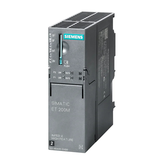
Introduction Overview This product information applies to: ● IM 153-4 PN interface module – 6ES7153-4AA01-0XB0, as of firmware version 4.x – 6ES7153-4BA00-0XB0, as of firmware version 4.x ● IM 153-2 HF interface module – 6ES7153-2BA02-0XB0 – 6ES7153-2BA82-0XB0 Supplement to the ET 200M operating instructions This product information is a supplement to the ET 200M (http://support.automation.siemens.com/WW/view/en/1142798) operating instructions. - Page 6 Introduction Configuration with STEP 7 or GSD You can configure the ET 200M using the above-named 6ES7153-4AA01-0XB0/6ES7153- 4BA00-0XB0 under STEP 7 V5.5 (with HSP 214 or HSP 213) or a GSD file. You can find the GSD file at Internet (http://support.automation.siemens.com/WW/view/en/25057900).
-
Page 7: Product Information
Product information Supplement to the sections Supplement to the ET 200M operating instructions This section lists all of the supplements to the sections of the ET 200M operating instructions. Supplement to section 3.5.4: Arrangement of the modules for the function "Change During Operation" and/or "Redundancy"... - Page 8 Product information 2.1 Supplement to the sections Supplement to section 7.10.4: Update of the IM 153-2Bxx1 Configuration as IM 153-2Bxx1 The firmware update is created separately with each IM 153-2. The IM 153-2 is integrated in the PCS 7 project. Procedure 1.
- Page 9 Product information 2.1 Supplement to the sections Supplement to section 9.1.3.1: Structure of the slave diagnostics If you have not performed the configuration with GSD, there are no module status and channel-related diagnostics blocks for the IM 153-1AA03. Figure 2-1 Structuring of the slave diagnostics new Interface modules IM 153-4 PN and IM 153-2 HF Product Information, 12/2013, A5E02714952-04...
-
Page 10: The New Functions For The Im 153-4
Product information 2.2 The new functions for the IM 153-4 Error in section 10.1 Pollutant concentration This sentence is correct: The ET 200M distributed I/O system satisfies the requirements of the standard ISA-71.04 serverity level G1;G2;G3. The new functions for the IM 153-4 Media redundancy Function for ensuring the network and system availability. - Page 11 Product information 2.2 The new functions for the IM 153-4 Configuration as Shared Device "IM153-4 PN ST as of V3.0 Shared Device" or "IM153-4 PN HF as of V3.0 Shared Device" must be used for the configuration of shared device. The remaining configuration is done in the usual way.
- Page 12 Product information 2.2 The new functions for the IM 153-4 SM 322 DO 16 x DC 24V/0,5 A, 6ES7322-8BH10-0AA0 You can also use the SM 322 DO 16 x DC 24V/0,5 A 6ES7322-8BH10-0AA0 module with the 6ES7153-4BA00-0XB0. Connection to H-CPU (6ES7153-4BA00-0XB0 only) In the case of system redundancy, you can connect the 6ES7153-4BA00-0XB0 to the following S7-400 CPUs: Order no.
- Page 13 Product information 2.2 The new functions for the IM 153-4 Principle for fastening PROFINET cable with cable ties The following describes how to fasten PROFINET cables with cable holders. The cable holders are available as accessories. 1. Screw the cable holder onto the interface module. 2.
- Page 14 Product information 2.2 The new functions for the IM 153-4 3. Connect the PROFINET cable to the cable holder using the cable tie. Interface modules IM 153-4 PN and IM 153-2 HF Product Information, 12/2013, A5E02714952-04...


