Table of Contents
Advertisement
Advertisement
Table of Contents

Related Manuals for Sunbeam in-ground fencing system


Summary of Contents for Sunbeam in-ground fencing system
- Page 1 essential in-ground fencing system STaTIC INSTRUCTION MaNUal...
-
Page 2: Table Of Contents
table of contents IMPoRtant safeGUaRDs . . . . . . . . . . . . . . . . . . . . . . . . . . . . . . . . . . . . . . . . . . . . . . . . . . . . . . . . . . . . . . . . . . . . . . . . . 3 KeyWoRD DefInItIons . -
Page 3: Important Safeguards
• This product is not intended to contain or provide protection against aggressive dogs. • Your dog should be in good health when using this product. • This product is not to be used on dogs less than 9 lbs. • This product is not to be used on dogs less than 6 months old. • Always remove the Receiver Collar prior to washing or grooming your dog. • A void leaving the Receiver Collar on the dog for more than 8 continuous hours per day. Prolonged collar use can cause pressure sores which may lead to skin irritation such as contact dermatitis or decubitus ulcers. If a rash is discovered discontinue use until the skin area heals completely. If condition persists for more than 48 hours, contact your veterinarian. • D o not attach a leash to the Sunbeam® Receiver Collar. A separate, non-metallic collar or harness may be used provided it does not interfere with the Sunbeam® Receiver Collar. • W arning: The Receiver Collar uses two Lithium (CR 2032) coin type batteries. Keep the batteries out of reach of children. If swallowed, immediately seek medical help as serious injury may occur. • T he Lithium coin battery(s) used in this product contains perchlorate material. Special handling may apply in California. Go to: www.dtsc.ca.gov/hazardouswaste/perchlorate for more information. • I MPORTANT: Each dog will have its own tolerance level, behavioral characteristics and individual environments; therefore, there is no way of knowing whether or how your dog will react to this product. If your dog has an aggressive temperament or has ever exhibited aggressive behavior, do not use this product until you have contacted a certified dog behaviorist. -
Page 4: Keyword Definitions
KeyWoRD DefInItIons • Base Transmitter: Sends the radio signal through the Boundary Wire . • B oundary Flags: A visual aid for the dog. The Boundary Flags will remind the dog where the Boundary Zone is located . • B oundary Zone: The Boundary Zone is the area beyond the Boundary Flags where the dog will receive a Static Correction. The dog will hear a Warning Tone as it approaches the Boundary Zone and will receive a Static Correction if they do not return to the Safe Zone immediately. • Boundary Wire: The wire that gives off a radio signal when the Base Transmitter is powered on . • E xclusion Zones: Areas in your layout such as gardens, pools or other lawn decorations, that you want to protect. You can exclude these areas from your layout while still giving your dog access to your yard. -
Page 5: Product Overview
Do not Use tHIs fencInG systeM UntIl yoU Have ReaD tHese InstRUctIons PRoDUct oveRvIeW ADJUSTABLE BUCKLE FABRIC COLLAR MAIN CONTROL BUTTON: • On/Off • Correction QUICK RELEASE level adjustment CLASP • LED STAINLESS STEEL PROBES: Correction administering system BATTERY DOOR: Located on bottom of unit for battery installation and removal... - Page 6 POWER INDICATOR: YARD SWITCH: (only the middle LED with light up) • HI setting recommended for large yards • Solid green LED: Base Transmitter ON • LO setting recommended for small yards • Flashing green LED: Connection problem MOUNTING HOLE MOUNTING HOLE SPRING-LOADED...
-
Page 7: How It Works
HoW It WoRKs The Sunbeam® Essential In-Ground Fencing System is a training aid that helps train your dog to stay within a defined boundary. The System uses a wire to create a Boundary Zone where your dog will receive a Warning Tone and a Static Correction. Flags are arranged along the Boundary Zone to give your dog a visual aid. The area encompassed by the Boundary Flags is the Safe Zone. The Safe Zone is the area where your dog can roam without receiving a Warning Tone or Static Correction from the Receiver Collar. The Boundary Flags can be removed at the end of the training process. The Sunbeam® Essential In-Ground Fencing System uses the buried wire to broadcast a radio signal. The buried wire acts as an antenna converting the signal into electromagnetic waves. The Base Transmitter controls the range of the signal around the wire. Inside the Sunbeam® Essential Receiver Collar is a small radio receiver. When the dog moves close to the Boundary Zone, the Receiver Collar will release a Warning Tone so your dog knows it is nearing the Boundary Zone. If your dog moves into the Boundary Zone, it will receive a Static Correction. To achieve the best results with the Sunbeam® Essential In-Ground Fencing System, it is important that you complete the training that follows in the included training manual. If you have multiple dogs additional collars can be added to your system. Contact the retailer from which you purchased the In-Ground Fencing System or call 866-537-2249. oPeRatInG InstRUctIons WARNING: To avoid injury make sure there are no buried electrical cables in the surrounding area where you will lay your Boundary Wire. Electric power lines, natural gas pipelines, communications lines and other utility services, if damaged, can create a hazard that could endanger you and your property. - Page 8 • The Boundary Wire should turn corners gradually. Avoid sharp turns as this may cancel out the signal. • I f you have more than 1/3 acre of property you will need wire chart additional Boundary Wire to expand your main loop . The wire chart will help you determine how many 500 ft. Boundary Wire Acres Wire Needed # of Spools spools you will need. The chart is based on a single loop layout. There is one 500 ft. Boundary Wire spool included in your kit. ¼ 415 ft. 1 (included) ¹/ 480 ft. 1 (included) • W hen you have decided on the amount of wire you will need for ½...
- Page 9 double Loop Layout This layout allows your dog access to a portion of the yard that you choose. You should lay the two parallel Boundary Wires at least 4 to 5 feet apart to avoid interference and canceling the signal. double Loop Single Side Boundary double Loop Layout IMPORTANT: This layout is not recommended unless the property is fenced on the rest of the sides as shown in the diagram. This layout allows you to create a single sided barrier. You should run Boundary Wire from the Base Transmitter to the area where you want to create the boundary. Create a long loop of Boundary Wire where you want to create the barrier. Make sure the loop is long enough so that the dog cannot go around it. Make sure that there is at least 4 to 5 feet between the parallel Boundary Wires to avoid interference and canceling the signal. Use Twisted Wire in the area that leads back to the Base...
-
Page 10: Setting Up The Base Transmitter
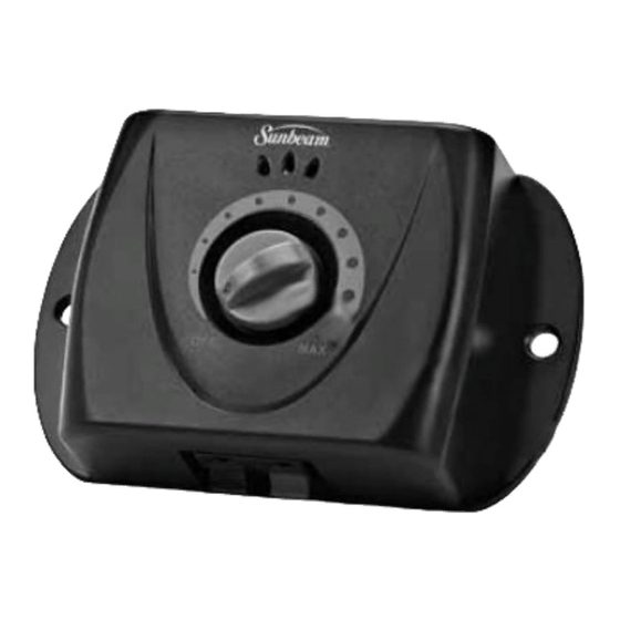
settInG UP tHe base tRansMItteR IMPORTANT: The Base Transmitter should be placed in a dry, well ventilated area indoors. Do not place the Base Transmitter in an area where temperatures fall below freezing (fig. 1). Do not place the Base Transmitter within 3 feet of any appliances or large metal objects (fig. 2). AC adaptor is for indoor use only. figure 1 figure 2 The Base Transmitter creates the signal that goes to the Boundary Wire to create the Boundary Zone. From the Base Transmitter you control the Boundary Zone Area (the distance from the wire where the warning signal and correction begins). The Boundary Wire must run from the Base Transmitter to outside. It is recommended you mount the Base Transmitter to the inside of an exterior wall so you can easily run the Boundary Wire outside. Remember, the Boundary Wire must begin at the Base Transmitter and make a continuous loop back to the Base Transmitter . On the back of the Base Transmitter there is a Yard Switch (fig. 3). The default setting is Hi. Use this setting to test the system before you mount the Base Transmitter to the wall. If the Boundary Zone is too big, adjust the Yard Switch to Low . figure 3... -
Page 11: Testing The System
testInG tHe systeM After you have sketched out your layout test the system prior to burying the Boundary Wire. Lay your Boundary Wire following your planned design. Be careful when you lay out the Boundary Wire as any damage will affect the signal strength of the In Ground Fence. • L ay out the Boundary Wire above ground following your planned design. Add about 20% extra Boundary Wire to allow for burying. • U se the supplied Boundary Wire for the areas you do not want your dog to pass. • U se twisted pair wire in the areas where you want to cancel out the signal and allow your dog to safely walk through. Read more about How to Twist Wire on page 12 . • O nce all of the wires are laid out splice the pieces together, if necessary, to create a continuous wire. Read more about How to Splice Wire on page 13. figure 4 • U sing a wire stripper, strip about one half inch (½”) of the coating from the tips of the Boundary Wire to expose clean, non-corroded Boundary Wire. (fig. 4) • IMPORTANT: Do not insert the Boundary Wires into the Base Transmitter while it is plugged in. -
Page 12: How To Twist Wire
HoW to tWIst WIRe Twisting two Boundary Wires together causes the radio signal to cancel out . The Boundary Wire should be twisted 10 to 12 times per foot to cancel the signal. In the areas where you install Twisted Wire you will create a Safe Spot where the dog can walk without being corrected by the Receiver Collar. For example, the wire that connects the Base Transmitter to your outer Boundary Wire should be Twisted Wire and should not warn or correct your dog . Mark on your plan layout where your Twisted Wire is located for future reference. Twisted Wire cannot be part of your main loop. The main purpose for Twisted Wire is to join the main loop to the Base Transmitter (fig. 8). You can also use Twisted Wire to connect the Exclusion Zones to the main Boundary Wire (fig 9). -
Page 13: How To Splice Wire
HoW to sPlIce WIRe If you are using Twisted Wire or additional Boundary Wire to expand your main loop, you will need to splice the wires together . Mark on your plan layout where your wire splices are located for future reference. Your system should not be energized when splicing the wires. • U sing a wire stripper, strip about one half inch of the coating from the tips of the Boundary Wire to expose clean, non-corroded Boundary Wire. • H old the wires together. Insert the wires into the supplied wire nut ensuring that there is no copper exposed beyond the end of the wire nut. Twist the wires together in a clockwise direction . Pull lightly on the wire nut to make sure it is secure . • Tie a knot 4 inches from the wire nut. -
Page 14: Installing The Boundary Wire
InstallInG tHe boUnDaRy WIRe The Boundary Wire is buried to protect it from being damaged. If the Boundary Wire is damaged you risk having gaps where there could be poor signal strength in your In Ground Fence. • U sing a shovel, dig a narrow trench along your planned Boundary Zone where you will lay your Boundary Wire. The trench should be about 3 to 6 inches deep. Use a blunt tool such as a wooden paint stick to push the boundary wire into the trench. Be careful not to damage the boundary wire insulation. • P lace the Boundary Wire into the trench and bury the wire. It is recommended that you lay your Boundary Wire in one yard sections . Make sure you allow some slack when laying the Boundary Wire to allow for expansion and contraction with temperature variations. • C over the area where you buried the wire and tap on the surface lightly to secure . -
Page 15: Connecting & Testing The System
connectInG & testInG tHe systeM • U se a ruler to measure the distance between the mounting holes on the sides of your Base Transmitter. The Base Transmitter must mount to a stationary surface. • U sing the mounting holes on your Base Transmitter as a mounting template, use a level and a ruler to mark on your wall where the screws will go . • U sing a Philips head screwdriver mount the Base Transmitter directly into the wall. If you are not mounting directly into the wall stud, install the screw anchors supplied before attaching the transmitter to the wall. figure 18 • T he Boundary Wire must run to the outside where you will lay out your system. Make sure that the Boundary Wire is not being pinched by any doors or windows as this will damage the wire. If necessary, you may have to drill a hole through the wall . -
Page 16: Setting The Boundary Width
settInG tHe boUnDaRy WIDtH The Boundary Zone is the area beyond the Boundary Flags where the dog will receive a Static Correction. The dog will hear a Warning Tone as it approaches the Boundary Zone and will receive a Static Correction if they do not return to the Safe Zone immediately. You should set the Boundary Zone width as wide as possible to give your pet the largest warning and correction zone without reducing the Safe Zone. Initially consider a Boundary Zone width of a minimum of 10 feet. As your dog becomes accustomed to the System you may be able to reduce your Boundary Zone width. You can adjust the Boundary Zone by turning the knob on the Base Transmitter. As you turn the knob to the right you are increasing the Boundary Zone width (how far from the wire the warning and correction begins). NOTE: Make sure you give the dog at least 3 feet of Safe Zone in all areas, paying special attention to narrow areas on the side of the home. • Begin with the Boundary Zone knob turned to MAX. • T urn your Receiver Collar on and place the Test Light indentation holes directly onto the Receiver Collar probes. • C hoose a section of straight Boundary Wire that is at least 50 feet long. • S lowly bring the Receiver Collar near the Boundary Wire at your pet’s neck level with probes facing up. As you approach the Boundary Zone you will hear a Warning Tone and the Test Light will flash. The Warning Tone indicates the beginning of the Boundary Zone. • M easure the distance from the spot where you heard the Warning Tone to the Boundary Wire. This distance is your Boundary Zone. Remember the area encompassed by the Boundary Flags is the Safe Zone. The Safe Zone is the area where the dog can roam without receiving a Warning Tone or Static Correction from the Receiver Collar. • Test in several different areas to make sure the system is functioning properly. • Y ou can decrease the area of the Boundary Zone width by turning the Boundary Zone knob to the left and testing using your Receiver Collar and Test Light . -
Page 17: Setting Up The Boundary Flags
settInG UP tHe boUnDaRy flaGs • Y ou must set up the Boundary Flags as a visual aid for your dog. The Boundary Flags will remind your dog where the Boundary Zone is located. • U sing the Receiver Collar and Test Light as a guide, begin placing your Boundary Flags at the point where you hear the Warning Tone . Space the Boundary Flags about one to two yards apart in small yards and about ten to fifteen feet apart in large yards. • I f there are areas of the Boundary Zone where you cannot plant the flags into the ground fill a small can with sand, place the filled can on the edge of the Boundary Zone and place the flag in the sand. Repeat this process until you have marked the entire Boundary Zone with Boundary Flags. ReceIveR collaR oPeRatInG InstRUctIons batteRy InstallatIon IMPORTANT: This step is to be completed when the collar is NOT on your dog. -
Page 18: Collar Fitting
Proper fit of the Sunbeam® Receiver Collar is essential to establish a good training foundation and optimal performance. NOTE: Batteries should be installed properly and the Receiver Collar should be in the OFF position before proceeding with fitting the collar to your dog . STEP 1: Ensure dog is in a relaxed position . STEP 2: With the collar clasp open loosen the adjustment buckle such that it can reach completely around your dog’s neck. (fig. 27) When buckled, the collar should rest directly behind the dog’s ears (the highest part of the neck). (fig. 28) Note: Make sure both stainless steel probes go through the coat completely and make contact with the skin . figure 27 Use the longer stainless steel probes if the coat does not allow the shorter probes to reach the skin . -
Page 19: Ready To Use
ReaDy to Use Note: The BATTERY INSTALLATION and COLLAR FITTING steps must be completed before you are ready to use. STEP 1: Holding the main body of the Sunbeam® Receiver Collar in both hands PRESS and HOLD the Control Button for 4 seconds. Note: You will hear one long beep followed by a sequence of short beeps and flashing green LED indicating which correction level is in use . The Receiver Collar will recall the last setting or the default setting (level 1 or low). STEP 2: Set correction level by pressing and holding (approximately 2 seconds) the Control Button . Once the collar is ON press the Control Button once to toggle to the next correction level . -
Page 20: Training Guide
It is important to read this section completely before beginning to train your dog to use the Sunbeam® Essential In-Ground Fencing System. The System is not a solid fence and will not contain your pet as well as a solid fence. do not allow your dog to run free until the training process is complete. Keep your dog on a leash, tied down, or confined to a separate area until training is complete. -
Page 21: Lesson #1 - Boundary Flag Awareness
RecoGnItIon level You will need to test your dog to see which correction level is appropriate for your dog’s temperament. Always begin training with the Receiver Collar on level 1. If your dog does not respond to the Static Correction on level 1 change the setting to level 2. If there is no response from your dog at level 2 change the setting to level 3. This process is explained further in Lesson #2 – Static Correction. NOTE: Once your dog begins training, they may be reluctant to leave the Safe Zone for car rides or walks. Always remove the Receiver Collar and replace it with a regular collar and leash before taking your dog out of the Safe Zone. You may need to carry your dog of out of the Safe Zone if it’s not possible to walk your dog out using praise and commands. In addition, if you are going to walk your dog out of the Safe Zone you should always do this in the same area of the boundary so they become more familiar with this process in the future. lesson #1 – boUnDaRy flaG aWaReness Lesson #1 is intended for days 1 and 2 of training and is designed to provide your dog with an awareness of the Boundary Zone area and helps them associate the Warning Tones with the Boundary Flags. During these days you should train for 10 to 15 minutes three times a day. The objective is to teach your dog to recognize the Boundary Flags and the Warning Tone . Your dog should be wearing a non-metallic collar (without tags) that they cannot slip out of. You will attach that collar to a leash. You will also need several small-sized treats. 1. T urn on the Receiver Collar and hold it in your hand. Hold the Receiver Collar by the fabric collar and do not touch the probes. Do not put the Receiver Collar on your dog. (fig. 32) 2. Walk your dog on the leash into the Safe Zone. 3. Hold the Receiver Collar at your dog’s neck level and continue walking your dog in the Safe Zone. 4 . Praise and reward your dog with a treat . 5. Hold the Receiver Collar at your dog’s neck level and begin walking your dog toward the Boundary Flags. -
Page 22: Lesson #2 - Static Correction
lesson #2 – statIc coRRectIon Lesson #2 is intended to last for up to a week and helps your dog learn to move away from the Boundary Zone on their own after receiving a correction. To achieve the best results, you should again train for 10 to 15 minutes a session three times a day. The objective is to introduce your dog to the Static Correction and teach them where the correction occurs. This will also teach your dog that there is a consequence for moving into the Boundary Zone. This step will also identify your dog’s level of recognition to the correction. This helps you to select the appropriate correction level on the collar that will be used for the rest of your lessons. Again for this lesson, your dog should be wearing a non-metallic collar (without tags) that they cannot slip out of. You will attach that collar to a leash. You will also need several small-sized treats. 1 . Turn on the Base Transmitter . 2 . Turn on the Receiver Collar and set the correction to level 1 . 3. P lace the Receiver Collar on your dog’s neck below the non-metallic collar. Make sure the non-metallic collar is not touching the probes on the Receiver Collar. -
Page 23: Lesson #3 - Adjusting To Distractions
lesson #3 – aDjUstInG to DIstRactIons Lesson #3 is intended to teach your dog to stay in the Safe Zone even when there are distractions outside of the Safe Zone. To achieve the best results, you should train for 10 to 15 minutes a session three times a day. This phase of the training may last several days or longer depending on how well your dog responds to distractions while in the Safe Zone. Your dog should again be wearing a non-metallic collar (without tags) that they cannot slip out of. You will attach that collar to a leash. You will also need several small-sized treats. For this lesson, you will need to make a list of every distraction that will tempt your dog to leave the play area. Some of the things that should be on your distraction list include favorite objects and toys, family members, friends, neighborhood dogs and cats, children on bicycles, squirrels, etc. Choose your dog’s favorite object from your distraction list and have it handy (such as a favorite toy or bone). 1 . Turn on the Base Transmitter . 2. Turn on the Receiver Collar and be sure that you are on the appropriate correction level for your dog. 3. P lace the Receiver Collar on your dog’s neck below the non-metallic collar. Make sure the non-metallic collar is not touching the probes on the Receiver Collar. 4. Walk your dog on the leash in the Safe Zone. 5 . Praise and reward your dog with a treat . 6 . -
Page 24: Lesson #4 - Taking Your Dog Off Leash
6. N ow, have the family member slowly walk away from the dog and past the Boundary Flags. The family member should not interact with the dog in any way. a. If your dog does not follow the family member, praise and reward the dog with a treat. b. I f your dog moves toward the family member, allow your dog to move toward the Boundary Zone. When your dog receives the Static Correction immediately move your dog away from the Boundary Flags and into the Safe Zone. Again, you may need to encourage your dog to come to you by calling them and putting gentle pressure on the leash. When you are about 10 feet away from the Boundary Flags stop to praise and reward your dog with a treat . 7. O nce the dog refuses to follow the family member across the Boundary Zone, repeat this process using another family member as the distraction. Each family member, friend, or neighbor should be treated as a separate distraction . 8. Continue training with each distraction separately until your dog is consistently staying in the Safe Zone. 9 . Turn off the Base Transmitter . Do not move on to Lesson #4 until your dog has learned to stay in the Safe Zone area when distracted. lesson #4 –... -
Page 25: Lesson #5 - Unsupervised Freedom
7 . Turn off the Base Transmitter . lesson #6 – ReMovInG tHe flaGs After one month of unsupervised freedom you can begin to remove the Boundary Flags. Start by removing every other Boundary Flag once a week until all of the Boundary Flags are removed. Your training is an ongoing process . As you remove the Boundary Flags continue to use distractions to make sure your dog understands that there is a Boundary Zone. Periodical reinforcement of your training will increase effectiveness of your Sunbeam® In-Ground Fencing System. After a period of time many dogs will back away from the Boundary Zone after hearing the Warning Tone alone. When you are ready you can replace the stainless steel probes with the plastic probes included in your kit. When using the plastic probes, your dog cannot receive a Static Correction but can still hear the Warning Tone. -
Page 26: Care And Maintenance
MaIntenance The Sunbeam® Receiver Collar is weatherproof but is NOT submersible so care must be taken when cleaning. • Always remove the battery before cleaning • Use a clean damp cloth, water only • Never use any household or industrial cleaners • Do not submerse the unit in water or any other liquid • K eep the dog’s coat and skin clean in the area where the collar makes contact • Check the fit of the collar several times per day • W ipe the stainless steel probes weekly with a damp cloth while collar is in OFF position Note: The Lithium coin batteries used in this product contain perchlorate material. Special handling may apply in California. Go to: www.dtsc.ca.gov/hazardouswaste/perchlorate for more information. fcc stateMent Potential for Radio/Television Interference This product has been tested and found to comply with the limits for a Class B digital device, pursuant to part 15 of the FCC rules. These limits are designed to provide reasonable protection against harmful interference in a residential installation. The product generated, uses, and can radiate radio frequency energy and, if not installed and used in accordance with the instructions, may cause harmful interference to radio communications. However, there is no guarantee that the interference will not occur in a particular installation. If the product does cause harmful interference to radio or television reception, which can be determined by turning the product on or off, the user is encouraged to try to correct the interference by one or more of the following measures: • Reorient or relocate the receiving antenna. • Increase the separation between the product and the receiver. • C onnect the product into an outlet on a circuit different from that to which the receiver is connected. • C onsult the dealer or an experienced radio/TV technician for help. -
Page 27: Year Warranty
JCS or an authorized Sunbeam® service center. Further, the warranty does not cover: Acts of God, such as fire, flood, hurricanes and tornadoes.