NETGEAR ProSafe GS728TP Hardware Installation Manual
Gigabit smart switches
Hide thumbs
Also See for ProSafe GS728TP:
- Hardware installation manual (36 pages) ,
- Installation manual (2 pages) ,
- Software administration manual (275 pages)

Related Manuals for NETGEAR ProSafe GS728TP


Summary of Contents for NETGEAR ProSafe GS728TP
- Page 1 ProSafe® GS752TP, GS728TP, and GS728TPP Gigabit Smart Switches Hardware Instal lation G u ide 350 East Plumeria Drive San Jose, CA 95134 December 2012 202-11136-01 v1.0...
-
Page 2: Technical Support
© NETGEAR, Inc. All rights reserved. Technical Support Thank you for choosing NETGEAR. To register your product, get the latest product updates, get support online, or for more information about the topics covered in this manual, visit the support website at http://support.netgear.com. -
Page 3: Table Of Contents
GS752TP Front Panel and Back Panel Configuration....10 GS728TP Front Panel and Back Panel Configuration....11 GS728TPP Front Panel and Back Panel Configuration . - Page 4 GS752TP, GS728TP, and GS728TPP Gigabit Smart Switch Appendix A Troubleshooting Troubleshooting Chart ........28 Additional Troubleshooting Suggestions .
-
Page 5: Chapter 1 Introduction
The GS752TP, GS728TP, and GS728TPP Gigabit Smart Switches Hardware Installation Guide describes how to install and power on the GS752TP, GS728TP, and GS728TPP Gigabit Smart Switch. The information in this manual is intended for readers with intermediate computer and Internet skills. -
Page 6: Overview
48 or 24 10/100/1000 Mbps AutoSensing Gigabit Ethernet switching ports. • GS752TP and GS728TP. The first 8 ports are PoE+ providing 30 W of DC power, and the remaining copper ports are PoE (Power over Environment) providing 15.4W of DC power. - Page 7 GS752TP, GS728TP, and GS728TPP Gigabit Smart Switch • IEEE 802.3z (1000BASE-x) • IEEE802.3af (DTE Power via MDI) • IEEE802.3at (DTE Power via MDI Enhancements) • IEEE802.3az (Energy Efficient Ethernet) • IEEE 802.3x (Full-duplex flow control) • AutoSensing and auto-negotiating capabilities for all ports.
-
Page 8: Package Contents
GS752TP, GS728TP, and GS728TPP Gigabit Smart Switch Package Contents Figure 1 shows the package contents of the GS752TP, GS728TP, and GS728TPP Gigabit Smart Switch. Rubber footpads AC power cord Rack-mount kit Resource CD Installation guide Figure 1. Package contents Verify that the package contains the following: •... -
Page 9: Chapter 2 Physical Description
Physical Description This chapter describes the GS752TP, GS728TP, and GS728TPP Gigabit Smart Switch hardware features. Topics include: • GS752TP Front Panel and Back Panel Configuration • GS728TP Front Panel and Back Panel Configuration • GS728TPP Front Panel and Back Panel Configuration •... -
Page 10: Gs752Tp Front Panel And Back Panel Configuration
GS752TP, GS728TP, and GS728TPP Gigabit Smart Switch GS752TP Front Panel and Back Panel Configuration The GS752TP Gigabit Smart Switch has 48 10/100/1000 Mbps copper ports and four dedicated 100/1000 Mbps SFP fiber ports. Each port is capable of sensing the line speed and negotiating the duplex mode with the link partner automatically. -
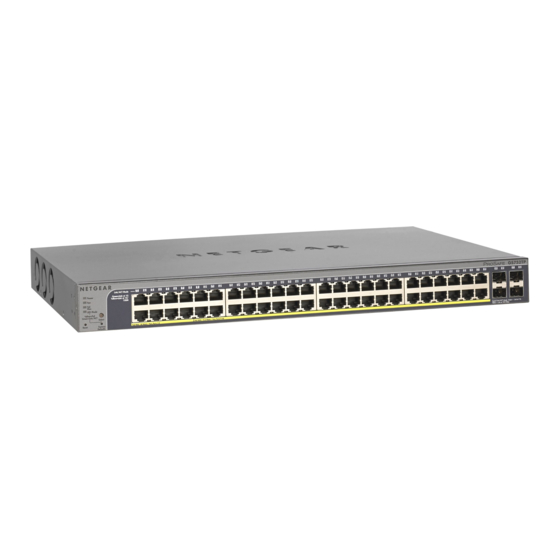
Page 11: Gs728Tp Front Panel And Back Panel Configuration
The back panel contains a power connector. GS728TP Front Panel and Back Panel Configuration The GS728TP Gigabit Smart Switch has 24 10/100/1000 Mbps copper ports and four dedicated 100/1000 Mbps SFP fiber ports. Each port is capable of sensing the line speed and negotiating the duplex mode with the link partner automatically. -
Page 12: Gs728Tpp Front Panel And Back Panel Configuration
Port Status and Port Speed LEDs. • Power, Fan Status, Max PoE, and LED Mode LEDs. Figure 5 illustrates the NETGEAR GS728TPP Gigabit Smart Switch back panel. Power connector Figure 5. Back panel The back panel contains a power connector. -
Page 13: Port Leds
• Port Status and Port Speed LEDs. • Power, Fan Status, Max PoE, and LED Mode LEDs. Figure 7 illustrates the NETGEAR GS728TPP Gigabit Smart Switch back panel. Power connector RPS connector Figure 7. Back panel The back panel contains: •... -
Page 14: Led Designations
GS752TP, GS728TP, and GS728TPP Gigabit Smart Switch LED Designations Port LEDs The following table describes the RJ-45 and dedicated SFP port LED designations. Designation Link/ACT LED mode for copper Link/ACT Mode LED: ports 1–48 or 1–24 • Off. No link is established. -
Page 15: System Leds
GS752TP, GS728TP, and GS728TPP Gigabit Smart Switch System LEDs The following table describes the system LED designations. Designation Power • Solid green. The device is powered on; runtime code is operating. • Blinking green. The internal power supply has failed and the system is drawing power from a remote power supply or PoE power from an external power supply. -
Page 16: Device Hardware Interfaces
GS752TP, GS728TP, and GS728TPP Gigabit Smart Switch Device Hardware Interfaces RJ-45 Ports RJ-45 ports are AutoSensing ports. When you insert a cable into an RJ-45 port, the switch automatically ascertains the maximum speed (10, 100, or 1000 Mbps) and duplex mode (half-duplex or full-duplex) of the attached device. -
Page 17: Reset Button
GS752TP, GS728TP, and GS728TPP Gigabit Smart Switch Reset Button The Smart Switch has a Reset button on the front panel to allow you to manually reboot the switch. This action is equivalent to powering the unit off and back on. The last saved configuration is loaded into the switch as it resets. -
Page 18: Chapter 3 Applications
10 Mbps, 100 Mbps, and 1000 Mbps hubs and switches. Desktop Switching The GS752TP, GS728TP, and GS728TPP Gigabit Smart Switch can be used as a desktop switch to build a small network that enables users to have 1000 Mbps access to a file server. -
Page 19: Backbone Switching
GS752TP, GS728TP, and GS728TPP Gigabit Smart Switch Backbone Switching You can use the GS752TP, GS728TP, and GS728TPP Gigabit Smart Switch as a backbone switch in a small network that gives users high-speed access to servers and other network devices. Figure 9. Backbone switching... -
Page 20: Chapter 4 Installation
Installation This chapter describes the installation procedures for your GS752TP, GS728TP, and GS728TPP Gigabit Smart Switch. Switch installation involves the following steps: Step 1: Prepare the Site Step 2: Install the Switch Step 3: Check the Installation Step 4: Connect Devices to the Switch... -
Page 21: Step 1: Prepare The Site
Step 2: Install the Switch The GS752TP, GS728TP, and GS728TPP Gigabit Smart Switch can be used on a flat surface or mounted in a standard network equipment rack. Install the Switch on a Flat Surface The switch ships with four self-adhesive rubber footpads. -
Page 22: Step 3: Check The Installation
GS752TP, GS728TP, and GS728TPP Gigabit Smart Switch Tighten the screws with a No. 1 Phillips screwdriver to secure each bracket. Align the mounting holes in the brackets with the holes in the rack, and insert two pan-head screws with nylon washers through each bracket and into the rack. -
Page 23: Step 4: Connect Devices To The Switch
The following procedure describes how to install an optional SFP transceiver module into one of the SFP ports of the switch. Note: Contact your NETGEAR sales office to buy these modules. If you do not want to install an SFP module, skip this procedure. -
Page 24: Step 6: Apply Ac Power
Figure 12. Installing and SFP transceiver module Step 6: Apply AC Power The GS752TP, GS728TP, and GS728TPP Gigabit Smart Switch does not have an On/Off switch. Power is controlled by the power cord connection. Before connecting the power cord, select an AC outlet that is not controlled by a wall switch, which can turn off power to the switch. -
Page 25: Step 8: Manage The Switch Using A Web Browser Or The Computer Utility
Step 8: Manage the Switch Using a Web Browser or the Computer Utility The GS752TP, GS728TP, and GS728TPP Gigabit Smart Switch contains software for viewing, changing, and monitoring the way it works. This management software is not required for the switch to work. You can use the switch without using the management software. -
Page 26: Appendix A Troubleshooting
Troubleshooting This chapter provides information about troubleshooting the NETGEAR Smart Switch. Topics include the following: • Troubleshooting Chart • Additional Troubleshooting Suggestions... -
Page 27: Troubleshooting Chart
GS752TP, GS728TP, and GS728TPP Gigabit Smart Switch Troubleshooting Chart The following table lists symptoms and causes of, and solutions to possible problems. Symptom Cause Solution Power LED is off. No power is received. Check the power cord connections and the connected device. -
Page 28: Switch Integrity
GS752TP, GS728TP, and GS728TPP Gigabit Smart Switch that cable distances, repeater limits, and other physical aspects of the installation do not exceed the Ethernet limitations. Switch Integrity If necessary, verify the integrity of the switch by resetting the switch. To reset the switch, remove the AC power from the switch and then reapply AC power. -
Page 29: Appendix B Technical Specifications
Technical Specifications Network Protocol and Standards Compatibility IEEE 802.3 10BASE-T IEEE 802.3u 100BASE-TX IEEE 802.3ab 1000BASE-T IEEE 802.3z 1000BASE-X IEEE802.3af (DTE Power via MDI) IEEE802.3at (DTE Power via MDI Enhancements) IEEE 802.3x full-duplex flow control IEEE802.3az (Energy Efficient Ethernet) Management Windows 2003, Windows 2008, Windows XP, Windows 7, Microsoft Explorer 7.0 or later, Firefox 4 or later IEEE 802.1Q VLAN... -
Page 30: Interface
Per port: Link/Act Mode Per device: Power, Fan, PoE Max, LED Mode Performance Specifications Forwarding modes: Store-and-forward Bandwidth (per unit): 56 Gbps for GS728TP/GS728TPP, 104 Gbps for GS752TP Address database size: 8K Media Access Control (MAC) addresses per system PoE power budget: •... -
Page 31: Power Supply
Amperage (max.): 8A Physical Specifications Dimensions (H x W x D): • GS752TP: 440 x 316 x 43 mm (17.3 x 12.4 x 1.7 in.) • GS728TP/GS728TPP: 440 x 257 x 44 mm (17.32 x 10.12 x 1.73 in.) Weight:... -
Page 32: Environmental Specifications
• GS752TP: 5.10 kg • GS728TPP: 4.36 kg • GS728TP: 3.73 kg Environmental Specifications Operating temperature: 0–50°C (32–104°F) Operating humidity: 10% to 95% maximum relative humidity, noncondensing Storage temperature: –20 to 70°C (–4 to 158°F) Storage humidity: 5% to 95% maximum relative humidity, noncondensing... -
Page 33: Appendix C Notification Of Compliance
This transmitter must not be co-located or operating in conjunction with any other antenna or transmitter. FCC Declaration Of Conformity We, NETGEAR, Inc., 350 East Plumeria Drive, San Jose, CA 95134, declare under our sole responsibility that the switch complies with Part 15 of FCC Rules. Operation is subject to the following two conditions: •... - Page 34 • Consult the dealer or an experienced radio/TV technician for help. Modifications made to the product, unless expressly approved by NETGEAR, Inc., could void the user's right to operate the equipment. Canadian Department of Communications Radio Interference Regulations...
-
Page 35: Index
Index Numerics IEEE-compliant install the switch 8-pin RJ-45 plug installation guide apply AC power LED Designations Auto Uplink low latency auto-negotiating AutoSensing Media Access Control backpressure operating conditions Category 5 unshielded twisted-pair operating environment checking the installation operating humidity Class of Service overview compliance connect devices to the switch... - Page 36 GS752TP, GS728TP, and GS728TPP Gigabit Smart Switches Hardware Installation Guide temperature trademarks traffic control troubleshooting chart user intervention user’s manual ventilation VLAN web-based graphical user interface 38 | Index...