Table of Contents
Advertisement
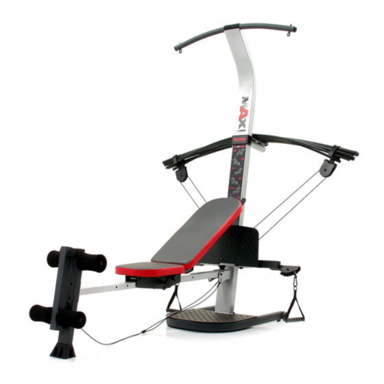
Model No. 831.15396.0
Serial No.
Write the serial number in the
space above for future reference.
Serial Number Decal (under seat)
Visit our website at
www.weiderfitness.com
CAUTION
Read all precautions and instruc-
tions in this manual before
using this equipment. Save this
manual for future reference.
RESISTANCE SYSTEM EXERCISER
Sears, Roebuck and Co., Hoffman Estates, IL 60179
User's Manual
Advertisement
Table of Contents

Related Manuals for Weider 831.15396.0


Summary of Contents for Weider 831.15396.0
- Page 1 Model No. 831.15396.0 Serial No. Write the serial number in the space above for future reference. Serial Number Decal (under seat) RESISTANCE SYSTEM EXERCISER Visit our website at User’s Manual www.weiderfitness.com CAUTION Read all precautions and instruc- tions in this manual before using this equipment.
-
Page 2: Table Of Contents
TABLE OF CONTENTS WARNING DECAL PLACEMENT ............. 2 IMPORTANT PRECAUTIONS . -
Page 3: Important Precautions
8. Always wear athletic shoes for foot protection with the included resistance, and the resist- while exercising. ance included with a MAX by WEIDER MAX PACK. Do not use the resistance system with 9. The top frame is not designed to be used for any other type of resistance. -
Page 4: Before You Begin
Whether calling. The model number is 831.15396.0. The serial your goal is to tone your body, build dramatic muscle number can be found on a decal attached to the resist-... -
Page 5: Assembly
ASSEMBLY • Tighten all parts as you assemble them, unless Make Things Easier for Yourself instructed to do otherwise. This manual is designed to ensure that the resist- • As you assemble the resistance system, make ance system can be assembled successfully by sure all parts are oriented as shown in the draw- most people. - Page 6 2. Attach a Wheel (31) to the outside of the Base (1) with an M10 x 108mm Bolt (81), three M10 Washers (75), and an M10 Nylon Locknut (76). Do not overtighten the Locknut; the Wheel must be able to turn easily. Attach the other Wheel (not shown) in the same manner.
- Page 7 6. Attach the Lat Tower (4) to the Upright (3) with four M10 x 25mm Button Head Bolts (87), and four M10 Lock Washers (103). Attach the Name Plate (89) to the Lat Tower (4) with two M4 x 16mm Screws (62). 7.
- Page 8 9. Attach two 8mm Metal Spacers (97), a 60mm Metal Spacer (39), and two Bearing Wheels (46) to one end of the Seat Carriage (12) with an M8 x 104mm Bolt (60) and an M8 Nylon Locknut (65) as shown. Make sure the parts are oriented as Attach second set of wheels shown in the inset drawing;...
- Page 9 12. Press two 25mm Square Inner Caps (54) into the indicated end of the Backrest Frame (15). Attach a Plastic Foot (53) to the Backrest Frame (15) with an M4 x 16mm Screw (62). Attach the two Guard Plates (17) to the inside of the Backrest Frame (15) with four M4 x 16mm Screws (62).
- Page 10 16. Locate the Fulcrum (18) on the Lat Tower (4) (see the inset drawing). Slide the Tray (35) onto the Edges rods on the Fulcrum. Make sure the Tray is ori- ented as shown in the drawing. Set the Resistance Bars into the Tray (35) in the following order: the 10-pound Removable Resistance Bar (67), the 20-pound Removable Resistance Bar (36), an 80-pound Resistance Bar...
- Page 11 20. Wrap the Long Cable (80) under a 90mm Pulley (28) as shown. Attach the Pulley and a Pulley Guard (29) to the Upright (3) with an M10 x 113mm Button Head Bolt (40) and an M10 Nylon Locknut (76). Make sure the flat edge of the Pulley Guard is on the bottom.
-
Page 12: Cable Diagram
24. Locate the Leg Lever Cable (32), which has two ends that are the same length and a third end that is longer. Route the longest end of the Leg Lever Cable (32) through the hole in the Front Leg (6), and attach it inside of the hole in the Leg Lever (7) with an M10 x 60mm Button Head Bolt (63) and an M10 Nylon Locknut (76). -
Page 13: Adjustments
ADJUSTMENTS This section explains how to adjust the resistance system. See the EXERCISE GUIDELINES on page 17 for important information about how to get the most benefit from your exercise program. Also, refer to the accompa- nying exercise guide to see the correct form for each exercise. Make sure all parts are properly tightened each time the resistance system is used. - Page 14 ATTACHING THE ACCESSORIES To attach a Short Handle (49) to a high pulley, first attach the high pulley to the resistance system (see ATTACHING THE HIGH PULLEYS AND LEG LEVER on page 13). Then, attach the Short Handle to the Short Cable (33) with a Cable Clip (51).
-
Page 15: Adjusting The Backrest
ADJUSTING THE BACKREST The Backrest (14) can be used in a level position or one of three inclined positions. To use the Backrest in a level position, secure the Seat Carriage (12) to the Slot adjustment hole in the Bench Rail (5) next to the Front Leg (6) (see ADJUSTING THE SEAT on page 13). -
Page 16: Cable Diagram
USING THE REMOVABLE RESISTANCE BARS The Removable Resistance Bars (36, 67) can be used to exercise apart from the resistance system, as shown in the video or on the exercise guide. To remove a Resistance Bar, pull it out of the Tray (35). To replace the Removable Resistance Bars (36, 67), slide them into the Tray (35) from the side shown, so that the arrows on the rings point toward the Tray. -
Page 17: Exercise Guidelines
EXERCISE GUIDELINES THE FOUR BASIC TYPES OF WORKOUTS PERSONALIZING YOUR EXERCISE PROGRAM Muscle Building Determining the exact length of time for each workout, To increase the size and strength of your muscles, as well as the number of repetitions or sets completed, push them close to their maximum capacity. -
Page 18: Muscle Chart
Rest for a short period of time after each set. The slowly as you stretch and do not bounce. Ease into ideal resting periods are: each stretch gradually and go only as far as you can • Rest for three minutes after each set for a muscle without strain. - Page 19 EXERCISE RESISTANCE SETS REPS MONDAY Date: AEROBIC EXERCISE TUESDAY Date: EXERCISE RESISTANCE SETS REPS WEDNESDAY Date: THURSDAY AEROBIC EXERCISE Date: EXERCISE RESISTANCE SETS REPS FRIDAY Date: Make photocopies of this page for scheduling and recording your workouts.
-
Page 20: Part Identification Chart
PART IDENTIFICATION CHART Refer to the drawings below to identify small parts used in assembly. The number in parentheses below each drawing is the key number of the part, from the PART LIST on the reverse side of this page. Note: Some small parts may have been pre-attached. - Page 21 M10 x 65mm Button Head Bolt (70) M10 x 60mm Button Head Bolt (63) M10 x 68mm Button Head Bolt (56) M10 x 53mm Carriage Bolt (61) 1/4” x 45mm Bolt (58) M10 x 66mm Carriage Bolt (83) M10 x 72mm Bolt (64) M10 x 42mm Button Head Bolt (71) M10 x 91mm Bolt (90) M10 x 25mm Button Head Bolt (87)
-
Page 22: Part List
PART LIST—Model No. 831.15396.0 R1005A Key No. Qty. Description Key No. Qty. Description Base M8 x 114mm Axle Base Plate 1/4” x 45mm Bolt Upright M8 Washer Lat Tower M8 x 104mm Bolt Bench Rail M10 x 53mm Carriage Bolt... - Page 23 EXPLODED DRAWING—Model No. 831.15396.0 R1005A 53 62 89 62...
-
Page 24: Warranty
WARRANTY For one year from the date of purchase, if failure occurs due to defect in material or workmanship in this RESISTANCE SYSTEM EXERCISER, contact the nearest Sears Service Center throughout the United States and Sears will repair or replace the RESISTANCE SYSTEM EXERCISER, free of charge. Parts will be replaced for five years.