Table of Contents

Related Manuals for Pro-Form Activator V7


Summary of Contents for Pro-Form Activator V7
- Page 1 -lr| Model No. 83t.14787.0 Serial No. USER'S MANUAL Write the serial number in the space above for reference, Serial Number Decal • Assembly • Operation • Troubleshooting • Part List and Drawing Sears, Roebuck and Co., Hoffman Estates, IL 60179...
-
Page 2: Warning Decal Placement
TABLE OF CONTENTS WARNING DECAL PLACEMENT .............. IMPORTANT PRECAUTIONS ..............BEFORE YOU BEGIN ..............PART IDENTIFICATION CHART .............. ASSEMBLY ................HOW TO USE THE VIBRATION PLATFORM ........... TROUBLESHOOTING ..............PART LIST ................EXPLODED DRAWING ..............ORDERING REPLACEMENT PARTS ..........Back Cover 90 DAY FULL WARRANTY ............ -
Page 3: Important Precautions
IMPORTANT PRECAUTIONS... -
Page 5: Before You Begin
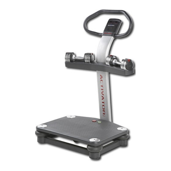
BEFORE YOU BEGIN Thank you for selecting the revolutionary PROFORM ® cover of this manual. To help us assist you, note the ACTIVATOR V7 vibration platform. The ACTIVATOR product model number and serial number before con- V7 vibration platform offers whole body vibration tacting us. -
Page 6: Part Identification
PART IDENTIFICATION CHART See the drawings below to identify small parts used in assembly, The number in parentheses by each drawing is the key number of the part, from the PART LIST near the end of this manual. Note: Some small parts may have been preattached. - Page 7 ASSEMBLY • For help identifying small parts, see the PART IDENTIFICATION CHART on page 6. • Tighten all parts as you assemble them, unless instructed to do otherwise. • Assembly may require the following tools (not included): one adjustable wrench Before beginning assembly, carefully read the following information and instructions: one rubber mallet...
- Page 8 2. Tip: Be careful not to pinch the wires during this step. With the help of a second person, carefully tip the Base (5) onto its side. Attach the Lower Upright (1) to the Base (5) with two M10 x 55mm Patch Screws (20), two M10 Split Washers (38), two M10 x 68ram Bolts (55), and two M10 Nylon Locknuts (32).
- Page 9 Attach the Weight Rest (42) to the Weight Rest Frame (41) with eight M5 x 38ram Screws (40). Do not tighten the Screws yet. Locate the wire tie inside the Upper Upright (36). Insert the wire tie through the hole in the Weight Rest Frame (41).
- Page 10 8. Tip: Be careful not to pinch the wires during this step. Attach the Upper Upright (36) to the Lower Upright (1) with four M10 x 20mm Patch Screws (28) and four M!0 Split Washers (38). See step 5. Tighten the eight M5 x 38ram Screws (40).
- Page 11 11. Attach the back of the Console (3) to the Upper Upright (36) with two M4 x 16mm Patch Screws (26). Do not tighten the Screws yet. 12. While a second person holds the Front of the Console (3) near the Upper Upright (36), con- nect the console ground wire to the Ground Wire (52).
- Page 12 14. Set ten weight plates into the indicated slots in the right side of the Weight Rest (42). Next, lift the two selector pins on a Dumbbell (44), and slide the selector pins to the adjustment holes Selector marked "2.5." Place the Dumbbell on the weight ,Pins plates.
-
Page 13: How To Use The Vibration Platform
HOW TO USE THE VIBRATION PLATFORM HOW TO MOVE THE VIBRATION PLATFORM Before moving the vibration platform, unplug the power cord and remove the dumbbells from the weight rest. Hold the handlebar and place one foot against the wheel. Tilt the vibration platform until it rolls freely on the wheel. - Page 14 HOW TO PLUG IN THE POWER CORD This product is for use on a nominal 12g-volt circuit, and has a grounding plug that looks like the plug illus- trated in drawing 1 below. Atemporary adapter that looks like the adapter illustrated in drawing 2 may be used to connect the surge suppressor to a 2-pole receptacle as shown in drawing 2 if a properly grounded outlet is not available.
- Page 15 CONSOLE DIAGRAM CONSOLE FEATURES you do not do this, the console or other electronic components may become damaged. The console offers a selection of features designed to make your workouts more effective and enjoyable. Plug the power cord You can change the time and frequency of your vibra- into the receptacle on tion sessions with the touch of a button, the base of the vibra-...
- Page 16 HOW TO USE THE MANUAL MODE HOW TO USE AN IFIT PROGRAM Turn on the power. 1. Turn on the power. See HOW TO TURN ON THE POWER on page See HOW TO TURN ON THE POWER on page Select the desired vibration time. Insert an iFIT card and select a program.
-
Page 17: Troubleshooting
TROUBLESHOOTING Inspect all parts of the vibration platform regularly. Replace any worn parts immediately. Outer surfaces of the vibra- tion platform can be cleaned with a damp cloth and a mild, non-abrasive detergent; do not use solvents to clean the vibration platform. Most vibration platform problems can be solved by following the simple steps below. - Page 18 PART LIST--Model No. 831.14787.0 Ro4o8A Key No. Qty. Description Key No. Qty. Description Lower Upright M10 Nylon Locknut Platform Cover M10 x 114mm Bolt Console M10 x 35mm Screw Platform Plate Wheel Bracket Base Upper Upright Vibration Platform M10 x 62mm Patch Screw Stop Button M10 Split Washer Start Button...
-
Page 19: Exploded Drawing
EXPLODED DRAWING-- Model No. 831.14787.0 Ro4oaA 26 _52... -
Page 20: 90 Day Full Warranty
Your Home For repair--in your home--of all major brand appliances, lawn and garden equipment, or heating and cooling systems, no matter who made it, no matter who sold it! For the replacement parts, accessories, and user's manuals that you need to do-it-yourself. For Sears professional installation of home appliances...