Table of Contents
Advertisement
Advertisement
Table of Contents

Related Manuals for Asus MAXIMUS III FORMULA


Summary of Contents for Asus MAXIMUS III FORMULA
- Page 1 Maximus III Formula...
- Page 2 Product warranty or service will not be extended if: (1) the product is repaired, modified or altered, unless such repair, modification of alteration is authorized in writing by ASUS; or (2) the serial number of the product is defaced or missing.
-
Page 3: Table Of Contents
Contents Notices ....................... viii Safety information ..................ix About this guide ..................xi Maximus III Formula specifications summary ........xiii Chapter 1: Product introduction Welcome! ..................1-1 Package contents ................. 1-1 Special features ................1-2 1.3.1 Product highlights ............1-2 1.3.2... - Page 4 BIOS setup Managing and updating your BIOS ..........3-1 3.1.1 ASUS Update utility ............3-1 3.1.2 ASUS EZ Flash 2 utility ........... 3-4 3.1.3 ASUS CrashFree BIOS 3 utility ........3-5 BIOS setup program ..............3-6 3.2.1 BIOS menu screen ............3-7 3.2.2...
- Page 5 Contents 3.3.5 Intel(R) SpeedStep(TM) Tech [Enabled] ....... 3-10 3.3.6 Intel(R) TurboMode Tech [Enabled] ......3-10 3.3.7 BCLK Frequency [XXX] ..........3-11 3.3.8 PCIE Frequency [XXX] ..........3-11 3.3.9 QPI Frequency [Auto] ............3-11 3.3.10 DRAM Frequency [Auto] ..........3-11 3.3.11 DRAM Timing Control ............3-11 3.3.12 CPU Clock Amplitude [Auto] .........
- Page 6 GO_Button File ............. 3-42 3.8.4 AI NET 2................ 3-42 3.8.5 MemPerfect ..............3-43 3.8.6 ASUS EZ Flash 2 ............3-43 Exit menu ..................3-44 Chapter 4: Software support Installing an operating system ........... 4-1 Support DVD information ............4-1 4.2.1 Running the support DVD ..........
- Page 7 4.2.8 Other information ............4-7 Software information ..............4-9 4.3.1 Sound Blaster X-Fi audio utility ........4-9 4.3.2 ASUS PC Probe II ............4-13 4.3.3 ASUS AI Suite ............... 4-19 4.3.4 ASUS Fan Xpert ............4-21 4.3.5 ASUS EPU-6 Engine ............ 4-22 4.3.6...
-
Page 8: Notices
Canadian Department of Communications. This class B digital apparatus complies with Canadian ICES-003. REACH Complying with the REACH (Registration, Evaluation, Authorization, and Restriction of Chemicals) regulatory framework, we published the chemical substances in our products at ASUS website at http://green.asus.com/english/ REACH.htm. viii... -
Page 9: Safety Information
Safety information Electrical safety • To prevent electrical shock hazard, disconnect the power cable from the electrical outlet before relocating the system. • When adding or removing devices to or from the system, ensure that the power cables for the devices are unplugged before the signal cables are connected. If possible, disconnect all power cables from the existing system before you add a device. - Page 10 Operation safety • Before installing the motherboard and adding devices on it, carefully read all the manuals that came with the package. • Before using the product, ensure all cables are correctly connected and the power cables are not damaged. If you detect any damage, contact your dealer immediately.
-
Page 11: About This Guide
Refer to the following sources for additional information and for product and software updates. ASUS websites The ASUS website provides updated information on ASUS hardware and software products. Refer to the ASUS contact information. Optional documentation Your product package may include optional documentation, such as warranty flyers, that may have been added by your dealer. -
Page 12: Conventions Used In This Guide
Conventions used in this guide To ensure that you perform certain tasks properly, take note of the following symbols used throughout this manual. DANGER/WARNING: Information to prevent injury to yourself when trying to complete a task. CAUTION: Information to prevent damage to the components when trying to complete a task. -
Page 13: Maximus Iii Formula Specifications Summary
CPUs. characteristics of individual CPUs. * Supports Intel Extreme Memory Profile (XMP) ® * Please refer to www.asus.com or user manual for the Memory ��L(�ualified �endors List). Memory ��L(�ualified �endors List). Expansion Slots 3 x PCIe x16 slot - 2 x PCIe 2.0 (red) support single at x16 or dual at x8... - Page 14 ASUS MyLogo3 ASUS Fan Xpert ASUS EZ Flash 2 ASUS CrashFree BIOS 3 ASUS Q-Connector ASUS Q-LED (CPU, DRAM, VGA, Boot Device LED) ASUS Q-Slot ASUS Q-DIMM BIOS Features 16Mb AMI BIOS, PnP, DMI2.0, WfM2.0, SM BIOS 2.4, ACPI2.0a Multi-Language BIOS...
- Page 15 Maximus III Formula specifications summary Internal I/O Connectors 3 x USB 2.0 connectors support additional 5 USB 2.0 ports (1 port reserved for ROG Connect @ rear) 10 x SATA connectors: 2 x Speeding HDD SATA connectors (Red) / 2 x SATA_ODD (White) / 6 x...
-
Page 17: Chapter 1: Product Introduction
This chapter describes the motherboard features and the new technologies it supports. Chapter 1: Product introduction... - Page 18 Chapter summary Welcome! ..................1-1 Package contents ................. 1-1 Special features ................1-2 ROG Maximus III Formula...
-
Page 19: Welcome
Welcome! Thank you for buying an ROG Maximus III Formula motherboard! The motherboard delivers a host of new features and latest technologies, making it another standout in the long line of ASUS quality motherboards! Before you start installing the motherboard, and hardware devices on it, check the items in your package with the list below. -
Page 20: Special Features
Green ASUS This motherboard and its packaging comply with the European Union’s Restriction on the use of Hazardous Substances (RoHS). This is in line with the ASUS vision of creating environment-friendly and recyclable products/packaging to safeguard consumers’ health while minimizing the impact on the environment. -
Page 21: Rog Intelligent Performance & Overclocking Features
MemPerfect optimizing your memory performance is a simple matter of selecting the frequency you desire, and letting MemPerfect do the rest! MemPerfect quickly checks your memory settings for errors and automatically fixes them—ensuring system stability and maximum efficiency. ROG Maximus III Formula... - Page 22 Speeding HDD Wait less. Play more! Double your hard disk drive performance easily and affordably with Speeding HDD, a remarkable ROG feature that utilizes a dual channel design to enhance HDD transfer rates. Wait less, play more! iROG Intelligent multiple control at hand iROG is a special IC which enables several ROG highlighted functions that give you full disposal of the motherboard at any stage! This design allows advanced user control and management to be processed at a hardware level.
-
Page 23: Rog Unique Features
ROG. The SupremeFX X-Fi features unique audio innovations for gamers to spot enemies in 3D environment during game play. SupremeFX X-Fi also provides gamers a special tool to emphasize human voices in games to help make dialogues clearer and more audible. ROG Maximus III Formula... -
Page 24: Asus Special Features
1.3.4 ASUS special features ASUS EZ DIY ASUS EZ DIY feature collection provides you easy ways to install computer components, update the BIOS or back up your favorite settings. ASUS Q-Shield The specially designed ASUS �-Shield does without the usual “fingers”—... - Page 25 ASUS EPU System Level Energy Saving The new ASUS EPU - the world's first power saving engine, has been upgraded to a new 6 engine version, which provides total system power savings by detecting current PC loadings and intelligently moderating power in real-time. With auto...
- Page 26 Chapter 1: Product Introduction...
-
Page 27: Chapter 2: Hardware Information
This chapter lists the hardware setup procedures that you have to perform when installing system components. It includes description of the jumpers and Chapter 2: Hardware connectors on the motherboard. information... - Page 28 System memory ................. 2-13 Expansion slots ................2-22 Jumper ..................2-26 I/O shield and Audio card Installation ........2-27 Connectors ................. 2-29 Starting up for the first time ............2-43 2.10 Turning off the computer ............2-44 ROG Maximus III Formula...
-
Page 29: Before You Proceed
Before you install or remove any component, ensure that the ATX power supply is switched off or the power cord is detached from the power supply. Failure to do so may cause severe damage to the motherboard, peripherals, or components. ROG Maximus III Formula... -
Page 30: Onboard Leds
Onboard LEDs The motherboard comes with LEDs that indicate the voltage conditions of CPU, memory, and PCH. You may adjust the voltages in BIOS. There are also an LED for hard disk drive activity and an onboard switch for power status. For more information about voltage adjustment, refer to 3.3 Extreme Tweaker menu. - Page 31 The LED does not light up when there is no hard disk drive connected to the motherboard or when the hard disk drive does not function. ROG Maximus III Formula...
- Page 32 Power LED The motherboard comes with a power-on switch that lights up to indicate that the system is ON, in sleep mode, or in soft-off mode. This is a reminder that you should shut down the system and unplug the power cable before removing or plugging in any motherboard component.
-
Page 33: Motherboard Overview
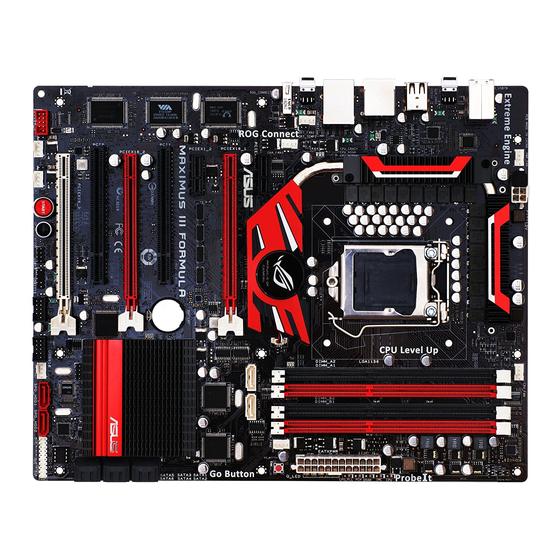
Motherboard overview 2.2.1 Motherboard layout ROG Maximus III Formula... -
Page 34: Supremefx X-Fi Audio Card Layout
2.2.2 SupremeFX X-Fi audio card layout 2.2.3 Layout contents Connectors/Jumpers/Switches/Slots Page CPU, chassis, and optional fan connectors (4-pin CPU_FAN; 2-35 4-pin PWR_FAN; 4-pin CHA_FAN1–2; 4-pin OPT_FAN1–3) ATX power connectors (24-pin EATXPWR, 8-pin EATX12V) 2-37 LGA1156 CPU Socket DDR3 DIMM slots 2-13 GO Button 2-42... -
Page 35: Placement Direction
Place nine (9) screws into the holes indicated by circles to secure the motherboard to the chassis. DO NOT overtighten the screws! Doing so can damage the motherboard. Place this side towards the rear of the chassis ROG Maximus III Formula... -
Page 36: Central Processing Unit (Cpu)
ASUS will shoulder the cost of repair only if the damage is shipment/transit-related. • Keep the cap after installing the motherboard. ASUS will process Return Merchandise Authorization (RMA) requests only if the motherboard comes with the cap on the LGA1156 socket. - Page 37 CPU notches. The CPU fits in only one correct orientation. DO NOT force the CPU Gold into the socket to prevent bending triangle mark the connectors on the socket and damaging the CPU! Alignment keys ROG Maximus III Formula...
- Page 38 Apply some Thermal Interface Material to the exposed area of the CPU that the heatsink will be in contact with, ensuring that it is spread in an even thin layer. Some heatsinks come with pre- applied thermal paste. If so, skip this step.
-
Page 39: Installing The Cpu Heatsink And Fan
Push down two fasteners at a time in a diagonal sequence to secure the heatsink and fan assembly in place. Orient the heatsink and fan assembly such that the CPU fan cable is closest to the CPU fan connector. ROG Maximus III Formula 2-11... -
Page 40: Uninstalling The Cpu Heatsink And Fan
Connect the CPU fan cable to the connector on the motherboard labeled CPU_FAN. DO NOT forget to connect the CPU fan connector! Hardware monitoring errors can occur if you fail to plug this connector. 2.3.3 Uninstalling the CPU heatsink and fan To uninstall the CPU heatsink and fan: Disconnect the CPU fan cable from the connector on the motherboard. -
Page 41: System Memory
The figure illustrates the location of the DDR3 DIMM sockets: Recommended memory configurations One DIMM: Install one memory module in DIMM_A1 slots as a single-channel operation. Two DIMMs (dual-channel operation): Four DIMMs (dual-channel operation): ROG Maximus III Formula 2-13... -
Page 42: Memory Configurations
2.4.2 Memory configurations You may install 1GB, 2GB and 4GB unbuffered and non-ECC DDR3 DIMMs into the DIMM sockets. • You may install varying memory sizes in Channel A and Channel B. The system maps the total size of the lower-sized channel for the dual-channel configuration. - Page 43 Maximus III Formula Motherboard Qualified Vendors Lists (QVL) DDR��21��MHz capability 3-2133MHz capability -2133MHz capability Vendor Part No. Size Chip NO. Timing Voltage DIMM socket support Dimm(Bios) (Optional) G.SKILL F3-17066CL9T-6GB-T 6144MB Heat-Sink Package 9-9-9-24 1.65 • • (Kit of 3) (1066-8-7-7-20) Maximus III Formula Motherboard Qualified Vendors Lists (QVL) DDR��2���MHz capability...
- Page 44 Maximus III Formula Motherboard Qualified Vendors Lists (QVL) DDR��1���MHz capability 3-1800MHz capability -1800MHz capability Vendor Part No. Size Chip NO. Timing Voltage DIMM socket Lable(Bios) support (Optional) Apacer 78.0AGCD-CDZ(XMP) 2048MB(Kit of 2) SS Heat-Sink Package 8-8-8-24 • • (1800-8-8-8-24) CORSAIR...
-
Page 45: Memory Configuration
• C*: Supports four modules inserted into both the yellow and black slots as two pairs of dual-channel memory configuration. Visit the ASUS website at www.asus.com for the latest QVL. ROG Maximus III Formula 2-17... - Page 46 Maximus III Formula Motherboard Qualified Vendors Lists (QVL) DDR��1���MHz capability 3-1333MHz capability -1333MHz capability Vendor Part No. Size Chip Chip NO. Timing Voltage DIMM socket Brand Dimm(Bios) support (Optional) A-DATA AD133301GOU 1024MB SS A-DATA AD30908C8D-15IG 1333-9-9-9-24 • • • A-DATA...
- Page 47 Maximus III Formula Motherboard Qualified Vendors Lists (QVL) DDR��1���MHz capability 3-1333MHz capability -1333MHz capability MICRON MT8JTF12864AY-1G4BYES 1024MB SS MICRON Z9HWR (1333-9-9-9-24) • • MICRON MT8JTF12864AZ-1G4F1 1024MB SS MICRON 9FF22 D9KPT 9(1066-8-8-8-20) • • • MICRON MT16JTF25664AZ-1G4F1 2048MB DS MICRON 9FF22 D9KPT 9(1066-8-8-8-20) •...
- Page 48 Maximus III Formula Motherboard Qualified Vendors Lists (QVL) DDR��1���MHz capability 3-1333MHz capability -1333MHz capability Patriot PVS34G1333LLK 4096MB DS N/A Heat-Sink Package 7-7-7-20 • • (Kit of 2) (1066-7-7-7-20) Patriot PVT36G1333ELK 6144MB DS N/A Heat-Sink Package 9-9-9-24 1.65 • • •...
-
Page 49: Installing A Dimm
Press the retaining clip outward to unlock the DIMM. Support the DIMM lightly with your fingers when pressing the retaining clip. The DIMM might get damaged when it flips out with extra force. Remove the DIMM from the socket. ROG Maximus III Formula 2-21... -
Page 50: Expansion Slots
Expansion slots In the future, you may need to install expansion cards. The following sub-sections describe the slots and the expansion cards that they support. Ensure to unplug the power cord before adding or removing expansion cards. Failure to do so may cause you physical injury and damage motherboard components. -
Page 51: Interrupt Assignments
– – – – 1394 Controller – – – – – – shared HD Audio – – – – – – shared – Onboard ATA controller II – – – shared – – – – ROG Maximus III Formula 2-23... -
Page 52: Pci Slot
2.5.4 PCI slot The PCI slot supports cards such as a LAN card, SCSI card, USB card, and other cards that comply with PCI specifications. Refer to the figure below for the location of the slot. 2.5.5 PCI Express x1 slots This motherboard supports PCI Express x1 network cards, SCSI cards and other cards that comply with the PCI Express specifications. - Page 53 We recommend that you provide sufficient power when running CrossFireX™ or SLI mode. See page 2-37 for details. • Connect a chassis fan to the motherboard connector labeled CHA_FAN1/2/3 when using multiple graphics cards for better thermal environment. ROG Maximus III Formula 2-25...
-
Page 54: Jumper
Jumper Clear RTC RAM (3-pin CLRTC_SW) This jumper allows you to enable the clr CMOS switch on the back I/O. You can clear the CMOS memory and system setup parameters by erasing the CMOS RTC RAM data. The clr CMOS switch on the back I/O helps you easily clear the system setup information such as system passwords. -
Page 55: I/O Shield And Audio Card Installation
I�O openings. Be cautious when installing the motherboard. The I/O shield edge springs may damage the I/O ports. The photos above are for reference only, the actual I/O shield may differ by models. ROG Maximus III Formula 2-27... -
Page 56: Audio Card Installation
2.7.2 Audio card Installation Take out the Audio card from the package. Locate the audio slot on the motherboard. Align the card connector with the slot and press firmly until the card sits on the slot completely. The photo below shows the audio card installed on the motherboard. -
Page 57: Connectors
ROG Connect switch USB 2.0 ports 7 and 8 USB 2.0 port 14 To use hot-plug, set the Controller Mode in the BIOS settings to [AHCI] mode. See section �.5.� Onboard Devices Configuration for details. ROG Maximus III Formula 2-29... -
Page 58: Lan Port Led Indications
* LAN port LED indications Activity/ Speed Speed LED Activity/Link Description Link LED Soft-off Mode Yellow Blinking During Power ON/OFF Yellow Blinking ORANGE 100 Mbps connection LAN port Yellow Blinking GREEN 1 Gbps connection **Audio 2, 4, 6, or ��channel configuration Headset Port 4-channel... -
Page 59: Internal Connectors
Serial ATA hard disk drives. The Serial ATA RAID feature is available only if you are using Windows XP SP2 or later versions. ® When using hot-plug and NCQ, set the Configure SATA as in the BIOS to • [AHCI]. See section �.4.5 Storage Configuration for details. ROG Maximus III Formula 2-31... - Page 60 JMicron JMB322 Serial ATA connectors ® (7-pin SPD_HDD1 [red], SPD_HDD2 [red]) These connectors are for the Serial ATA signal cables for Serial ATA hard disk drives. Connect Serial ATA hard disk drives to these ports if you want to create hardware RAID.
- Page 61 Never connect a 1394 cable to the USB connectors. Doing so will damage the motherboard! You can connect the USB cable to ASUS �-Connector (USB, blue) first, and then install the Q-Connector (USB) to the USB connector onboard. ROG connector (3-pin ROG) This connector is for the box (labeled as Republic of Gamers) on the heatpipe assembly.
- Page 62 GP connector (8-pin GP) This connector is for ASUS OC Station connection only. Connect one end Connect one end of the supplied data cable to the GP connector on the OC Station and the other end to this connector and USB13 on the motherboard to enjoy easier overclocking.
- Page 63 DO NOT place jumper caps on the fan connectors! If you install two VGA cards, we recommend that you plug the chassis fan cable to the motherboard connector labeled OPT_FAN1/2/3 for better thermal environment. ROG Maximus III Formula 2-35...
- Page 64 Thermal sensor cable connectors (2-pin OPT_TEMP1/2/3) These connectors are for temperature monitoring. Connect the thermal sensor cables to these connectors and place the other ends to the devices which you want to monitor temperature. The optional fan1/2/3 can work with the temperature sensors for a better cooling effect.
- Page 65 If you want to use two or more high-end PCI Express x16 cards, use a PSU with 1000W power or above to ensure the system stability. PSU suggested list PS U suggested list SilverStone ST1000 Seasonic SS-600HT Thermaltake W0083RE Thermaltake PUREPower-600AP Silverstone SST-ST75ZF EnerMAX EG701AX-VE (E)(24P) ROG Maximus III Formula 2-37...
- Page 66 11. System panel connector (20-8 pin PANEL) This connector supports several chassis-mounted functions. • System power LED (2-pin PLED) This 2-pin connector is for the system power LED. Connect the chassis power LED cable to this connector. The system power LED lights up when you turn on the system power, and blinks when the system is in sleep mode.
-
Page 67: Audio Connectors
Digital audio connector: This connector is for an additional Sony/Philips Digital Interface (S/PDIF) port(s). Front view Side view Optical drive audio connector Front panel audio connector Digital audio connector UPREME Listen with Absolutely HD ROG Maximus III Formula 2-39... - Page 68 13. ASUS Q-Connector (system panel) Use the ASUS Q-Connector to connect/disconnect the chassis front panel cables. To install the ASUS Q-Connector: Connect the front panel cables to the ASUS Q-Connector. Refer to the labels on the Q-Connector to know the detailed...
-
Page 69: Onboard Switches
This is ideal for overclockers and gamers who continually change settings to enhance system performance. Power-on switch Press the power-on switch to wake/power up the system. Reset switch Press the reset switch to reboot the system. ROG Maximus III Formula 2-41... - Page 70 GO button Press the GO button before POST to enable MemOK! or press it to quickly load the preset profile (GO_Button file) for temporary overclocking when in 2-42 Chapter 2: Hardware information...
-
Page 71: Starting Up For The First Time
No VGA detected short beeps One continuous beep followed by four Hardware component failure short beeps At power on, hold down the <Delete> key to enter the BIOS Setup. Follow the instructions in Chapter 3. ROG Maximus III Formula 2-43... -
Page 72: 2.10 Turning Off The Computer
2.10 Turning off the computer 2.10.1 Using the OS shut down function If you are using Windows Vista™: ® Click the Start button then select Shut Down. The power supply should turn off after Windows shuts down. ® If you are using Windows ®... -
Page 73: Chapter 3: Bios Setup
This chapter tells how to change the system settings through the BIOS Setup menus. Detailed descriptions of the BIOS parameters are also provided. BIOS setup... - Page 74 Managing and updating your BIOS ..........3-1 BIOS setup program ..............3-6 Extreme Tweaker menu ............... 3-9 Main menu .................. 3-16 Advanced menu ................. 3-21 Power menu ................3-29 Boot menu .................. 3-35 Tools menu ................. 3-39 Exit menu ..................3-45 ROG Maximus III Formula...
-
Page 75: Managing And Updating Your Bios
® ASUS EZ Flash 2 (Updates the BIOS using a floppy disk or USB flash disk.) ASUS CrashFree BIOS 3 utility: Restores the BIOS using the motherboard support D�D or a USB flash drive when the BIOS file fails or gets corrupted. - Page 76 To update the BIOS through the Internet: Launch the ASUS Update utility from the Windows desktop by clicking Start ® > Programs > ASUS > ASUSUpdate > ASUSUpdate. The ASUS Update main window appears. Select Update BIOS from the Select the ASUS FTP site nearest...
- Page 77 To update the BIOS through a BIOS file: Launch the ASUS Update utility from the Windows desktop by clicking Start ® > Programs > ASUS > ASUSUpdate > ASUSUpdate. The ASUS Update main window appears. Select Update BIOS from a file option from the drop-down menu, then click Next.
-
Page 78: Asus Ez Flash 2 Utility
3.1.2 ASUS EZ Flash 2 utility The ASUS EZ Flash 2 feature allows you to update the BIOS without having to use a DOS-based utility. The EZ Flash 2 utility is built in the BIOS chip so it is accessible by pressing <Alt> + <F2> during the Power-On Self Tests (POST). -
Page 79: Asus Crashfree Bios 3 Utility
3.1.3 ASUS CrashFree BIOS 3 utility The ASUS CrashFree BIOS 3 utility is an auto recovery tool that allows you to restore the BIOS file when it fails or gets corrupted during the updating process. You can restore a corrupted BIOS file using the motherboard support D�D or a USB flash drive that contains the BIOS file. -
Page 80: Bios Setup Program
The BIOS setup screens shown in this section are for reference purposes only, and may not exactly match what you see on your screen. • �isit the ASUS website at www.asus.com to download the latest BIOS file for this motherboard. Chapter 3: BIOS setup... -
Page 81: Bios Menu Screen
At the bottom right corner of a menu screen are the navigation keys for that particular menu. Use the navigation keys to select items in the menu and change the settings. Some of the navigation keys differ from one screen to another. ROG Maximus III Formula... -
Page 82: Menu Items
3.2.4 Menu items The highlighted item on the menu bar displays the specific items for that menu. For example, selecting Main shows the Main menu items. The other items (Advanced, Power, Boot, and Exit) on the menu bar have their respective menu items. -
Page 83: Extreme Tweaker Menu
[Auto] CPU Voltage Mode [VID] CPU Voltage [Auto] CPU PLL Voltage [Auto] IMC Voltage [Auto] Current Voltage: 1.058V PCH Temperature: 38˚C/100˚F PCH Voltage [Auto] Current Voltage: 1.535V DRAM Voltage [Auto] DRAM DATA REF Voltage on CHA [Auto] DRAM CTRL REF Voltage on CHA [Auto] DRAM DATA REF Voltage on CHB [Auto] DRAM CTRL REF Voltage on CHB [Auto] ←→ Select Screen ↑↓ Select Item Keyboard Tweakit Control [Disabled] +- Change Option F1 General Help ******** Spread Spectrum and Clock Skew ********* F10 Save and Exit CPU Spread Spectrum [Auto] ESC Exit PCIE Spread Spectrum [Auto] v02.61 (C)Copyright 1985-2009, American Megatrends, Inc. ROG Maximus III Formula... -
Page 84: Ai Overclock Tuner [Auto]
3.3.1 Ai Overclock Tuner [Auto] Allows selection of CPU overclocking options to achieve desired CPU internal frequency. Select either one of the preset overclocking configuration options: Manual Allows you to individually set overclocking parameters. Auto Loads the optimal settings for the system. X.M.P. -
Page 85: Bclk Frequency [Xxx]
DRAM RAS# ACT Time [Auto] Configuration options: [Auto] [3 DRAM Clock] [4 DRAM Clock] – [3� DRAM Clock] [31 DRAM Clock] DRAM RAS# to RAS# Delay [Auto] Configuration options: [Auto] [1 DRAM Clock] – [7 DRAM Clock] ROG Maximus III Formula 3-11... - Page 86 DRAM REF Cycle Time [Auto] Configuration options: [Auto] [3� DRAM Clock] [36 DRAM Clock] [48 DRAM Clock] [60 DRAM Clock] [72 DRAM Clock] [82 DRAM Clock] [88 DRAM Clock] [90 DRAM Clock] [100 DRAM Clock] [110 DRAM Clock] DRAM WRITE Recovery Time [Auto] Configuration options: [Auto] [1 DRAM Clock] –...
-
Page 87: Cpu Clock Amplitude [Auto]
CPU Clock Skew item at the same time. Configuration options: [Auto] [Normal] [Delay 1��ps]–[Delay 15��ps] 3.3.16 Extreme OV [Disabled] [Enabled] Enables the Extreme OV function. [Disabled] Disables this function. 3.3.17 Full Phase Control [HW TEST] Configuration options: [HW TEST] ROG Maximus III Formula 3-13... -
Page 88: Cpu Load-Line Calibration [Auto]
3.3.18 CPU Load-Line Calibration [Auto] Load-Line Calibration [Auto] Allows you to select the CPU Load-Line mode. [Auto] BIOS automatically adjust the voltage. [Disabled] Follows Intel specifications. [Enabled] Improve CPU VDroop directly. 3.3.19 CPU Voltage Mode [Offset] Allows you to set the CPU �oltage Mode. Configuration options: [Offset] [�ID] 3.3.20 CPU Voltage [Auto] Allows you to set the CPU VCore voltage. -
Page 89: Dram Voltage [Auto]
CPU Spread Spectrum [Auto] [Disabled] Enhances the BCLK overclocking ability. [Auto] Sets to [Auto] for EMI control. 3.3.29 PCIE Spread Spectrum [Auto] [Disabled] Enhances the PCIE overclocking ability [Auto] Sets to [Auto] for EMI control. ROG Maximus III Formula 3-15... -
Page 90: Main Menu
Main menu When you enter the BIOS Setup program, the Main menu screen appears, giving you an overview of the basic system information. Refer to section 3.2.1 BIOS menu screen for information on the menu screen items and how to navigate through them. BIOS SETUP UTILITY Extreme Tweaker Main Advanced Power Boot Tools Exit Use [ENTER], [TAB]... -
Page 91: Sata 1-6
Enables or disables the LBA (Logical Block Addressing) mode. [Auto] Select [Auto] to enable the LBA mode (Logical Block Addressing mode) if the device supports this mode, and if the device was not previously formatted with LBA mode disabled. [Disabled] Disable this function. ROG Maximus III Formula 3-17... - Page 92 Block (Multi-Sector Transfer) M [Auto] Enables or disables data multi-sectors transfers. [Auto] When set to [Auto], the data transfer from and to the device occurs multiple sectors at a time if the device supports multi-sector transfer feature. [Disabled] When set to [Disabled], the data transfer from and to the device occurs one sector at a time.
-
Page 93: Storage Configuration
Disables or enables device write protection. This will be effective only if the device is accessed through BIOS. Configuration option: [Disabled] [Enabled] IDE Detect Time Out (Sec) [35] Selects the time out value for detecting ATA�ATAPI devices. Configuration options: [0] [5] [10] [15] [20] [25] [30] [35] ROG Maximus III Formula 3-19... -
Page 94: Ahci Configuration
�.4.6 AHCI Configuration This menu is the section for AHCI configuration. It appears only when you set the item Configure SATA as from the sub-menu of SATA Configuration to [AHCI]. BIOS SETUP UTILITY Main AHCI Settings While entering setup, BIOS auto detects SATA Port1 [Not Detected] the presence of SATA Port2 [Not Detected] SATA devices. This SATA Port3 [Not Detected] displays the status SATA Port4 [Not Detected] of auto detection of... -
Page 95: Advanced Menu
ESC Exit Max CPUID Value Limit [Disabled] v02.61 (C)Copyright 1985-2009, American Megatrends, Inc. Scroll down to display the following items: Intel(R) Virtualization Tech [Enabled] CPU TM Function [Enabled] Execute-Disable Bit Capability [Enabled] ←→ Select Screen Intel(R) HT Technology [Enabled] Active Processor Cores [All] ↑↓ Select Item +- Change Option A20M [Disabled] F1 General Help Intel(R) SpeedStep(TM) Tech [Enabled] F10 Save and Exit Intel(R) Turbo Mode Tech [Enabled] ESC Exit Intel(R) C-STATE Tech [Disabled] v02.61 (C)Copyright 1985-2009, American Megatrends, Inc. ROG Maximus III Formula 3-21... - Page 96 CPU Ratio Setting [Auto] Allows you to adjust the ratio between CPU Core Clock and BCLK Frequency. Use the <+> and <-> keys to adjust the value. The valid value ranges differently according to your CPU model. C1E Support [Disabled] [Enabled] Enables the C1E support function.
- Page 97 This item appears only when you set the Intel(R) C-STATE Tech item to [Enabled]. We recommend that you set this item to [Auto] for BIOS to automatically detect the C-State mode supported by your CPU. Configuration options: [Auto] [C1] [C3] [C6] ROG Maximus III Formula 3-23...
-
Page 98: Chipset
3.5.2 Chipset The Chipset menu allows you to change the advanced chipset settings. Select an item then press <Enter> to display the sub-menu. BIOS SETUP UTILITY Advanced Advanced Chipset Settings Configure North Bridge features WARNING: Setting wrong values in below sections may cause system to malfunction. North Bridge Configuration North Bridge Configuration BIOS SETUP UTILITY Advanced North Bridge Chipset Configuration Set the ECC options for cache and dram... -
Page 99: Onboard Device Configuration
AHCI (Advabced Host Controller Interface). The AHCI allows the onboard storage driver to enable advanced Serial ATA features that increases storage performance on random workloads by allowing the drive to internally optimize the order of commands. ROG Maximus III Formula 3-25... -
Page 100: Usb Configuration
�.5.4 USB Configuration The items in this menu allows you to change the USB-related features. Select an item then press <Enter> to display the configuration options. BIOS SETUP UTILITY Advanced USB Configuration Enable support for all USB ports. Module Version - 2.24.3-13.4 USB Devices Enabled: 2 Hubs USB Functions [Enabled] Legacy USB Support [Auto] BIOS EHCI Hand-off [Enabled] The USB Devices Enabled item shows the auto-detected values. -
Page 101: Led Control
Configuration options: [Enabled] [Disabled] CPU LED Selection [CPU] Allows you to switch the onboard CPU LED display between CPU voltage [CPU], CPU PLL voltage [CPU PLL] and IMC voltage [IMC]. Configuration options: [CPU] [CPU PLL] [IMC] ROG Maximus III Formula 3-27... -
Page 102: Irog Configuration
�.5.6 iROG Configuration BIOS SETUP UTILITY Advanced iROG Configuration iROG Timer Keeper System will record iROG ID_Number Information using time every 1 iROG_1 ID_Number: 54 minute iROG_2 ID_Number: 9 iROG Timer Keeper [Last State] Current Operation time: Total Operation time: ←→ Select Screen ↑↓ Select Item F1 General Help F10 Save and Exit ESC Exit v02.61 (C)Copyright 1985-2009, American Megatrends, Inc. iROG Timer Keeper [Last State] Allows you to set the iROG Time Keeper operation mode. Configuration options: [Last State] [Disabled] [Enabled] 3.5.7 ROG Connect BIOS SETUP UTILITY... -
Page 103: Power Menu
ACPI 2.0 Support [Disabled] [Disabled] When set to [Disabled], the system will not add additional tables as per ACPI 2.� specifications. [Enabled] When set to [Enabled], the system adds additional tables as per ACPI 2.� specifications. ROG Maximus III Formula 3-29... -
Page 104: Apm Configuration
3.6.4 ACPI APIC Support [Enabled] Allows you to enable or disable the Advanced Configuration and Power Interface (ACPI) support in the Advanced Programmable Interrupt Controller (APIC). [Disabled] When set to [Disabled], the system disable the Advanced Configuration and Power Interface (ACPI) support in the Advanced Programmable Interrupt Controller (APIC). - Page 105 Sets specific keys on the PS�2 keyboard to turn on the system. Sets specific keys on the PS�2 keyboard to turn on the system. This feature requires an ATX power supply that provides at least 1A on the +5VSB lead. . ROG Maximus III Formula 3-31...
-
Page 106: Hardware Monitor
3.6.7 Hardware Monitor BIOS SETUP UTILITY Advanced Hardware Monitor Voltage Monitor Voltage Monitor Temperature Monitor FAN Speed Monitor FAN Speed Control ←→ Select Screen ↑↓ Select Item F1 General Help F10 Save and Exit ESC Exit v02.61 (C)Copyright 1985-2009, American Megatrends, Inc. Voltage Monitor CPU �oltage; CPU PLL �oltage; PCH �oltage; IMC �oltage; DRAM �oltage; DRAM Termination �oltage; 3.3� �oltage; 5� �oltage; 12� �oltage The onboard hardware monitor automatically detects the voltage output through the onboard voltage regulators. -
Page 107: Fan Speed Control
Set to [Turbo] to achieve maximum CPU fan speed. Chassis Q-Fan Function [Disabled] Allows you to enable or disable the Chassis fan controller. [Disabled] Disables the Chassis Q-fan controller. [Enabled] Enables the Chassis Q-fan controller. ROG Maximus III Formula 3-33... - Page 108 The Chassis Fan Profile item appears when you enable the Chassis Q-Fan Function feature. Chassis Fan Profile [Standard] This item appears only when you enable the Chassis Q-Fan Control feature and allows you to set the appropriate performance level of the chassis fan. [Standard] Sets to [Standard] to make the chassis fan automatically adjust depending on the chassis temperature.
-
Page 109: Boot Menu
These items specify the boot device priority sequence from the available devices. The number of device items that appears on the screen depends on the number of devices installed in the system. Configuration options: [xxx Drive] [Disabled] ROG Maximus III Formula 3-35... -
Page 110: Boot Settings Configuration
Enables the full screen logo display feature. [Disabled] Disables the full screen logo display feature. Set this item to [Enabled] to use the ASUS MyLogo3™ feature. AddOn ROM Display Mode [Force BIOS] Sets the display mode for option ROM. [Force BIOS] [Keep Current] . -
Page 111: Security
<Enter>. The message “Password Uninstalled” appears. If you forget your BIOS password, you can clear it by erasing the CMOS Real Time Clock (RTC) RAM. See section 2.6 Jumper for information on how to erase the RTC RAM. ROG Maximus III Formula 3-37... -
Page 112: Change User Password
After you have set a supervisor password, the other items appear to allow you to change other security settings. BIOS SETUP UTILITY Boot Security Settings <Enter> to change password. Supervisor Password :Installed <Enter> again to User Password :Installed disabled password. Change Supervisor Password User Access Level [Full Access] Change User Password Password Check [Setup] User Access Level [Full Access] This item allows you to select the access restriction to the Setup items. -
Page 113: Tools Menu
This item appears only when you select a Speeding HDD mode to update and displays the Speeding HDDt mode that you have changed. Ultra Space This item appears only when you have created a drive partition using the Ultra Space function. ROG Maximus III Formula 3-39... -
Page 114: Asus O.c. Profile
SPD_HDD1 (red) and SPD_HDD1 (red) connectors on the and SPD_HDD1 (red) connectors on the SPD_HDD1 (red) connectors on the connectors on the motherboard. �.�.2 ASUS O.C. Profile This item allows you to store or load multiple BIOS settings. BIOS SETUP UTILITY Tools O.C. PROFILE Configuration Typing your profile name, [0-9][a-z][A-Z] O.C. - Page 115 DO NOT shut down or reset the system while updating the BIOS to prevent the system boot failure! • We recommend that you update the BIOS file only coming from the same memory�CPU configuration and BIOS version. • Only the CMO file can be loaded. ROG Maximus III Formula 3-41...
-
Page 116: Go_Button File
3.8.3 GO_Button File This menu allows you to set the GO_Button files, and load the desired GO_Button file. BIOS SETUP UTILITY Tools GO_Button File Save GO_Button File Save File to: [None] Load File From: [None] FSB Frequency Controller [Auto] CPU Voltage [Auto] CPU PLL Voltage [Auto] IMC Voltage [Auto] PCH Voltage [Auto] DRAM Voltage [Auto] ←→ Select Screen ↑↓ Select Item +- Change Option... -
Page 117: Memperfect
Configuration options: [Disabled] [Enabled] 3.8.6 ASUS EZ Flash 2 Allows you to run ASUS EZ Flash 2. When you press <Enter>, a confirmation message appears. Use the left/right arrow key to select between [Yes] or [No], then press <Enter> to confirm your choice. -
Page 118: Exit Menu
Exit menu The Exit menu items allow you to load the optimal or failsafe default values for the BIOS items, and save or discard your changes to the BIOS items. BIOS SETUP UTILITY Main Extreme Tweaker Advanced Power Boot Tools Exit Exit system setup after Exit Options saving the changes. F10 key can be used for Exit & Save Changes this operation. Exit & Discard Changes Discard Changes Load Setup Defaults ←→ Select Screen ↑↓ Select Item... -
Page 119: Chapter 4: Software Support
This chapter describes the contents of the support DVD that comes with the motherboard package and the software. Software support... - Page 120 Chapter summary Installing an operating system ........... 4-1 Support DVD information ............4-1 Software information ..............4-9 RAID configurations ..............4-27 Creating a RAID driver disk ............4-32 ROG Maximus III Formula...
-
Page 121: Installing An Operating System
The contents of the support DVD are subject to change at any time without notice. Visit the ASUS website at www.asus.com for updates. 4.2.1 Running the support DVD Place the support DVD to the optical drive. -
Page 122: Drivers Menu
Installs the Sound Blaster X-Fi driver. JMicron JMB36X Controller Driver Installs the JMicron controller driver. ® ASUS TurboV EVO Installs ASUS TurboV, the advanced overclocking tool for extreme O.C. record. ASUS EPU-6 Engine Installs ASUS EPU-6 Engine driver and utility. Chapter 4: Software support... -
Page 123: Utilities Menu
The anti-virus application scans, identifies, and removes computer viruses. �iew the online help for detailed information. Speeding HDD ASUS Speeding HDD helps secure data on the hard drives and enhance the hard drive performance. ASUS PC Probe II This smart utility monitors the fan speed, CPU temperature, and system voltage, and alerts you of any detected problems. - Page 124 ASUS AI Direct Link The ASUS AI Direct Link provides up to 7�% transferring speed improvement when compared to traditional USB 2.0 and is the easiest and fastest way for users to enjoy large-sized data exchange of files such as movies, music, etc.
-
Page 125: Make Disk Menu
The Manuals menu contains a list of supplementary user manuals. Click an item to open the folder of the user manual. Most user manual files are in Portable Document Format (PDF). Install the Adobe Acrobat Reader from the Utilities menu before opening a user manual ® ® file. ROG Maximus III Formula... -
Page 126: Video Menu
ROG users’ outstanding performances with ROG motherboards. 4.2.7 ASUS Contact information Click the Contact tab to display the ASUS contact information. You can also find this information on the inside front cover of this user guide. Chapter 4: Software support... -
Page 127: Other Information
DVD. Click an icon to display the specified information. Motherboard Info Displays the general specifications of the motherboard. Browse this DVD Displays the support DVD contents in graphical format. ROG Maximus III Formula... - Page 128 Filelist Displays the contents of the support DVD and a brief description of each in text format. Chapter 4: Software support...
-
Page 129: Software Information
Click Help in each utility control panel to know more about them. Double-click the Volume Panel icon to launch the Mixer control panel. Click Main Display to go to the Main Panel. ROG Maximus III Formula... -
Page 130: Speakers And Headphone Panel
Main Panel The Main Panel displays all the features and functions the SupremeFX X-Fi supports. Click each icon to configure the following settings (from left to right): Speakers and Headphone, EAX Effects, X-Fi CMSS-3D, X-Fi Crystalizer, Smart �olume Management, Graphic Equalizer, and Mixer. Minimize Exit Help... - Page 131 Click to select Drag to adjust an upmix mode effects (appears when using 4/4.1/5.1/7.1 Speakers) X-Fi Crystalizer Panel Enable X-Fi Crystalizer to obtain more audio dynamics. Drag to adjust Click to enable effects X-Fi Crystalizer ROG Maximus III Formula 4-11...
- Page 132 Smart Volume Management Panel Enable Smart �olume Management (S�M) to avoid large volume fluctuations. Click to switch on/off SVM Graphic Equalizer Panel This panel allows you to customize equalizer settings or select an E� presets. Click to select Click to an EQ preset enable EQ Click to save...
-
Page 133: Asus Pc Probe Ii
To launch the PC Probe II from the Windows desktop, click Start > All Programs ® > ASUS > PC Probe II > PC Probe II v1.xx.xx. The PC Probe II main window appears. After launching the application, the PC Probe II icon appears in the Windows ®... - Page 134 Button Function Opens the Configuration window Opens the Report window Opens the Desktop Management Interface window Opens the Peripheral Component Interconnect window Opens the Windows Management Instrumentation window Opens the hard disk drive, memory, CPU usage window Shows/Hides the Preference section Minimizes the application Closes the application Sensor alert...
- Page 135 Click to clicking the or buttons. You can increase also adjust the threshold values value using the Config window. Click to You cannot adjust the sensor decrease threshold values in a small value monitoring panel. ROG Maximus III Formula 4-15...
- Page 136 Monitoring sensor alert The monitor panel turns red when a component value exceeds or is lower than the threshold value. Refer to the illustrations below. Small display Large display WMI browser Click to display the WMI (Windows Management Instrumentation) browser. This browser displays various Windows®...
- Page 137 Click a hard disk drive to display the information on the right panel. The pie chart at the bottom of the window represents the used (blue) and the available HDD space. ROG Maximus III Formula 4-17...
- Page 138 Memory usage The Memory tab shows both used and available physical memory. The pie chart at the bottom of the window represents the used (blue) and the available physical memory. Configuring PC Probe II Click to view and adjust the sensor threshold values. The Config window has two tabs: Sensor�Threshold and Preference.
-
Page 139: Asus Ai Suite
To launch AI Suite from the Windows desktop, click Start > All Programs > ® ASUS > AI Suite > AI Suite v1.xx.xx. The AI Suite main window appears. After launching the application, the AI Suite icon appears in the Windows ®... - Page 140 Other feature buttons Click on right corner of the main window to open the monitor window. Displays the CPU/ system temperature, CPU/memory/PCIE voltage, and CPU/ chassis fan speed Displays the FSB/CPU frequency Click on right corner of the expanded window to switch the temperature from degrees Centigrade to degrees Fahrenheit.
-
Page 141: Asus Fan Xpert
4.3.4 ASUS Fan Xpert Asus Fan Xpert allows you to adjust both the CPU and chassis fan speeds according to different ambient temperatures and your PC’s system loading. The various fan profiles offer flexible controls of fan speeds to achieve a quiet and cool system environment. -
Page 142: Asus Epu-6 Engine
4.3.5 ASUS EPU-6 Engine ASUS EPU-6 Engine is an energy-efficient tool that satisfies different computing needs. This utility provides four modes that you can select to enhance system performance or save power: • Medium Power Saving Mode • Turbo Mode Max. -
Page 143: Turbov Evo
EVO icon on the Windows notification area. Click on the icon to display the TurboV EVO control panel. Refer to the software manual in the support DVD or visit the ASUS website at www.asus.com for detailed software configuration. Using ASUS TurboV... -
Page 144: Using Asus Turbov Auto Tuning Mode
For advanced overclock ability, adjust first the BIOS items, and then proceed more detailed adjustments using TurboV. Using ASUS TurboV Auto Tuning Mode The Auto Tuning Mode allows smart auto-overclocking. Follow the instructions below to let TurboV EVO detect and overclock your system. -
Page 145: Using Asus Turbo Key
Using ASUS Turbo Key ASUS Turbo Key allows the user to set a group of hot-keys into physical overclocking buttons. After the easy setup, Turbo Key can boost performances without interrupting ongoing work or games—with just one touch! If the Turbo�... - Page 146 Select your desired hotkey combination. You can decide the performance boost level by selecting Turbo Key Profile. You can also load personal profiles saved in the ASUS Turbo� utility. Choose whether to show Turbo Key OSD and status. Click Apply to save Turbo Key settings.
-
Page 147: Raid Configurations
RAID sets to get higher performance, capacity, or fault tolerance provided by the difference RAID function. For example, RAID 0 and RAID 1 set can be created by using only two identical hard disk drives. ROG Maximus III Formula 4-27... -
Page 148: Installing Serial Ata Hard Disks
4.4.2 Installing Serial ATA hard disks The motherboard supports Serial ATA hard disk drives. For optimal performance, install identical drives of the same model and capacity when creating a disk array. To install the SATA hard disks for a RAID configuration: Install the SATA hard disks into the drive bays. -
Page 149: Creating A Raid Volume
When the Disks item is selected, press <Enter> to select the hard disk drives you want to include in the RAID set. The SELECT DISKS screen appears. [ SELECT DISKS ] Port Drive Model Serial # Size Status 0 ST3160812AS 9LS0HJA4 149.0GB Non-RAID Disk 1 ST3160812AS 9LS0F4HL 149.0GB Non-RAID Disk 2 ST3160812AS 3LS0JYL8 149.0GB Non-RAID Disk 3 ST3160812AS 9LS0BJ5H 149.0GB Non-RAID Disk Select 2 to 6 disks to use in creating the volume. [ ↑↓ ]-Prev/Next [SPACE]-SelectDisk [ENTER]-Done ROG Maximus III Formula 4-29... - Page 150 Use the up/down arrow key to select a drive, and then press <Space> to select. A small triangle marks the selected drive. Press <Enter> after completing your selection. Use the up�down arrow key to select the stripe size for the RAID array (for RAID �, 1�...
-
Page 151: Deleting A Raid Set
To exit the utility From the utility main menu, select 5. Exit, and then press <Enter>. The following warning message appears. [ CONFIRM EXIT ] Are you sure you want to exit? (Y/N): Press <Y> to exit or press <N> to return to the utility main menu. ROG Maximus III Formula 4-31... -
Page 152: Creating A Raid Driver Disk
Creating a RAID driver disk A floppy disk with the RAID driver is required when installing Windows ® operating system on a hard disk drive that is included in a RAID set. For Windows ® �ista or later operating systems, use either a floppy disk or a USB flash drive with the RAID driver. -
Page 153: Installing The Raid Driver During Windows ® Os Installation
Select Device Manager. From the Universal Serial Bus controllers, right-click xxxxxx USB Floppy, and then select Properties from the pop- up window. The name of the USB floppy disk drive varies with different vendors. ROG Maximus III Formula 4-33... - Page 154 Click Details tab. The Vendor ID (VID) and Product ID (PID) are displayed. Browse the contents of the RAID driver disk to locate the file txtsetup.oem. Double-click the file. A window appears, allowing you to select the program for opening the oem file. Use Notepad to open the file.
- Page 155 Type the following line to the bottom of the two sections: id = “USB\VID_xxxx&PID_xxxx”, “usbstor” [HardwareIds.scsi.iaAHCI_PCH] id= “PCI\VEN_8086&DEV_3A22&CC_0106”,”iaStor” id= “USB\VID_03EE&PID_6901”, “usbstor” [HardwareIds.scsi.iaStor_8R9R10RDOPCH] id= “PCI\VEN_8086&DEV_3A22&CC_0106”,”iaStor” id= “USB\VID_03EE&PID_6901”, “usbstor” Add the same line to both sections. The VID and PID vary with different vendors. 1�. Save and exit the file. ROG Maximus III Formula 4-35...
- Page 156 4-36 Chapter 4: Software support...
-
Page 157: Chapter 5: Ati Crossfirex™ Technology Support
This chapter describes how to install and configure ATI CrossFireX™ graphics ® cards. CrossFireX™ ® technology support... - Page 158 Chapter summary CrossFireX™ technology ............ 5-1 ® NVIDIA SLI™ technology ............5-5 ® ROG Maximus III Formula...
-
Page 159: Ati ® Crossfirex™ Technology
For Windows XP, go to Control Panel > Add/Remove Programs. For Windows Vista, go to Control Panel > Programs and Features. Select your current graphics card driver/s. For Windows XP, select Add/Remove. For Windows Vista, select Uninstall. Turn off your computer. ROG Maximus III Formula... -
Page 160: Installing Crossfirex Graphics Cards
5.1.3 Installing CrossFireX graphics cards The following pictures are for reference only. The graphics cards and the motherboard layout may vary with models, but the installation steps remain the same. Prepare two CrossFireX-ready graphics cards. Insert the two graphics card into the PCIEX16 slots. -
Page 161: Installing The Device Drivers
Windows notification area and select Cayalist Control Center. The Catalyst Control Center Setup Assistant appears when the system detects the existance of multi- graphics cards. Click Go to continue to the Catalyst Control Center Advanced View window. ROG Maximus III Formula... - Page 162 Enabling CrossFireX settings In the Catalyst Control Center window, click Graphics Settings > CrossFireX > Configure. From the Graphics Adapter list, select the graphics card to act as the display GPU. Select Enable CrossFireX. Click Apply, and then click OK to exit the window.
-
Page 163: Nvidia ® Sli™ Technology
PCIEX16 slots, refer to Chapter 2 in this user manual for the locations of the PCIEX16 slots recommended for multi-graphics card installation. Ensure that the cards are properly seated on the slots. ROG Maximus III Formula... -
Page 164: Installing The Device Drivers
Align and firmly insert the SLI bridge connector to the goldfingers on each graphics card. Ensure that the connector is firmly in place. Connect two independent auxiliary power sources from the power supply to the two graphics cards separately. Connect a VGA or a DVI cable to the graphics card. SLI bridge Goldfingers 5.2.3... - Page 165 B1. If you cannot see the NVIDIA Control Panel item in step (A), select Personalize. B2. From the Personalization window, select Display Settings. B3. From the Display Settings dialog box, click Advanced Settings. ROG Maximus III Formula...
- Page 166 B4. Select the NVIDIA GeForce tab, and then click Start the NVIDIA Control Panel. B5. The NVIDIA Control Panel window appears. Enabling SLI settings From the NVIDIA Control Panel window, select Set SLI Configuration. Click Enable SLI and set the display for viewing SLI rendered content.
- Page 167 The Appendix lists the debug code table for the LCD Poster. Debug code table Appendix:...
- Page 168 Chapter summary Debug code table ..................A-1 ROG Maximus III Formula...
- Page 169 4. Measure CPU speed. 5. Invoke video BIOS. VGA BIOS Initialize �GA BIOS 1. Initialize multi-language TESTVRAM 2. Put information on screen display, including BIOS logo, CPU type, CPU speed . RESET KB Reset keyboard. ROG Maximus III Formula...
- Page 170 Debug code table Code Description 8254TEST Test 8254 8259MSK1 Test 8259 interrupt mask bits for channel 1. 8259MSK2 Test 8259 interrupt mask bits for channel 2. 8259TEST Test 8259 functionality. COUNTMEM Calculate total memory by testing the last double word of each 64K page. 1.
- Page 171 Boot attempt (INT 19h) Manufacturer ASUSTek COMPUTER INC. Address, City No. 150, LI-TE RD., PEITOU, TAIPEI 112, TAIWAN R.O.C Country TAIWAN Authorized Representative in Europe ASUS COMPUTER GmbH Address, City HARKORT STR. 21-23, 40880 RATINGEN Country GERMANY ROG Maximus III Formula...
-
Page 172: Appendix: Debug Code Table
Appendix: Debug code table...