Table of Contents
Advertisement
Advertisement
Table of Contents

Related Manuals for Asus MAXIMUS IX CODE


Summary of Contents for Asus MAXIMUS IX CODE
- Page 1 MAXIMUS CODE...
- Page 2 INCIDENTAL, OR CONSEQUENTIAL DAMAGES (INCLUDING DAMAGES FOR LOSS OF PROFITS, LOSS OF BUSINESS, LOSS OF USE OR DATA, INTERRUPTION OF BUSINESS AND THE LIKE), EVEN IF ASUS HAS BEEN ADVISED OF THE POSSIBILITY OF SUCH DAMAGES ARISING FROM ANY DEFECT OR ERROR IN THIS MANUAL OR PRODUCT.
-
Page 3: Table Of Contents
Contents Safety information ...................... vi About this guide ......................vii MAXIMUS IX CODE specifications summary............ix Package contents ...................... xv Installation tools and components ................. xvi Chapter 1: Product Introduction Motherboard overview ................1-1 1.1.1 Before you proceed ..............1-1 1.1.2... - Page 4 HDD/SSD SMART Information ..........3-19 ..............3-19 Monitor menu ................... 3-20 Boot menu ....................3-20 Tool menu ....................3-22 3.9.1 ASUS EZ Flash 3 Utility ............3-22 3.9.2 Secure Erase ................3-22 ............3-24 ..........3-24 3.9.5 ASUS SPD Information ............. 3-24 3.9.6...
- Page 5 Rapid Storage Technology in UEFI BIOS ......4-2 ® 4.1.4 Intel Rapid Storage Technology Option ROM utility ....4-6 Creating a RAID driver disk ..............4-10 4.2.1 Creating a RAID driver disk in Windows ® ......... 4-10 Appendix Notices ........................A-1 ASUS contact information ..................A-6...
-
Page 6: Safety Information
Safety information Electrical safety before relocating the system. When adding or removing devices to or from the system, ensure that the power cables for the devices are unplugged before the signal cables are connected. If possible, disconnect all power cables from the existing system before you add a device. Before connecting or removing signal cables from the motherboard, ensure that all power cables are unplugged. -
Page 7: About This Guide
Refer to the following sources for additional information and for product and software updates. ASUS website The ASUS website (www.asus.com) provides updated information on ASUS hardware and software products. Optional documentation that may have been added by your dealer. These documents are not part of the... - Page 8 Conventions used in this guide To ensure that you perform certain tasks properly, take note of the following symbols used throughout this manual. DANGER/WARNING: Information to prevent injury to yourself when trying to complete a task. CAUTION: Information to prevent damage to the components when trying to complete a task.
-
Page 9: Maximus Ix Code Specifications Summary
Processors. Before using Intel ® Optane™ memory modules, ensure that you have updated your motherboard drivers and BIOS to the latest version from ASUS support website. **** This function will work depending on the CPU installed. (continued on the next page) - Page 10 MAXIMUS IX CODE specifications summary Intel ® I219-V Gigabit LAN- Dual interconnect between the integrated Media Access Controller (MAC) and physical layer (PHY) Anti-surge LANGuard (On-Board) ROG GameFirst IV* * ROG GameFirst IV is only available for Windows ® 10/8.1 64-bit.
- Page 11 MAXIMUS IX CODE specifications summary Intel ® Z270 Chipset: - 6 x USB 3.0 ports ( 4 ports at back panel [blue], 2 ports at mid- board [grey]) - 6 x USB 2.0 ports ( 4 ports at back panel [black], 2 ports at mid-...
- Page 12 MAXIMUS IX CODE specifications summary 1 x USB 3.1 front panel connector 1 x USB 3.0 header supports additional 2 USB 3.0 ports 1 x USB 2.0 header supports additional 2 USB 2.0 ports [ via ROG_EXT header] 6 x SATA 6Gb/s ports 1 x M.2 Socket 3 with M Key, type 2242/2260/2280/22110 storage...
- Page 13 MAXIMUS IX CODE specifications summary ASUS Dual Intelligent Processors 5 and Turbo App ASUS Exclusive Features - AI Suite 3 ASUS EZ DIY - USB BIOS Flashback - ASUS CrashFree BIOS 3 - ASUS EZ Flash 3 Special Features - ASUS C.P.R.(CPU Parameter Recall)
- Page 14 MAXIMUS IX CODE specifications summary 1 x 128 Mb Flash ROM, UEFI AMI BIOS, PnP, DMI3.0, WfM2.0, SM BIOS 3.0, ACPI 6.0, Multi-language BIOS, ASUS EZ Flash BIOS functions and ASUS DRAM SPD (Serial Presence Detect) memory information. Manageability WfM2.0, DMI3.0, WOL by PME, PXE ®...
-
Page 15: Package Contents
Package contents Check your motherboard package for the following items. Motherboard ROG MAXIMUS IX CODE 2 x 2-in-1 SATA 6Gb/s cables Cables 1 x Extension Cable for RGB Strips (80cm) 1 x 2x2 dual-band Wi-Fi moving antennas 1 x 10-in-1 ROG cable label... -
Page 16: Installation Tools And Components
Installation tools and components 1 Bag of screws Phillips (cross) screwdriver PC chassis Power supply unit Intel ® LGA 1151 CPU Intel ® LGA 1151 compatible CPU Fan DDR4 DIMM SATA hard disk drive SATA optical disc drive (optional) Graphics card (optional) The tools and components in the table above are not included in the motherboard package. -
Page 17: Chapter 1: Product Introduction
Chapter 1: Product Introduction Product Introduction Motherboard overview 1.1.1 Before you proceed ASUS MAXIMUS IX CODE... -
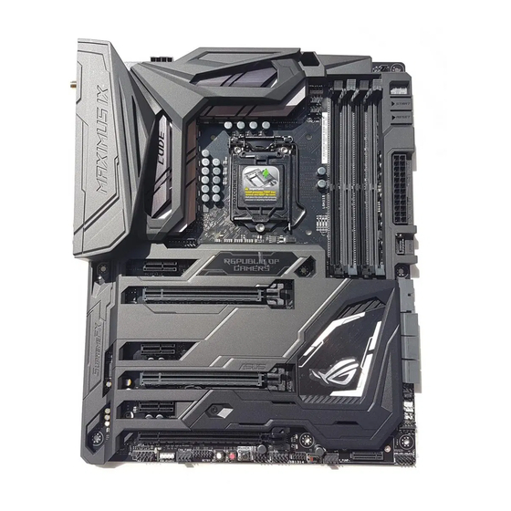
Page 18: Motherboard Layout
1.1.2 Motherboard layout 1.1.9 Internal connectors 2.3.1 Rear I/O connection Chapter 1: Product Introduction... - Page 19 Layout contents Connectors/Jumpers/Buttons and switches/Slots Page 1-26 1-29 1-22 1-22 ® 1-21 1-20 1-31 1-27 1-30 1-12 1-23 1-10 1-11 1-11 1-31 ASUS MAXIMUS IX CODE...
-
Page 20: Central Processing Unit (Cpu)
1.1.3 Central Processing Unit (CPU) ® Chapter 1: Product Introduction... -
Page 21: System Memory
1.1.4 System memory Recommended memory configurations ASUS MAXIMUS IX CODE... - Page 22 Memory configurations ® Chapter 1: Product Introduction...
-
Page 23: Expansion Slots
1.1.5 Expansion slots Slot No. Slot Description ASUS MAXIMUS IX CODE... - Page 24 IRQ assignments for this motherboard PCIe operating mode VGA Configuration PCIe_x16/x8_1 PCIe_x8_2 PCIe operating mode PCIe Lane Auto mode x4 mode ® Chapter 1: Product Introduction...
-
Page 25: Onboard Buttons And Switches
1.1.6 Onboard buttons and switches Power-on button (START) RESET button (RESET) ASUS MAXIMUS IX CODE... - Page 26 MemOK! button (MemOK!) 1.1.7 Onboard LEDs ® Chapter 1: Product Introduction 1-10...
- Page 27 Safe Boot button (SAFE_BOOT) ReTry button (RETRY_BUTTON) ASUS MAXIMUS IX CODE 1-11...
- Page 28 Slow Mode Switch (SLOW_MODE) Chapter 1: Product Introduction 1-12...
-
Page 29: Onboard Leds
1.1.7 Onboard LEDs Q LEDs (BOOT_DEVICE_LED, VGA_LED, DRAM_LED, CPU_LED) Button LEDs (BTN_LED1-2) ASUS MAXIMUS IX CODE 1-13... - Page 30 Q-Code LED Chapter 1: Product Introduction...
- Page 31 Q-Code table Code Description 0C – 0D 11 – 14 15 – 18 19 – 1C 2B – 2F 32 – 36 37 – 3A 3B – 3E 50 – 53 ASUS MAXIMUS IX CODE...
- Page 32 Q-Code table Code Description 5C – 5F E4 – E7 EC – EF F5 – F7 FB – FF 63 – 67 6B – 6F Chapter 1: Product Introduction 1-16...
- Page 33 Q-Code table Code Description 73 – 77 7A – 7F 9E – 9F ASUS MAXIMUS IX CODE 1-17...
- Page 34 Q-Code table Code Description B8– BF Chapter 1: Product Introduction...
- Page 35 ACPI/ASL Checkpoints Code Description 0x01 0x02 0x03 0x04 0x05 0x10 0x20 0x30 0x40 0xAC 0xAA ASUS MAXIMUS IX CODE 1-19...
-
Page 36: Jumper
1.1.8 Jumper LN2 Mode jumper (3-pin LN2_MODE) Chapter 1: Product Introduction 1-20... -
Page 37: Internal Connectors
1.1.9 Internal connectors Intel ® Z270 Serial ATA 6 Gb/s connectors (7-pin SATA6G_12; SATA6G_34; SATA6G_56) ® ® AHCI Intel RST Premium With Intel Optane System Acceleration (RAID) RAID configurations AHCI ASUS MAXIMUS IX CODE 1-21... - Page 38 USB 3.1 front panel connector (USB3.1_E1) USB 3.0 connector (20-1 pin USB3_12) Chapter 1: Product Introduction 1-22...
- Page 39 USB 2.0 connector (10-1 pin USB1314) ASUS MAXIMUS IX CODE 1-23...
- Page 40 Front panel audio connector (10-1 pin AAFP) LED connectors (5-pin RGB_LED_STRIP1; RGB_LED_STRIP2) Chapter 1: Product Introduction...
- Page 41 CPU, CPU optional, high amp, extension, water pump+, AIO pump, and chassis fan connectors (4-pin CPU_FAN; 4-pin CPU_OPT; 4-pin H_AMP; 5-pin EXT_FAN; 4-pin W_PUMP+; 4-pin AIO_PUMP; 4-pin CHA_FAN1-3) Header Max. Current Max. Power Default Speed Shared Control ASUS MAXIMUS IX CODE...
- Page 42 ATX power connectors (24-pin EATXPWR; 8-pin EATX12V) Chapter 1: Product Introduction 1-26...
- Page 43 System panel connectors (10-1 pin F_PANEL; 4-pin SPEAKER) ASUS MAXIMUS IX CODE 1-27...
- Page 44 ROG extension connector (18-1 pin ROG_EXT) Thermal sensor connector (2-pin T_SENSOR) Chapter 1: Product Introduction...
- Page 45 AURA RGB headers (4-pin RGB_HEADER1-2) ASUS MAXIMUS IX CODE 1-29...
- Page 46 M.2 sockets (M.2_1; M.2_2) ® ® ® Chapter 1: Product Introduction 1-30...
- Page 47 TPM connector (14-1 pin TPM) Water in, water out, and water flow connectors (2-pin W_IN; 2-pin W_OUT; 3-pin W_FLOW) ASUS MAXIMUS IX CODE 1-31...
- Page 48 Chapter 1: Product Introduction 1-32...
-
Page 49: Chapter 2: Basic Installation
2.1.1 Motherboard installation Install the ASUS Q-Shield to the chassis rear I/O panel. Place the motherboard into the chassis, ensuring that its rear I/O ports are aligned to the chassis’ rear I/O panel. - Page 50 Place nine (9) screws into the holes indicated by circles to secure the motherboard to the chassis. DO NOT over tighten the screws! Doing so can damage the motherboard. Chapter 2: Basic Installation...
-
Page 51: Cpu Installation
Ensure that you install the correct CPU designed for LGA1151 socket only. DO NOT install a CPU designed for LGA1155 and LGA1156 sockets on the LGA1151 socket. Top of CPU Bottom of CPU Bottom of CPU ASUS MAXIMUS IX CODE... - Page 52 Top of CPU ® LGA1151 socket. on the motherboard. the CPU Installation Tool. picking up the CPU Installation Tool. Tool to prevent CPU damage. incorrect CPU orientation/placement, or other damages resulting from negligence by the user. Chapter 2: Basic Installation...
-
Page 53: Cpu Heatsink And Fan Assembly Installation
2.1.3 CPU heatsink and fan assembly installation Apply the Thermal Interface Material to the CPU heatsink and CPU before you install the heatsink and fan, if necessary. To install the CPU heatsink and fan assembly ASUS MAXIMUS IX CODE... - Page 54 To uninstall the CPU heatsink and fan assembly Chapter 2: Basic Installation...
-
Page 55: Dimm Installation
2.1.4 DIMM installation To remove a DIMM ASUS MAXIMUS IX CODE... -
Page 56: Atx Power Connection
2.1.5 ATX power connection Ensure to connect the 8-pin power plug. 2.1.6 SATA device connection Chapter 2: Basic Installation... -
Page 57: Front I/O Connector
USB 3.1 orientation. Push the connector until it clicks into place. To install USB 3.0 connector To install USB 2.0 connector USB 3.0 USB 2.0 To install front panel audio connector To install system speaker connector AAFP ASUS MAXIMUS IX CODE... -
Page 58: Expansion Card Installation
2.1.8 Expansion card installation To install PCIe x16 cards To install PCIe x1 cards 2-10 Chapter 2: Basic Installation... -
Page 59: M.2 Installation
2.1.9 M.2 installation Supported M.2 type varies per motherboard. ASUS MAXIMUS IX CODE 2-11... -
Page 60: Wi-Fi Antenna Installation
2.1.10 Wi-Fi antenna installation Installing the ASUS 2x2 dual band W-Fi antenna Connect the bundled ASUS 2x2 dual band Wi-Fi antenna connector to the Wi-Fi ports at the back of the chassis. IO Shield ports. The illustration above is for reference only. The I/O port layout may vary with models, but the Wi-Fi antenna installation procedure is the same for all models. -
Page 61: Bios Update Utility
Updating BIOS in Chapter 3. Updating BIOS may have risks. If the BIOS program is damaged during the process and results to the system’s failure to boot up, please contact your local ASUS Service Center. ASUS MAXIMUS IX CODE 2-13... -
Page 62: Motherboard Rear And Audio Connections
Motherboard rear and audio connections 2.3.1 Rear I/O connection Rear panel connectors Clear CMOS button (CLR_CMOS). Press this button to clear the BIOS setup information only when the systems hangs due to overclocking. DisplayPort ® Intel USB 2.0 ports 7, 8, 9, and 10 ®... -
Page 63: Audio I/O Connections
Front Speaker Out Front Speaker Out Pink Mic In Mic In Mic In Mic In Center/Sub Center/Sub Orange – – woofer woofer Black – Rear Speaker Out Rear Speaker Out Rear Speaker Out 2.3.2 Audio I/O connections Audio I/O ports ASUS MAXIMUS IX CODE 2-15... - Page 64 Connect to Headphone and Mic Connect to Stereo Speakers Connect to 2 channel Speakers 2-16 Chapter 2: Basic Installation...
- Page 65 Connect to 4 channel Speakers Connect to 6 channel Speakers Connect to 8 channel Speakers ASUS MAXIMUS IX CODE 2-17...
-
Page 66: Starting Up For The First Time
Starting up for the first time After making all the connections, replace the system case cover. Ensure that all switches are off. Connect the power cord to the power connector at the back of the system chassis. Connect the power cord to a power outlet that is equipped with a surge protector. Turn on the devices in the following order: Monitor External SCSI devices (starting with the last device on the chain) -
Page 67: Chapter 3: Bios Setup
Chapter 3: BIOS Setup BIOS Setup Knowing BIOS DO NOT change the default BIOS settings We strongly recommend that you change the BIOS settings only with the help of a trained service personnel M9C.CAP ASUS MAXIMUS IX CODE... -
Page 68: Bios Setup Program
BIOS setup program Entering BIOS at startup Entering BIOS Setup after POST Load Optimized Defaults Exit <F5> 3.10 Exit Menu 1.1.6 Onboard buttons and switches BIOS menu screen EZ Mode Advanced Mode Setup Mode in Boot menu Chapter 3: BIOS Setup... -
Page 69: Ez Mode
Displays the CPU Fan’s speed. Click the button to manually tune the fans Click to go to Advanced mode Loads optimized Search on the FAQ default settings Click to display boot devices Selects the boot device priority ASUS MAXIMUS IX CODE... -
Page 70: Advanced Mode
3.2.2 Advanced Mode Advanced Mode(F7) Configuration fields Pop-up Menu Scroll bar Menu bar Language MyFavorite(F3) Qfan Control(F6) EZ Tuning Wizard(F11) Hot Keys Go back to EZ Mode Last modified settings Menu items General help Search on the FAQ Displays the CPU temperature, CPU, and memory voltage output Chapter 3: BIOS Setup... - Page 71 Menu bar My Favorites Main Extreme Tweaker Advanced Monitor Boot Tool Exit Menu items Main Submenu items Language My Favorites(F3) 3.3 My Favorites Q-Fan Control(F6) 3.2.3 QFan Control EZ Tuning Wizard(F11) 3.2.4 EZ Tuning Wizard ASUS MAXIMUS IX CODE...
- Page 72 Search on FAQ Hot keys Scroll bar General help Configuration fields Last Modified button Chapter 3: BIOS Setup...
-
Page 73: Qfan Control
Click to activate DC Mode configured PWM Mode Select a profile to Click to apply the fan setting apply to your fans Click to undo the Click to go back to main menu changes Select to manually configure your fans ASUS MAXIMUS IX CODE... - Page 74 Configuring fans manually Manual Speed points Select to manually configure your fans Apply Exit (ESC) Chapter 3: BIOS Setup...
- Page 75 3.2.4 EZ Tuning Wizard OC setup RAID setup OC Tuning Next Daily Computing Gaming/Media Editing, Next ASUS MAXIMUS IX CODE...
- Page 76 BOX cooler, Tower cooler, Water cooler, I’m not sure, Next Next Creating RAID RAID Next ® PCIE SATA Next Chapter 3: BIOS Setup 3-10...
- Page 77 Easy Backup Super Speed Next Next Easy Backup (RAID1) Easy Backup (RAID10) Next Super Speed (RAID0) Super Speed (RAID5) Next ASUS MAXIMUS IX CODE 3-11...
-
Page 78: My Favorites
My Favorites Chapter 3: BIOS Setup 3-12... - Page 79 Adding items to My Favorites Main menu panel Selected shortcut items Submenu panel Delete all favorite items Recover to default favorite items Exit (ESC) ASUS MAXIMUS IX CODE 3-13...
-
Page 80: Main Menu
Main menu Security 1.1.6 Onboard buttons and switches [Not Installed] [Installed] Extreme Tweaker menu Ai Overclock Tuner Chapter 3: BIOS Setup 3-14... - Page 81 [Manual] BCLK Frequency ASUS MultiCore Enhancement CPU Core Ratio BCLK Frequency : DRAM Frequency Ratio DRAM Frequency [TPU II]. ASUS MAXIMUS IX CODE 3-15...
-
Page 82: Advanced Menu
Internal CPU Power Management Intel(R) SpeedStep(tm) Turbo Mode Advanced menu 3.6.1 CPU Configuration Hyper-threading CPU Power Management Configuration Intel(R) SpeedStep(tm) Turbo Mode CPU C-States Chapter 3: BIOS Setup 3-16... - Page 83 3.6.2 Platform Misc Configuration 3.6.3 System Agent (SA) Configuration 3.6.4 PCH Configuration PCI Express Configuration PCIe Speed 3.6.5 PCH Storage Configuration Not Present SATA Controller(s) SATA Mode Selection S.M.A.R.T. Status Check ASUS MAXIMUS IX CODE...
-
Page 84: Rog Effects
SATA6G_1(Gray) - SATA6G_6(Gray) SATA6G_1(Gray) - SATA6G_6(Gray) Hot Plug AHCI 3.6.6 PCH-FW Configuration 3.6.7 ROG Effects Onboard LED Q-Code LED Function 3.6.8 Onboard Devices Configuration HD Audio Controller M.2_1 Configuration: [Auto][SATA mode][PCIE mode] M.2_2 PCIe Bandwidth Configuration: [X2][X4] Chapter 3: BIOS Setup 3-18... -
Page 85: Hdd/Ssd Smart Information
RGB LED lighting Intel LAN Controller 3.6.9 APM Configuration ErP Ready [Disabled] [Enabled] 3.6.10 Network Stack Configuration 3.6.11 HDD/SSD SMART Information 3.6.12 USB Configuration The Mass Storage Devices None USB Single Port Control 1.1.2 Motherboard layout ASUS MAXIMUS IX CODE 3-19... -
Page 86: Monitor Menu
Monitor menu Qfan Configuration Qfan Tuning AIO PUMP/W_PUMP+ Control Boot menu Fast Boot [Enabled] Next Boot after AC Power Loss Setup Mode Chapter 3: BIOS Setup 3-20... - Page 87 CSM (Compatibility Support Module) Launch CSM ® ® [Enabled] Boot Devices Control Boot from Network Devices Boot from Storage Devices Boot from PCI-E/PCI Expansion Devices Secure Boot ® ASUS MAXIMUS IX CODE 3-21...
-
Page 88: Tool Menu
® ® Boot Override Tool menu Setup Animator 3.9.1 ASUS EZ Flash 3 Utility 3.11.2 ASUS EZ Flash 3 3.9.2 Secure Erase Advanced > PCH Storage Configuration > SATA Mode Selection > AHCI. Tool > Secure Erase Chapter 3: BIOS Setup... - Page 89 1.1.2 Motherboard layout Displays the available SSDs Status definition: Frozen. Locked. ASUS MAXIMUS IX CODE 3-23...
-
Page 90: Asus Spd Information
3.9.3 ASUS Overclocking Profile Load Profile Profile Name Save to Profile Load/Save Profile from/to USB Drive 3.9.4 ROG OC Panel H-Key Configure Load Default Save Above Settings Load from profile 3.9.5 ASUS SPD Information Chapter 3: BIOS Setup 3-24... -
Page 91: Graphics Card Information
3.9.6 Graphics Card Information GPU Post Bus Interface 3.10 Exit menu Load Optimized Defaults Save Changes & Reset Discard Changes and Exit Launch EFI Shell from USB drives ASUS MAXIMUS IX CODE 3-25... -
Page 92: Updating Bios
3.11 Updating BIOS ® 3.11.1 EZ Update ® Chapter 3: BIOS Setup 3-26... -
Page 93: Asus Ez Flash 3
3.11.2 ASUS EZ Flash 3 To update the BIOS by USB: ASUS EZ Flash Utility by USB. ASUS MAXIMUS IX CODE... - Page 94 3.10 Exit Menu To update the BIOS by Internet: ASUS EZ Flash Utility by Internet. 3.10 Exit Menu Chapter 3: BIOS Setup 3-28...
-
Page 95: Asus Crashfree Bios 3
3.11.3 ASUS CrashFree BIOS 3 Recovering the BIOS To recover the BIOS: ASUS MAXIMUS IX CODE 3-29... - Page 96 Chapter 3: BIOS Setup 3-30...
-
Page 97: Chapter 4: Raid Support
RAID 1 (Data mirroring) copies and maintains an identical image of data from one drive to RAID 5 RAID 10 is data striping and data mirroring combined without parity (redundancy data) having ASUS MAXIMUS IX CODE... -
Page 98: Installing Serial Ata Hard Disks
4.1.2 Installing Serial ATA hard disks To install the SATA hard disks for a RAID configuration: 4.1.3 Intel ® Rapid Storage Technology in UEFI BIOS ® To enter the Intel Advanced menu > PCH Storage Configuration [Intel RST Premium With Intel Optane System Acceleration (RAID)] Boot menu >... - Page 99 Creating a RAID set ® Rapid Storage Technology menu, select Create RAID Volume and X for the disks you want to include in the ASUS MAXIMUS IX CODE...
- Page 100 We recommend a lower strip size for server systems, and a higher strip size for multimedia Capacity (MB) item is selected, enter the RAID volume capacity that you Create Volume and return to the Intel ® Chapter 4: RAID Support...
- Page 101 Deleting a RAID set ® Rapid Storage Technology menu, select the RAID volume you want to Delete Yes to delete the RAID ® Rapid Storage Technology menu, or select No to volume and return to the Intel ASUS MAXIMUS IX CODE...
-
Page 102: Intel ® Rapid Storage Technology Option Rom Utility
® 4.1.4 Intel Rapid Storage Technology Option ROM utility To enter the Intel ® Rapid Storage Technology Option ROM utility: RAID Volumes: None defined. Physical Devices: Port Device Model Serial # Size Type/Status(Vol ID) ST3160812AS 9LS0HJA4 149.0GB Non-RAID Disk ST3160812AS 9LS0F4HL 149.0GB Non-RAID Disk... - Page 103 Serial # Size Status ST3160812AS 9LS0HJA4 149.0GB Non-RAID Disk ST3160812AS 9LS0F4HL 149.0GB Non-RAID Disk ST3160812AS 3LS0JYL8 149.0GB Non-RAID Disk ST3160812AS 9LS0BJ5H 149.0GB Non-RAID Disk Select 2 to 6 to use in creating the volume. ]-Prev/Next [SPACE]-SelectDisk [ENTER]-Done ASUS MAXIMUS IX CODE...
- Page 104 We recommend a lower strip size for server systems, and a higher strip size for multimedia Capacity item is selected, enter the RAID volume capacity that you want Create Volume WARNING: ALL DATA ON SELECTED DISKS WILL BE LOST. Are you sure you want to create this volume? (Y/N) Chapter 4: RAID Support...
- Page 105 (This does not apply to Recovery volumes) ]-Select [ESC]-Previous Menu [DEL]-Delete Volume [DELETE VOLUME VERIFICATION] ALL DATA IN THE VOLUME WILL BE LOST! (This does not apply to Recovery volumes) Are you sure you want to delete “Volume0”? (Y/N): ASUS MAXIMUS IX CODE...
-
Page 106: Creating A Raid Driver Disk
® Exiting the Intel Rapid Storage Technology Option ROM utility To exit the utility: 5. Exit [CONFIRM EXIT] Are you sure you want to exit? (Y/N): Creating a RAID driver disk 4.2.1 Creating a RAID driver disk in Windows ® To install the RAID driver for Windows ®... -
Page 107: Appendix
Consult the dealer or an experienced radio/TV technician for help. The use of shielded cables for connection of the monitor to the graphics card is required expressly approved by the party responsible for compliance could void the user’s authority to operate this equipment. ASUS MAXIMUS IX CODE... - Page 108 IC: Canadian Compliance Statement 210 of Industry Canada. This Class B device meets all the requirements of the Canadian interference-causing equipment regulations. This device complies with Industry Canada license exempt RSS standard(s). Operation is subject to the following two conditions: (1) this device may not cause interference, and (2) this device must accept any interference, including interference that may cause undesired operation of the device.
- Page 109 ASUS Recycling/Takeback Services ASUS recycling and takeback programs come from our commitment to the highest standards for protecting our environment. We believe in providing solutions for you to be able to responsibly recycle our products, batteries, other components as well as the packaging materials.
- Page 110 FCC Bluetooth Wireless Compliance The antenna used with this transmitter must not be co-located or operated in conjunction with Bluetooth Industry Canada Statement This Class B device meets all requirements of the Canadian interference-causing equipment regulations. Cet appareil numérique de la Class B respecte toutes les exigences du Règlement sur le matériel brouilleur du Canada.
- Page 111 1999/5/ EZ. Cijeli tekst EU izjave o sukladnosti dostupan je na: www.asus.com/support Toto zariadenie môže byť prevádzkované v dolu uvedených krajinách: Ovaj uređaj može se koristiti u dolje navedenim zemljama: Slovenščina ASUSTeK Computer Inc.
-
Page 112: Asus Contact Information
800 Corporate Way, Fremont, CA 94539, USA Telephone +1-510-739-3777 +1-510-608-4555 Web site http://www.asus.com/us/ Technical Support Support fax +1-812-284-0883 Telephone +1-812-282-2787 Online support http://qr.asus.com/techserv ASUS COMPUTER GmbH (Germany and Austria) +49-2102-959931 Web site http://www.asus.com/de Online contact http://eu-rma.asus.com/sales Technical Support Telephone +49-2102-5789555 Support Fax +49-2102-959911 Online support http://qr.asus.com/techserv... - Page 113 800 Corporate Way, Fremont Phone/Fax No: (510)739-3777/(510)608-4555 hereby declares that the product Product Name : Motherboard Model Number : MAXIMUS IX CODE Conforms to the following specifications: FCC Part 15, Subpart B, Unintentional Radiators Supplementary Information: This device complies with part 15 of the FCC Rules. Operation is subject to the...
- Page 114 Appendix...