Asus MAXIMUSII/FORMULA - Maximus II Formula Motherboard User Manual
User manual
Hide thumbs
Also See for MAXIMUSII/FORMULA - Maximus II Formula Motherboard:
- User manual (8 pages) ,
- User manual (44 pages)
Table of Contents
Advertisement
Advertisement
Table of Contents

Related Manuals for Asus MAXIMUSII/FORMULA - Maximus II Formula Motherboard


Summary of Contents for Asus MAXIMUSII/FORMULA - Maximus II Formula Motherboard
- Page 1 Maximus II Formula...
- Page 2 Product warranty or service will not be extended if: (1) the product is repaired, modified or altered, unless such repair, modification of alteration is authorized in writing by ASUS; or (2) the serial number of the product is defaced or missing.
-
Page 3: Table Of Contents
Product highlights ............1-2 1.3.2 ROG Intelligent Performance & Overclocking features ... 1-4 1.3.3 ROG unique features ............1-6 1.3.4 ASUS special features ............ 1-7 Chapter 2: Hardware information Before you proceed ..............2-1 Motherboard overview ..............2-4 2.2.1 Motherboard layout ............2-4 2.2.2... -
Page 4: Contents
BIOS setup Managing and updating your BIOS ..........3-1 3.1.1 ASUS Update utility ............3-1 3.1.2 ASUS EZ Flash 2 utility ........... 3-4 3.1.3 AFUDOS utility ..............3-5 3.1.4 ASUS CrashFree BIOS 3 utility ........3-7 BIOS setup program ..............3-8 3.2.1... - Page 5 Boot Settings Configuration .......... 3-39 3.7.3 BIOS Boot Priority ............3-40 3.7.4 Security ................. 3-41 Tools menu ................. 3-43 3.8.1 ASUS EZ Flash 2 ............3-43 3.8.2 ASUS O.C. Profile ............3-44 3.8.3 BIOS Flashback ............3-45 Exit menu ..................3-46...
- Page 6 ASUS MyLogo3™ ............4-9 4.3.2 AI NET 2.................4-11 4.3.3 Sound Blaster X-Fi audio utility ........4-12 4.3.4 ASUS PC Probe II ............4-16 4.3.5 ASUS EPU-Six Engine ..........4-22 4.3.6 ASUS AI Suite ............... 4-26 4.3.7 ASUS AI Nap ..............4-28 4.3.8...
- Page 7 Contents Intel Hyper-Threading Technology ...........A-3 ® Using the Hyper-Threading Technology ........A-3 Debug code table .................A-4...
-
Page 8: Notices
Notices Federal Communications Commission Statement This device complies with Part 15 of the FCC Rules. Operation is subject to the following two conditions: • This device may not cause harmful interference, and • This device must accept any interference received including interference that may cause undesired operation. -
Page 9: Safety Information
Safety information Electrical safety • To prevent electrical shock hazard, disconnect the power cable from the electrical outlet before relocating the system. • When adding or removing devices to or from the system, ensure that the power cables for the devices are unplugged before the signal cables are connected. -
Page 10: About This Guide
Refer to the following sources for additional information and for product and software updates. ASUS websites The ASUS website provides updated information on ASUS hardware and software products. Refer to the ASUS contact information. Optional documentation Your product package may include optional documentation, such as warranty flyers, that may have been added by your dealer. -
Page 11: Conventions Used In This Guide
Conventions used in this guide To make sure that you perform certain tasks properly, take note of the following symbols used throughout this manual. DANGER/WARNING: Information to prevent injury to yourself when trying to complete a task. CAUTION: Information to prevent damage to the components when trying to complete a task. -
Page 12: Maximus Ii Formula Specifications Summary
™ ® ® core / Celeron processors ® Intel EM64T / EIST / Hyper-Threading Technology ® * Refer to www.asus.com for Intel CPU support list Chipset Intel P45 / ICH10R with Intel Fast Memory Access ® ® Technology System Bus... - Page 13 - AI Overclocking (intelligent CPU frequency tuner) - AI Booster Utility - O.C. Profile Overclocking protection: - COP EX (Component Overheat Protection -EX) - Voltiminder LED - ASUS C.P.R. (CPU Parameter Recall) ROG Special Features Speeding HDD Pin-Fin Thermal Module BIOS Flashback LCD Poster...
- Page 14 WOL by PME, WOR by PME, Chassis Intrusion, PXE Accessories SupremeFX X-Fi Audio Card LCD Poster ASUS Optional Fan 3 in 1 ASUS Q-connector kit UltraDMA 133/100/66 cable Floppy disk drive cable Serial ATA cables Serial ATA power cables 2-port USB2.0 + IEEE 1394a module...
-
Page 15: Chapter 1: Product Introduction
This chapter describes the motherboard features and the new technologies it supports. Chapter 1: Product introduction... - Page 16 Chapter summary Welcome! ..................1-1 Package contents ................. 1-1 Special features ................1-2 ASUS Maximus II Formula...
-
Page 17: Welcome
® The motherboard delivers a host of new features and latest technologies, making it another standout in the long line of ASUS quality motherboards! Before you start installing the motherboard, and hardware devices on it, check the items in your package with the list below. -
Page 18: Special Features
Dual-channel DDR2 memory support To attain top performance, ASUS engineers have successfully unleashed the true potential of DDR2 memory. While in DDR2 1200 mode, ASUS’s exclusive technology offers a choice of FSB 1600, providing great performance for 3D graphics and other memory demanding applications. -
Page 19: High Definition Audio
192KHz/24-bit audio output, jack-sensing feature, retasking functions, and multi- streaming technology that simultaneously sends different audio streams to different destinations. You can now talk to your partners on the headphones while playing multi-channel network games. See pages 2-21 for details. ASUS Maximus II Formula... -
Page 20: Rog Intelligent Performance & Overclocking Features
Green ASUS This motherboard and its packaging comply with the European Union’s Restriction on the use of Hazardous Substances (RoHS). This is in line with the ASUS vision of creating environment-friendly and recyclable products/packaging to safeguard consumers’ health while minimizing the impact on the environment. -
Page 21: Bios Flashback
The COP EX allows overclockers to increase chipset voltages without the worries of overheating. It can also be used to monitor and save an overheating GPU. The COP EX allows more freedom and less constraint for maximum performance achievement. ASUS Maximus II Formula... -
Page 22: Rog Unique Features
AI Booster The ASUS AI Booster allows you to overclock the CPU speed in Windows ® environment without the hassle of booting the BIOS. See page 4-31 for details. C.P.R. (CPU Parameter Recall) When the system hangs due to overclocking failure, there is no need to open the system chassis to clear CMOS data. -
Page 23: Asus Special Features
Fanless Design—Stack Cool 2 ASUS Stack Cool 2 is a fan-less and zero-noise cooling solution that lowers the temperature of critical heat generating components. The motherboard uses a special design on the printed circuit board (PCB) to dissipate heat these critical components generate. -
Page 24: Asus Mylogo 3
See page 2-36 for details. ASUS MyLogo 3 ASUS MyLogo 3 is a new feature present in the motherboard that allows you to personalize and add style to your system with customizable and animated boot logos. -
Page 25: Chapter 2: Hardware Information
This chapter lists the hardware setup procedures that you have to perform when installing system components. It includes description of the jumpers and connectors on the motherboard. Chapter 2: Hardware information... - Page 26 Central Processing Unit (CPU) ........... 2-7 System memory ................. 2-13 Expansion slots ................2-16 Jumpers ..................2-19 Connectors Connectors ................2-21 Installing accessories ..............2-36 Starting up for the first time ............2-39 2.10 Turning off the computer ............2-40 ASUS Maximus II Formula...
-
Page 27: Before You Proceed
BIOS. Refer to the illustration below for the location of the CPU LED and the table below for LED definition. Normal (green) High (yellow) Crazy (red) CPU Voltage 0.85000–1.50000 1.50625–1.69375 1.70000– CPU PLL Voltage 1.50000–1.61925 1.63250–1.81800 1.83125– ASUS Maximus II Formula... - Page 28 Memory LED Refer to the illustration below for the location of the memory LED and the table below for LED definition. Normal (green) High (yellow) Crazy (red) DRAM Voltage 1.80000–1.99875 2.01200–2.60825 2.62150– Northbridge/Southbridge LEDs The northbridge and southbridge LEDs each have two different voltage displays.
- Page 29 When you turn on the ATX power supply, the Power LED flashes three times to indicate that the system is ready to boot. Wait till the flash stops before you press the power-on switch. ASUS Maximus II Formula...
-
Page 30: Motherboard Overview
Motherboard overview 2.2.1 Motherboard layout 2.2.2 SupremeFX-Fi audio card layout Refer to pages 2-21 and 2-30 for details UPREME about the audio jacks and connectors Listen with Absolutely HD on this card. Chapter 2: Hardware information... -
Page 31: Layout Contents
Reset switch 2-35 Thermal sensor cable connectors (2-pin OPT_TEMP1–3) 2-29 IEEE 1394a port connector (10-1 pin IE1394_2) 2-27 ROG connector (2-pin ROG) 2-32 Refer to 2.7 Connectors for more information about rear panel connectors and internal connectors. ASUS Maximus II Formula... -
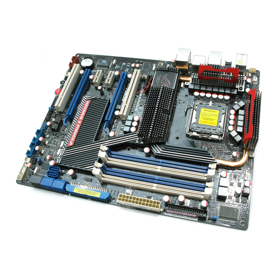
Page 32: Placement Direction
2.2.4 Placement direction When installing the motherboard, make sure that you place it into the chassis in the correct orientation. The edge with external ports goes to the rear part of the chassis as indicated in the image below. 2.2.5 Screw holes Place nine (9) screws into the holes indicated by circles to secure the motherboard to the chassis. -
Page 33: Central Processing Unit (Cpu)
ASUS will shoulder the cost of repair only if the damage is shipment/transit-related. • Keep the cap after installing the motherboard. ASUS will process Return Merchandise Authorization (RMA) requests only if the motherboard comes with the cap on the LGA775 socket. -
Page 34: Installing The Cpu
2.3.1 Installing the CPU To install a CPU: Locate the CPU socket on the motherboard. Before installing the CPU, make sure that the cam box is facing towards you and the load lever is on your left. Press the load lever with your thumb Retention tab (A), then move it to the left (B) until it is released from the retention tab. - Page 35 The Thermal Interface Material is toxic and inedible. If it gets into your eyes or touches your skin, ensure to wash it off immediately, and seek professional medical help. To prevent contaminating the paste, DO NOT spread the paste with your finger directly. ASUS Maximus II Formula...
- Page 36 Close the load plate (A), then push the load lever (B) until it snaps into the retention tab. The motherboard supports Intel ® LGA775 processors with the Intel ® Enhanced Memory 64 Technology (EM64T), Enhanced Intel SpeedStep Technology ® (EIST), and Hyper-Threading Technology. Refer to the Appendix for more information on these CPU features.
-
Page 37: Installing The Cpu Heatsink And Fan
Push down two fasteners at a time in a diagonal sequence to secure the heatsink and fan assembly in place. Orient the heatsink and fan assembly such that the CPU fan cable is closest to the CPU fan connector. ASUS Maximus II Formula 2-11... -
Page 38: Uninstalling The Cpu Heatsink And Fan
Connect the CPU fan cable to the connector on the motherboard labeled CPU_FAN. DO NOT forget to connect the CPU fan connector! Hardware monitoring errors can occur if you fail to plug this connector. 2.3.3 Uninstalling the CPU heatsink and fan To uninstall the CPU heatsink and fan: Disconnect the CPU fan cable from the connector on the motherboard. -
Page 39: System Memory
240-pin footprint compared to the 184-pin DDR DIMM. DDR2 DIMMs are notched differently to prevent installation on a DDR DIMM socket. The figure illustrates the location of the DDR2 DIMM sockets: Channel Sockets Channel A DIMM_A1 and DIMM_A2 Channel B DIMM_B1 and DIMM_B2 ASUS Maximus II Formula 2-13... -
Page 40: Memory Configurations
2.4.2 Memory configurations You may install 512 MB, 1 GB, 2 GB and 4GB unbuffered and non-ECC DDR2 DIMMs into the DIMM sockets. • You may install varying memory sizes in Channel A and Channel B. The system maps the total size of the lower-sized channel for the dual-channel configuration. -
Page 41: Installing A Dimm
Simultaneously press the retaining clips outward to unlock the DIMM. DDR2 DIMM notch Support the DIMM lightly with your fingers when pressing the retaining clips. The DIMM might get damaged when it flips out with extra force. ASUS Maximus II Formula 2-15... -
Page 42: Expansion Slots
Expansion slots In the future, you may need to install expansion cards. The following sub-sections describe the slots and the expansion cards that they support. Make sure to unplug the power cord before adding or removing expansion cards. Failure to do so may cause you physical injury and damage motherboard components. -
Page 43: Interrupt Assignments
– – – – – SATA controller 2 – – – shared – – – – Audio Azalia – – – – – – shared – IEEE 1394 shared – – – – – – ASUS Maximus II Formula 2-17... -
Page 44: Pci Slots
2.5.4 PCI slots The PCI slots support cards such as a LAN card, SCSI card, USB card, and other cards that comply with PCI specifications. Refer to the figure below for the location of the slots. 2.5.5 PCI Express x1 slots This motherboard supports PCI Express x1 network cards, SCSI cards and other cards that comply with the PCI Express specifications. -
Page 45: Jumpers
If the system hangs due to overclocking of memory timing or chipset voltage and the power button fails to function, pressing down the clr CMOS switch will shut down the system and clear CMOS simultaneously. ASUS Maximus II Formula 2-19... - Page 46 BIOS flash setting (6-pin BIOS_FLASHBACK) Two sets of BIOS Flash ROM (BIOS 1 and BIOS 2) are present on this motherboard. This jumper allows you to select either BIOS as the one to boot, or back up or restore BIOS content from one ROM to the other. Moving the jumper cap to pins 1-2 (default) allows you to enter BIOS MENU to select which BIOS to boot.
-
Page 47: Connectors
LED indications. LAN port LED indications Activity/Link Speed LED Description ACTIVITY/ SPEED LINK LED Soft-off Mode YELLOW* During Power ON/OFF YELLOW* ORANGE 100 Mbps connection LAN port YELLOW* GREEN 1 Gbps connection * Blinking ASUS Maximus II Formula 2-21... - Page 48 Line In port (light blue). This port connects the tape, CD, DVD player, or other audio sources. Line Out port (lime). This port connects a headphone or a speaker. In 4-channel, 6-channel, and 8-channel configuration, the function of this port becomes Front Speaker Out.
-
Page 49: Internal Connectors
Pin 5 on the connector is removed to prevent incorrect cable connection when using a FDD cable with a covered Pin 5. ASUS Maximus II Formula 2-23... - Page 50 IDE connector (40-1 pin PRI_EIDE) The onboard IDE connector is for the Ultra DMA 133/100/66 signal cable. There are three connectors on each Ultra DMA 133/100/66 signal cable: blue, black, and gray. Connect the blue connector to the motherboard’s IDE connector, then select one of the following modes to configure your device.
- Page 51 Connect the right-angle side of SATA signal cable to SATA device. Or you may connect the right-angle side of SATA cable to the onboard SATA port to avoid mechanical conflict with huge graphics cards. ASUS Maximus II Formula 2-25...
- Page 52 SIL5723 Serial ATA RAID connectors (7-pin SPEEDING HDD1/2 [black]) These connectors are for the Serial ATA signal cables for Serial ATA hard disk drives. If you install SATA hard disk drives, you can create a Super Speed or an EZ Backup configuration with the Speeding HDD Technology through the onboard Silicon Image SIL5723 controller.
- Page 53 Never connect a 1394 cable to the USB connectors. Doing so will damage the motherboard! You can connect the USB cable to ASUS Q-Connector (USB, blue) first, and then install the Q-Connector (USB) to the USB connector onboard. IEEE 1394a port connector (10-1 pin IE1394_2) This connector is for a IEEE 1394a port.
- Page 54 DO NOT place jumper caps on the fan connectors! • Only the CPU_FAN, CHA_FAN1–3, and OPT_FAN1–3 connectors support the ASUS Fan Xpert feature. • If you install two VGA cards, we recommend that you plug the chassis fan cable to the motherboard connector labled OPT_FAN1/2/3 for better thermal environment.
- Page 55 By default, the pin labeled “Chassis Signal” and “Ground” are shorted with a jumper cap. Remove the jumper caps only when you intend to use the chassis intrusion detection feature. ASUS Maximus II Formula 2-29...
-
Page 56: Connectors
10. Audio connectors Optical drive audio connector: This connector allows you to receive stereo This connector allows you to receive stereo allows you to receive stereo audio input from sound sources such as a CD-ROM, TV tuner, or MPEG card. Front panel audio connector: This connector is for a chassis-mounted front panel audio I/O module that supports either HD Audio or legacy AC`97 audio standard. - Page 57 500W to 600W power or above to ensure the system stability. • If you are uncertain about the minimum power supply requirement for your system, refer to the Recommended Power Supply Wattage Calculator at http://support.asus.com/PowerSupplyCalculator/PSCalculator. aspx?SLanguage=en-us for details. ASUS Maximus II Formula 2-31...
- Page 58 12. ROG connector (2-pin ROG) This connector is for the box labeled as Republic of Gamers on the heatpipe assembly. Connect the cable of the box to this connector, and the box lights up when the system is on. 2-32 Chapter 2: Hardware information...
-
Page 59: System Panel Connector
BIOS settings. Pressing the power switch for more than four seconds while the system is ON turns the system OFF. • Reset button (2-pin RESET) This 2-pin connector is for the chassis-mounted reset button for system reboot without turning off the system power. ASUS Maximus II Formula 2-33... -
Page 60: Asus Q-Connector
ASUS Q-Connector (system panel) You can use the ASUS Q-Connector to connect/disconnect chassis front panel cables in a few steps. Refer to the instructions below to install the ASUS Q- Connector. Connect the front panel cables to the ASUS Q-Connector. -
Page 61: Onboard Switches
This is ideal for overclockers and gamers who continually change settings to enhance system performance. Power-on switch Press the power-on switch to wake/power up the system. Reset switch Press the reset switch to reboot the system. ASUS Maximus II Formula 2-35... -
Page 62: Installing Accessories
Installing accessories 2.8.1 Installing the optional fan Install the optional fan only if you are using a passive cooler or a water cooler. Installing the optional fan with an active CPU cooler will interfere with the airflow and destabilize the system. Fit the fan to the grooved edge of Position the fan above the pipe the heatsink. -
Page 63: Installing The Audio Card
Locate the audio slot on the package. motherboard. Align the card connector with the The photo below shows the slot and press firmly until the card audio card installed on the sits on the slot completely. motherboard. ASUS Maximus II Formula 2-37... -
Page 64: Installing Q-Shield And Lcd Poster
2.8.3 Installing Q-shield and LCD Poster Install the Q-shield to the chassis Orient the motherboard and install by snapping it in place from inside. it to the chassis. Make sure that the motherboard external ports fit the shield openings. Thread the LCD Poster cable Plug the LCD Poster cable into through the opening until its the onboard connector labeled... -
Page 65: Starting Up For The First Time
No VGA detected short beeps One continuous beep followed by four Hardware component failure short beeps At power on, hold down the <Delete> key to enter the BIOS Setup. Follow the instructions in Chapter 3. ASUS Maximus II Formula 2-39... -
Page 66: 2.10 Turning Off The Computer
2.10 Turning off the computer 2.10.1 Using the OS shut down function If you are using Windows Vista: ® Click the Start button and then select Shut Down. The power supply should turn off after Windows shuts down. ® If you are using Windows ®... -
Page 67: Chapter 3: Bios Setup
This chapter tells how to change the system settings through the BIOS Setup menus. Detailed descriptions of the BIOS parameters are also provided. BIOS setup... - Page 68 Managing and updating your BIOS ..........3-1 BIOS setup program ..............3-8 Extreme Tweaker menu ............. 3-11 Main menu .................. 3-20 Advanced menu ................. 3-25 Power menu ................3-33 Boot menu .................. 3-38 Tools menu ................. 3-43 Exit menu ..................3-46 ASUS Maximus II Formula...
-
Page 69: Managing And Updating Your Bios
ASUS Update (Updates the BIOS in Windows environment.) ® ASUS EZ Flash 2 (Updates the BIOS using a floppy disk or USB flash disk.) ASUS AFUDOS (Updates the BIOS using a bootable floppy disk) ASUS CrashFree BIOS 3 (Updates the BIOS using a bootable floppy disk, USB flash disk or the motherboard support DVD when the BIOS file fails or gets corrupted.) - Page 70 To update the BIOS through the Internet: desktop by clicking Start Launch the ASUS Update utility from the Windows ® > Programs > ASUS > ASUSUpdate > ASUSUpdate. The ASUS Update main window appears. Select Update BIOS from the Select the ASUS FTP site nearest...
- Page 71 To update the BIOS through a BIOS file: desktop by clicking Start Launch the ASUS Update utility from the Windows ® > Programs > ASUS > ASUSUpdate > ASUSUpdate. The ASUS Update main window appears. Select Update BIOS from a file option from the drop-down menu, then click Next.
-
Page 72: Asus Ez Flash 2 Utility
3.1.2 ASUS EZ Flash 2 utility The ASUS EZ Flash 2 feature allows you to update the BIOS without having to go through the long process of booting from a floppy disk and using a DOS-based utility. The EZ Flash 2 utility is built-in the BIOS chip so it is accessible by pressing <Alt>... -
Page 73: Afudos Utility
Updating the BIOS file To update the BIOS file using the AFUDOS utility: Visit the ASUS website (www.asus.com) and download the latest BIOS file for the motherboard. Save the BIOS file to a bootable floppy disk. ASUS Maximus II Formula... - Page 74 A:\>afudos /iFormula.ROM The utility verifies the file and starts updating the BIOS. A:\>afudos /iFormula.ROM AMI Firmware Update Utility - Version 1.19(ASUS V2.07(03.11.24BB)) Copyright (C) 2002 American Megatrends, Inc. All rights reserved. WARNING!! Do not turn off power during flash BIOS Reading file ..
-
Page 75: Asus Crashfree Bios 3 Utility
3.1.4 ASUS CrashFree BIOS 3 utility The ASUS CrashFree BIOS 3 is an auto recovery tool that allows you to restore the BIOS file when it fails or gets corrupted during the updating process. You can update a corrupted BIOS file using the motherboard support DVD, the floppy disk, or the USB flash disk that contains the updated BIOS file. -
Page 76: Bios Setup Program
The BIOS setup screens shown in this section are for reference purposes only, and may not exactly match what you see on your screen. • Visit the ASUS website (www.asus.com) to download the latest BIOS file for this motherboard. Chapter 3: BIOS setup... -
Page 77: Bios Menu Screen
At the bottom right corner of a menu screen are the navigation keys for that particular menu. Use the navigation keys to select items in the menu and change the settings. Some of the navigation keys differ from one screen to another. ASUS Maximus II Formula... -
Page 78: Menu Items
3.2.4 Menu items The highlighted item on the menu bar Use [ENTER], [TAB], System Time [06:22:54] or [SHIFT-TAB] to System Date [Thur 10/04/2007] displays the specific items for that select a field. Legacy Diskette A [1.44M, 3.5 in] Language [English] Use [+] or [-] to menu. -
Page 79: Extreme Tweaker Menu
DDR2 ChA Reference Voltage [Auto] DDR2 ChB Reference Voltage [Auto] North Bridge DDR Reference [Auto] NB GTL Reference [Auto] Load-Line Calibration [Auto] CPU Configuration Spread Spectrum [Auto] PCIE Spread spectrum [Auto] v02.61 (C)Copyright 1985-2008, American Megatrends, Inc. ASUS Maximus II Formula 3-11... -
Page 80: Configure System Performance Settings
3.3.1 Configure System Performance Settings CPU Level Up [Auto] Allows you to select a CPU level, and the related parameters will be automatically adjusted according to the selected CPU level. If you want to manually configure the settings in detail, set Ai Overclock Tuner to [Manual] after selecting a CPU level. Configuration options: [Auto] [E6400] [E6550] [E6600] [E6700] [X6800] [E6850] [Crazy] The configuration options may vary depending on your CPU model. - Page 81 CAS# Latency [5 DRAM Clocks] Configuration options: [3 DRAM Clocks] [4 DRAM Clocks]–[11 DRAM Clocks] DRAM RAS# to CAS# Delay [5 DRAM Clocks] Configuration options: [3 DRAM Clocks] [4 DRAM Clocks]–[18 DRAM Clocks] –[18 DRAM Clocks] [18 DRAM Clocks] ASUS Maximus II Formula 3-13...
- Page 82 DRAM RAS# Precharge [5 DRAM Clocks] Configuration options: [3 DRAM Clocks] [4 DRAM Clocks]–[18 DRAM Clocks] –[18 DRAM Clocks] [18 DRAM Clocks] DRAM RAS# Activate to Precharge [15 DRAM Clocks] Configuration options: [3 DRAM Clocks] [4 DRAM Clocks]–[18 DRAM Clocks] –[18 DRAM Clocks] [18 DRAM Clocks] RAS# to RAS# Delay [Auto]...
- Page 83 PCIE frequency. You can also type the desired value using the numeric keypad. The values range from 100 to 180. This item appears when you set Ai Overclock Tuner to [CPU Level Up] or [Manual]. ASUS Maximus II Formula 3-15...
- Page 84 The following seven items are adjusted by typing the desired values using the numeric keypad and press the <Enter> key. You can also use the <+> and <-> keys to adjust the value. To restore the default setting, type [auto] using the keyboard and press the <Enter>...
- Page 85 Configuration options: [Auto] [+10mV] [+20mV]–[+140mV] [+150mV] Loadline Calibration [Auto] Allows you to select the CPU Load-Line mode. Set to [Disabled] to follow Intel specifications, or to [Enabled] to improve CPU VDroop directly. Configuration options: [Auto] [Disabled] [Enabled] ASUS Maximus II Formula 3-17...
-
Page 86: Cpu Configuration
CPU Configuration The items in this menu show the CPU-related information that the BIOS automatically detects. BIOS SETUP UTILITY Extreme Tweaker Configure advanced CPU settings Sets the ratio between CPU Core Clock and the Manufacturer:Intel FSB Frequency. Brand String:Intel(R) Core(TM)2 Duo CPU E6750 @ NOTE: If an invalid 2.66GHz ratio is set in... - Page 87 Set to [Disabled] to enhance FSB overclocking ability or [Auto] for EMI control. Configuration options: [Auto] [Disabled] PCIE Spread Spectrum [Auto] Set to [Disabled] to enhance PCIE overclocking ability or [Auto] for EMI control. Configuration options: [Auto] [Disabled] ASUS Maximus II Formula 3-19...
-
Page 88: Main Menu
Main menu When you enter the BIOS Setup program, the Main menu screen appears, giving you an overview of the basic system information. Refer to section 3.2.1 BIOS menu screen for information on the menu screen items and how to navigate through them. BIOS SETUP UTILITY Extreme Tweaker Main... -
Page 89: Sata 1-6
When set to [Disabled], the data transfer from and to the device occurs one sector at a time. Configuration options: [Disabled] [Auto] PIO Mode [Auto] Selects the PIO mode. Configuration options: [Auto] [0] [1] [2] [3] [4] ASUS Maximus II Formula 3-21... -
Page 90: Sata Configuration
DMA Mode [Auto] Selects the DMA mode. Configuration options: [Auto] [SWDMA0] [SWDMA1] [SWDMA2] [MWDMA0] [MWDMA1] [MWDMA2] [UDMA0] [UDMA1] [UDMA2] [UDMA3] [UDMA4] [UDMA5] SMART Monitoring [Auto] Sets the Smart Monitoring, Analysis, and Reporting Technology. Configuration options: [Auto] [Disabled] [Enabled] 32Bit Data Transfer [Enabled] Enables or disables 32-bit data transfer. -
Page 91: Ahci Configuration
Configuration options: [0] [5] [10] [15] [20] [25] [30] [35] AHCI Port1–6 [XXX] Displays the auto-detected SATA devices. BIOS SETUP UTILITY Main AHCI Port1 Select the type of devices connected to Device :Not Detected the system. SATA Port1 [Auto] SMART Monitoring [Enabled] ASUS Maximus II Formula 3-23... -
Page 92: System Information
Select Item General Help Usable Size : 2048MB Save and Exit Exit v02.61 (C)Copyright 1985-2008, American Megatrends, Inc. ASUS BIOS Displays the auto-detected BIOS information. Processor Displays the auto-detected CPU specification. System Memory Displays the auto-detected system memory. 3-24 Chapter 4: BIOS setup... -
Page 93: Advanced Menu
Select Field General Help Save and Exit Exit v02.58 (C)Copyright 1985-2008, American Megatrends, Inc. Check Marvell LAN Cable [Disabled] Enables or disables checking of the LAN cable during the Power-On Self-Test (POST). Configuration options: [Disabled] [Enabled] ASUS Maximus II Formula 3-25... -
Page 94: Chipset
3.5.2 Chipset The Chipset menu allows you to change the advanced chipset settings. Select an item then press <Enter> to display the sub-menu. BIOS SETUP UTILITY Advanced Advanced Chipset Settings Configure North Bridge features. WARMING: Setting wrong values in below sections may cause system to malfunction. -
Page 95: Onboard Devices Configuration
This item appears only when you enable the previous item. Configuration options: [Disabled] [Enabled] Speeding HDD Control [Auto] Allows you to enable or disable the SPEEDING HDD1 and SPEEDING HDD2 ports. Configuration options: [Auto] [Enabled] [Disabled] ASUS Maximus II Formula 3-27... - Page 96 Speeding HDD Mode Update [Current setting] Set this item to [Mode change] to show further settings of the Speeding HDD feature. Configuration options: [Current setting] [Mode change] The following three items appear when you set Speeding HDD Mode Update to [Mode change]. Update To Super Speed [Press Enter] Allows you to use Super Speed function.
-
Page 97: Usb Configuration
[Auto] allows the system to detect the presence of USB devices at startup. If detected, the USB controller legacy mode is enabled. If no USB device is detected, the legacy USB support is disabled. Configuration options: [Disabled] [Enabled] [Auto] ASUS Maximus II Formula 3-29... -
Page 98: Pci Pnp
3.5.5 PCI PnP The PCIPnP menu items allow you to change the advanced settings for PCI/PnP devices. Take caution when changing the settings of the PCI PnP menu items. Incorrect field values can cause the system to malfunction. BIOS SETUP UTILITY Advanced Advanced PCI/PnP Settings NO: lets the BIOS... - Page 99 Configuration options: [NB] [VTT] SB LED Selection [SB 1.1] Allows you to switch the onboard southbridge LED display between South Bridge 1.1 Voltage [SB 1.1] and South Bridge 1.5 Voltage [SB 1.5]. Configuration options: [SB 1.1] [SB 1.5] ASUS Maximus II Formula 3-31...
-
Page 100: Other Configuration
3.5.7 Other Configuration BIOS SETUP UTILITY Advanced iROG Version iROG CrashBIOS Rule BB Version:56 iROG_1 Version:14 iROG_2 Version:10 iROG CrashBIOS Rule [Traditional] iROG Timer Keeper [Last State] Current Operation time: Total Operation time: 4 Hour. 40 Minute, iROG CrashBIOS Rule [Traditional] Allows you to select the iROG CrashBIOS rule. -
Page 101: Power Menu
Allows you to enable or disable the Advanced Configuration and Power Interface (ACPI) support in the Advanced Programmable Interrupt Controller (APIC). When set to Enabled, the ACPI APIC table pointer is included in the RSDT pointer list. Configuration options: [Disabled] [Enabled] ASUS Maximus II Formula 3-33... -
Page 102: Apm Configuration
3.6.5 APM Configuration BIOS SETUP UTILITY Power APM Configuration <Enter> to select whether or not to restart the system Restore on AC Power Loss [Power Off] after AC power loss. Power On By RTC Alarm [Disabled] Power On By External Modems [Disabled] Power On By PCI Devices [Disabled]... -
Page 103: Hardware Monitor
NB overheat protection; SB overheat protection [90ºC] The system automatically shuts down when the northbridge or southbridge chipset is heated over the set temperature to protect it from damage. Configuration optitons: [Disabled] [70ºC] [80ºC] [90ºC] ASUS Maximus II Formula 3-35... -
Page 104: Fan Speed Control
The following item appears when you enable CPU Q-Fan Control. CPU Fan Profile [Standard] Allows you to set the appropriate performance level of the ASUS Q-Fan. When set to [Standard], the CPU fan automatically adjusts depending on the CPU temperature. Set this item to [Silent] to minimize fan speed for quiet CPU fan operation, or [Turbo] to achieve maximum CPU fan speed. - Page 105 The following item appears when you enable Chassis Q-Fan Control. Chassis Fan Profile [Standard] Allows you to set the appropriate performance level of the ASUS Q-Fan. When set to [Standard], the chassis fan automatically adjusts depending on the chassis temperature. Set this item to [Silent] to minimize fan speed for quiet chassis fan operation, or [Turbo] to achieve maximum chassis fan speed.
-
Page 106: Boot Menu
Boot menu The Boot menu items allow you to change the system boot options. Select an item then press <Enter> to display the sub-menu. BIOS SETUP UTILITY Extreme Tweaker Main Main Advanced Advanced Power Power Boot Tools Exit Specifies the Boot Boot Settings Device Priority sequence. -
Page 107: Boot Settings Configuration
Full Screen Logo [Enabled] This allows you to enable or disable the full screen logo display feature. Configuration options: [Disabled] [Enabled] Set this item to [Enabled] to use the ASUS MyLogo 3 feature. ™ AddOn ROM Display Mode [Force BIOS] Sets the display mode for option ROM. -
Page 108: Bios Boot Priority
3.7.3 BIOS Boot Priority This item appears only when you move the BIOS_FLASHBACK jumper • cap to pins 1-2: BIOS MENU. Refer to 2. BIOS flash setting (6-pin BIOS_FLASHBACK) in 2.6 • Jumpers for further information. BIOS SETUP UTILITY Boot BIOS1 Now BIOS status : BIOS1... -
Page 109: Security
<Enter>. The message “Password Uninstalled” appears. If you forget your BIOS password, you can clear it by erasing the CMOS Real Time Clock (RTC) RAM. See section 2.6 Jumpers for information on how to erase the RTC RAM. ASUS Maximus II Formula 3-41... -
Page 110: Change User Password
After you have set a supervisor password, the other items appear to allow you to change other security settings. BIOS SETUP UTILITY Boot Security Settings <Enter> to change password. <Enter> again to Supervisor Password :Not Installed disabled password. User Password :Not Installed Change Supervisor Password User Access Level... -
Page 111: Tools Menu
3.8.1 ASUS EZ Flash 2 Allows you to run ASUS EZ Flash 2. When you press <Enter>, a confirmation message appears. Use the left/right arrow key to select between [Yes] or [No], then press <Enter> to confirm your choice. Please see page 3-4, section 3.1.2 for details. -
Page 112: Asus O.c. Profile
3.8.2 ASUS O.C. Profile This item allows you to store or load multiple BIOS settings. BIOS SETUP UTILITY Tools O.C. PROFILE Configuration Save to Profile 1 O.C. Profile 1 Status :Not Installed O.C. Profile 2 Status :Not Installed Save to Profile 1... -
Page 113: Bios Flashback
The system enters the soft-off state and the onboard BIOS LED will blink to indicate that the update is proceeding. When the update is complete, the system will restart automatically. Refer to 2. BIOS flash setting (6-pin BIOS_FLASHBACK) in 2.6 Jumpers for further information. ASUS Maximus II Formula 3-45... -
Page 114: Exit Menu
Exit menu The Exit menu items allow you to load the optimal or failsafe default values for the BIOS items, and save or discard your changes to the BIOS items. BIOS SETUP UTILITY Main Extreme Tweaker Advanced Power Boot Tools Exit Exit Options Exit system setup... -
Page 115: Chapter 4: Software Support
This chapter describes the contents of the support DVD that comes with the motherboard package and the software. Software support... - Page 116 Chapter summary Installing an operating system ........... 4-1 Support DVD information ............4-1 Software information ..............4-9 RAID configurations ..............4-40 Creating a RAID driver disk ............4-49 ASUS Maximus II Formula...
-
Page 117: Installing An Operating System
The contents of the support DVD are subject to change at any time without notice. Visit the ASUS website (www.asus.com) for updates. 4.2.1 Running the support DVD Place the support DVD to the optical drive. -
Page 118: Drivers Menu
The drivers menu shows the available device drivers if the system detects installed devices. Install the necessary drivers to activate the devices. ASUS InstAll - Installation Wizard for Drivers Launches the ASUS InstAll driver installation wizard. Intel Chipset Inf Update Program Installs the Intel chipset inf update program. -
Page 119: Utilities Menu
ASUS InstAll-Installation Wizard for Utilities Installs all of the utilities through the Installation Wizard. ASUS Update The ASUS Update utility allows you to update the motherboard BIOS in Windows ® environment. This utility requires an Internet connection either through a network or an Internet Service Provider (ISP). - Page 120 ASUS AI Suite Installs the ASUS AI Suite. ASUS AI Direct Link Installs the ASUS AI Direct Link utility. Sound Blaster X-Fi Installs Creative Sound Blaster X-Fi utility. Speeding HDD Installs the ROG Speeding HDD utility. Marvell Yukon VCT Application Installs the Marvell Yukon VCT applications.
-
Page 121: Make Disk Menu
Intel ICH10R 32/64 bit RAID/AHCI Driver Disk Allows you to create an ICH10R 32/64bit RAID/AHCI driver disk. Marvell 61xx 32/64bit SATA Driver Allows you to create a Marvell 61xx 32/64bit SATA driver disk. ® ASUS Maximus II Formula... -
Page 122: Manual Menu
4.2.5 Manual menu The Manuals menu contains a list of supplementary user manuals. Click an item to open the folder of the user manual. Most user manual files are in Portable Document Format (PDF). Install the Adobe Acrobat Reader from the Utilities menu before opening a user manual ®... -
Page 123: Asus Contact Information
4.2.7 ASUS Contact information Click the Contact tab to display the ASUS contact information. You can also find this information on the inside front cover of this user guide. 4.2.8 Other information The icons on the top right corner of the screen give additional information on the motherboard and the contents of the support DVD. -
Page 124: Technical Support Form
Browse this DVD Displays the support DVD contents in graphical format. Technical support form Displays the ASUS Technical Support Request Form that you have to fill out when requesting technical support. Filelist Displays the contents of the support DVD and a brief description of each in text format. -
Page 125: Software Information
4.3.1 ASUS MyLogo3™ The ASUS MyLogo3™ utility lets you customize the boot logo. The boot logo is the image that appears on screen during the Power-On Self-Tests (POST). The ASUS MyLogo3™ is automatically installed when you install the ASUS Update utility from the support DVD. - Page 126 Ratio box. When the screen returns to the ASUS Update utility, flash the original BIOS to load the new boot logo. 10. After flashing the BIOS, restart the computer to display the new boot logo during POST.
-
Page 127: Ai Net 2
LAN cable(s) connected to the LAN port(s). • If you want the system to check the status of the LAN cable before entering the OS, enable the item Post Check LAN Cable in the BIOS Setup. ASUS Maximus II Formula 4-11... -
Page 128: Sound Blaster X-Fi Audio Utility
4.3.3 Sound Blaster X-Fi audio utility With the SupremeFX X-Fi audio card installed to the motherboard, you will be able to enjoy excellent audio quality and experience realistic sound effects through the ADI AD2000B audio codec and Sound Blaster X-Fi interface. Activating X-Fi’s CMSS3D, Crystalizer, and EAX will deliver accurate virtual surround sound and enhanced audio dynamics, which amount to ultimate gaming experience. -
Page 129: Speakers And Headphone Panel
You can also test each speaker channel. Click to select a Click to test speaker speaker type sound in turn Click to adjust bass Click to adjust Click to test speaker volume of each noise in turn speaker ASUS Maximus II Formula 4-13... - Page 130 EAX Effects Panel This panel contains environment effects that you can select to obtain a sense of realism during interactive 3D games. Click to enable EAX Effects Drag to adjust effects amount Click to select an environment X-Fi CMSS-3D Panel This panel allows you to configure 3D virtual surround effects.
- Page 131 Mixer Panel This panel allows you to select a recording device and adjust recording/playback devices volume. Click to adjust Drag to adjust volume volume Click to select Click to mute a recording volume device ASUS Maximus II Formula 4-15...
-
Page 132: Asus Pc Probe Ii
To launch the PC Probe II from the Windows ® > ASUS > PC Probe II > PC Probe II v1.xx.xx. The PC Probe II main window appears. After launching the application, the PC Probe II icon appears in the Windows ®... - Page 133 When displayed, the monitor panel for that sensor also turns red. Refer to the Monitor panels section for details. Preferences You can customize the application using the Preference section in the main window. Click the box before each preference to activate or deactivate. ASUS Maximus II Formula 4-17...
- Page 134 Hardware monitor panels The hardware monitor panels display the current value of a system sensor such as fan rotation, CPU temperature, and voltages. The hardware monitor panels come in two display modes: hexagonal (large) and rectangular (small). When you check the Enable Monitoring Panel option from the Preference section, the monitor panels appear on your computer’s desktop.
- Page 135 DMI browser Click to display the DMI (Desktop Management Interface) browser. This browser displays various desktop and system information. Click the plus sign (+) before DMI Information to display the available information. ASUS Maximus II Formula 4-19...
- Page 136 PCI browser Click to display the PCI (Peripheral Component Interconnect) browser. This browser provides information on the PCI devices installed on your system. Click the plus sign (+) before the PCI Information item to display available information. Usage The Usage browser displays real-time information on the CPU, hard disk drive space, and memory usage.
- Page 137 The Preference tab allows you to customize sensor alerts, or change the temperature scale. Loads the default Loads your saved threshold values for Cancels or configuration each sensor ignores your changes Applies your Saves your changes configuration ASUS Maximus II Formula 4-21...
-
Page 138: Asus Epu-Six Engine
4.3.5 ASUS EPU-Six Engine ASUS EPU-Six Engine is an energy-efficient tool that satisfies different computing needs. This utility provides four modes that you can select to enhance system performance or save power. Selecting Auto mode will have the system shift modes automatically according to current system status. - Page 139 Advanced settings for each mode (refer to the next page for further information) Click Current *• to show the CO2 that has been reduced since you click the Renew button *• Click Total to show the total CO2 that has been reduced since you launched Six Engine. ASUS Maximus II Formula 4-23...
-
Page 140: Advanced Settings Menu
Advanced settings menu Click Advance ( ) from the Six Engine main menu to display configuration options in each mode. Some options in certain modes are dimmed, meaning that they are not available. Click to select a mode Move the slider to adjust Click the arrow to see more... - Page 141 Light/Medium/ Heavy Heavy Fan Control Keep Bios Keep Bios Setting/Slow Setting/Quiet AI Nap Never/After 3 Never/After 3 Never/After 3 Never/After 3 Idle Time mins–After 5 mins–After 5 mins–After 5 mins–After 5 hours hours hours hours ASUS Maximus II Formula 4-25...
-
Page 142: Asus Ai Suite
4.3.6 ASUS AI Suite ASUS AI Suite allows you to launch EPU-Six Engine, AI Booster, Fan Xpert, CPU Fan Xpert, CPU Level Up, and AI Nap utilities easily. AI Nap utilities easily. Installing AI Suite To install AI Suite on your computer: Place the support DVD to the optical drive. - Page 143 Displays the CPU/ system temperature, CPU/memory/PCIE voltage, and CPU/ chassis fan speed Displays the FSB/CPU frequency Click on right corner of the expanded window to switch the temperature from degrees Centigrade to degrees Fahrenheit. ASUS Maximus II Formula 4-27...
-
Page 144: Asus Ai Nap
4.3.7 ASUS AI Nap This feature allows you to minimize the power consumption of your computer whenever you are away. Enable this feature for minimum power consumption and a more quiet system operation. After installing AI Suite from the bundled support DVD, you can launch the utility by double-clicking the AI Suite icon on the Windows OS taskbar and click the AI Nap button on the AI Suite main window. -
Page 145: Asus Fan Xpert
4.3.8 ASUS Fan Xpert Asus Fan Xpert intelligently allows you to adjust both the CPU and chassis fan speeds according to different ambient temperatures caused by different climate conditions in different geographic regions and your PC’s system loading. The built-in variety of useful profiles offer flexible controls of fan speed to achieve a quiet and cool environment. -
Page 146: Fan Profile Modes
Fan profile modes Disable: Select this mode to disable the Fan Xpert function. • Standard: This mode makes the fan adjust speed in moderate pattern. • Silent: This mode minimizes fan speed for quiet fan operation. • Turbo: This mode boosts the fan to achieve maximal fan speed for the best •... -
Page 147: Asus Ai Booster
4.3.9 ASUS AI Booster The ASUS AI Booster application allows you to overclock the CPU speed in WIndows environment without the hassle of booting the BIOS. ® After installing AI Suite from the bundled support DVD, you can launch the utility... -
Page 148: Cpu Level Up
4.3.10 CPU Level Up The CPU Level Up application allows you to overclock immediately with OC profile presets in WIndows environment without the hassle of entering BIOS. This ® application provides comprehensive and detailed tuning to frequencies, voltagies, and even timings to create a real professional level of overclocking configurations. After installing AI Suite from the bundled Support DVD, launch the utility by double- clicking the AI Suite icon on the Windows OS taskbar and click the CPU Level Up... -
Page 149: Rog Speeding Hdd
When the Speeding HDD mode in BIOS setup is configured as EZ • Backup or Super Speed, ensure that you install two hard disks to the SPEEDING1/2 connectors. Otherwise, the HDD LED on the front panel flashes. ASUS Maximus II Formula 4-33... - Page 150 Configuring EZ Backup This mode allows one hard disk to back up the data on the other automatically. This helps you save your vital data even if one hard disk is damaged. • We recommend that you use two new hard disks for this setup. •...
- Page 151 The Speeding HDD icon on the Windows notification area turns ® green to indicate that Super Speed is set up successfully. If one hard disk is corrupt, all data in both hard disks will be lost. ASUS Maximus II Formula 4-35...
- Page 152 Changing to Normal Mode This mode allows you to disable the Speeding HDD function and use the two SATA connectors as the other onboard SATA connectors. When using one hard disk in Normal Mode, connect the hard disk to the SPEEDING HDD1 connector on the motherboard.
-
Page 153: Partitioning Volumes
If the New Partition option is not available, right-click Disk item, and then select Initialize Disk to initialize the disk first. A New Partition Wizard screen appears. Follow the onscreen instructions to complete the volume partition. ASUS Maximus II Formula 4-37... - Page 154 Other feature buttons Click to open the Schedule Drive Verify window Click to open the Event Log list Click to open the Setup Password window Click to open the Firmware Update window Click to open the Help menu Click to hide the setup window Click to return to the previous page Schedule Drive Verify Allows you to set up the schedule for verifying the hard disks.
- Page 155 Click Ok to save the new settings. Firmware Update Allows you to update the firmware. Click Browse to locate the firmware file that you want to update. Then click Download to start the update process. ASUS Maximus II Formula 4-39...
-
Page 156: Raid Configurations
RAID configurations The motherboard comes with the Intel ICH10R Southbridge controller that ® supports RAID 0, RAID 1, RAID 10, and RAID 5 for six independent Serial ATA channels. 4.4.1 RAID definitions RAID 0 (Data striping) optimizes two identical hard disk drives to read and write data in parallel, interleaved stacks. -
Page 157: Installing Serial Ata Hard Disks
Select [RAID] from the Configure SATA as item options, then press <Enter>. Save your changes, then exit the BIOS Setup. Refer to the system or the motherboard user guide for details on entering and navigating through the BIOS Setup. ASUS Maximus II Formula 4-41... -
Page 158: Intel Matrix Storage Manager Option Rom Utility
Intel Matrix Storage Manager option ROM utility ® The Intel ® Matrix Storage Manager Option ROM utility allows you to create RAID 0, RAID 1, RAID 10 (RAID 0+1), and RAID 5 set(s) from Serial ATA hard disk drives that are connected to the Serial ATA connectors supported by the Southbridge. To enter the Intel ®... -
Page 159: Creating A Raid 0 Set (Striped)
Select 2 to 6 disks to use in creating the volume. [↑↓]-Previous/Next [SPACE]-SelectsDisk [ENTER]-Done Use the up/down arrow key to highlight a drive, and then press <Space> to select. A small triangle marks the selected drive. Press <Enter> after completing your selection. ASUS Maximus II Formula 4-43... - Page 160 Use the up/down arrow key to select the stripe size for the RAID 0 array, and then press <Enter>. The available stripe size values range from 4 KB to 128 KB. The default stripe size is 128 KB. We recommend a lower stripe size for server systems, and a higher stripe size for multimedia computer systems used mainly for audio and video editing.
-
Page 161: Creating A Raid 1 Set (Mirrored)
WARNING: ALL DATA ON SELECTED DISKS WILL BE LOST. Are you sure you want to create this volume? (Y/N): Press <Y> to create the RAID volume and return to main menu or <N> to go back to Create Volume menu. ASUS Maximus II Formula 4-45... - Page 162 Creating a RAID 10 set (RAID 0+1) To create a RAID 10 set: From the utility main menu, select 1. Create RAID Volume and press <Enter>. The following screen appears. Intel(R) Matrix Storage Manager option ROM v8.0.0.1027 ICH10R wRAID5 Copyright(C) 2003-08 Intel Corporation. All Rights Reserved. [ CREATE VOLUME MENU ] Name:...
- Page 163 [TAB]-Next [ESC]-Previous Menu [Enter]-Select Enter a name for the RAID 5 set and press <Enter>. When the RAID Level item is highlighted, press the up/down arrow key to select RAID 5(Parity), and then press <Enter>. ASUS Maximus II Formula 4-47...
- Page 164 The Disks item is highlighted, press <Enter> to select the hard disk drives to configure as RAID. The following screen appears. [ SELECT DISKS Port Drive Model Serial # Size Status XXXXXXXXXXXX XXXXXXXX XX.XGB Non-RAID Disk XXXXXXXXXXXX XXXXXXXX XX.XGB Non-RAID Disk XXXXXXXXXXXX XXXXXXXX XX.XGB Non-RAID Disk...
-
Page 165: Creating A Raid Driver Disk
Insert a floppy disk into the floppy disk drive or connect a USB flash disk if you are using Windows Vista OS. Follow succeeding screen instructions to complete the process. Write-protect the floppy disk to avoid computer virus infection. ASUS Maximus II Formula 4-49... - Page 166 To install the RAID driver in Windows XP: During the OS installation, the system prompts you to press the <F6> key to install third-party SCSI or RAID driver. Press <F6> then insert the floppy disk with RAID driver into the floppy disk drive.
-
Page 167: Appendix: Cpu Features
The Appendix describes the CPU features and technologies that the motherboard supports as well as the debug code table for the LCD Poster. Appendix: CPU features... -
Page 168: A.1 Intel ® Em64T
Chapter summary Intel ® EM64T ..................A-1 Enhanced Intel SpeedStep Technology (EIST) ......A-1 ® Intel Hyper-Threading Technology ...........A-3 ® Debug Code Table ................A-4 ASUS Maximus II Formula... -
Page 169: Intel ® Em64T
32-bit operating systems. • The motherboard comes with a BIOS file that supports EM64T. You can download the latest BIOS file from the ASUS website (www.asus.com/ support/download/) if you need to update the BIOS file. See Chapter 4 for details. -
Page 170: Using The Eist
A.2.2 Using the EIST To use the EIST feature: Turn on the computer, then enter the BIOS Setup. Go to the Advanced Menu, highlight CPU Configuration, then press <Enter>. Set the Enhanced Intel SpeedStep (tm) Tech. item to [Enabled], then press <Enter>. -
Page 171: Intel ® Hyper-Threading Technology
Power up the system and enter the BIOS Setup. Under the Advanced Menu, make sure that the item Hyper-Threading Technology is set to [Enabled]. The BIOS item appears only if you installed a CPU that supports Hyper-Threading Technology. Restart the computer. ASUS Maximus II Formula... -
Page 172: Debug Code Table
Debug code table Code Description CPU INIT CPU Initiation DET CPU Test CMOS R/W functionality. Early chipset initialization: -Disable shadow RAM CHIPINIT -Disable L2 cache -Program basic chipset registers Detect memory DET DRAM -Auto-detection of DRAM size, type and ECC. -Auto-detection of L2 cache DC FCODE Expand compressed BIOS code to DRAM... - Page 173 Case open Clear EPA or customization logo. 1. Call chipset power management hook. PASSWORD 2. Recover the text fond used by EPA logo (not for full screen logo) 3. If password is set, ask for password. ASUS Maximus II Formula...
- Page 174 Initialize PnP boot devices 1. USB final Initialization 2. NET PC: Build SYSID structure 3. Switch screen back to text mode USB FINAL 4. Set up ACPI table at top of memory. 5. Invoke ISA adapter ROMs 6. Assign IRQs to PCI devices 7.