ABB FPBA-01 User Manual
Fpba-01 profibus dp adapter module
Hide thumbs
Also See for FPBA-01:
- User manual (196 pages) ,
- Quick installation and start-up manual (2 pages) ,
- Quick installation and start-up manual (2 pages)
Table of Contents
Advertisement
Advertisement
Table of Contents

Related Manuals for ABB FPBA-01


Summary of Contents for ABB FPBA-01
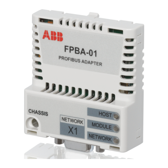
- Page 1 ABB Drives User’s Manual PROFIBUS DP Adapter Module FPBA-01...
- Page 3 PROFIBUS DP Adapter Module FPBA-01 User’s Manual 3AFE68573271 REV C EFFECTIVE: 09.01.2009 © 2009 ABB Oy. All Rights Reserved.
-
Page 5: Safety Instructions
Safety instructions Overview This chapter states the general safety instructions that must be followed when installing and operating the FPBA-01 PROFIBUS DP Adapter module. The material in this chapter must be studied before attempting any work on, or with, the unit. - Page 6 Safety instructions...
-
Page 7: Table Of Contents
Product training ..........13 Providing feedback on ABB Drives manuals ......14 Overview . -
Page 8: Table Of Contents
Actual values ..........56 The ABB Drives communication profile ......63 The Control Word and the Status Word . -
Page 9: Table Of Contents
FPBA-01 ........ - Page 10 Table of contents...
-
Page 11: Introduction
Safety instructions are featured in the first few pages of this manual. Overview contains a short description of the PROFIBUS protocol and the FPBA-01 PROFIBUS DP Adapter module, and a delivery checklist. Quick start-up guide contains a short description of how to set up the FPBA-01 PROFIBUS DP Adapter module. - Page 12 Communication profiles describes the communication profiles used in the communication between the PROFIBUS network, the FPBA-01 module, and the drive. Communication contains a description of how data is transmitted through the FPBA-01 module. Diagnostics explains how to trace faults with the status LEDs on the FPBA-01 module.
-
Page 13: Terms Used In This Manual
FPBA-01 PROFIBUS DP Adapter module The FPBA-01 PROFIBUS DP Adapter module is one of the optional fieldbus adapter modules available for ABB drives. The FPBA-01 is a device through which an ABB drive is connected to a PROFIBUS network. Parameter A parameter is an operating instruction for the drive. -
Page 14: Providing Feedback On Abb Drives Manuals
Providing feedback on ABB Drives manuals Your comments on our manuals are welcome. Go to www.abb.com/drives and select Document Library – Manuals feedback form (LV AC drives). Introduction... -
Page 15: Overview
Overview Overview This chapter contains a short description of the PROFIBUS standard and the FPBA-01 Adapter module, and a delivery checklist. PROFIBUS standard PROFIBUS is an open serial communication standard that enables data exchange between all kinds of automation components. There are three main variations of PROFIBUS:... -
Page 16: The Fpba-01 Profibus Dp Adapter Module
The FPBA-01 PROFIBUS DP Adapter module The FPBA-01 PROFIBUS DP Adapter module is an optional device for ABB drives which enables the connection of the drive to a PROFIBUS network. The drive is considered as a slave on the PROFIBUS network. Through the FPBA-01 PROFIBUS DP Adapter module, it is possible to: •... -
Page 17: Compatibility
Figure 1. The construction of the PROFIBUS link and the FPBA-01 Adapter module. Compatibility The FPBA-01 is compatible with all master stations that support the PROFIBUS DP protocol. Note: The PROFIBUS DP-V1 protocol is supported from FPBA-01 SW version 2.00A onwards. -
Page 18: Delivery Check
Delivery check The option package for the FPBA-01 PROFIBUS DP Adapter module contains: • PROFIBUS DP Adapter module, type FPBA-01 • this manual. Overview... -
Page 19: Quick Start-Up Guide
Quick start-up guide Overview This chapter presents the steps to take during the start-up of the FPBA-01 PROFIBUS DP Adapter Module with an ACS350, ACSM1 or ACS850 drive. For more detailed information, see the chapters Mechanical installation, Electrical installation, and... - Page 20 • Select the Fail Safe mode and enter a Failsafe Timeout value. Quick start-up guide...
- Page 21 • Set the message type, baud rate and node number. Quick start-up guide...
-
Page 22: Mechanical And Electrical Installation
Mechanical and electrical installation • Insert the FPBA-01 into its specified slot in the drive. • Fasten the screw. • Plug the fieldbus connector to the module. Drive configuration • Power up the drive. • The detailed procedure of activating the drive for communication with the module is dependent on the drive type. - Page 23 Parameter setting examples – ACS350 PROFIdrive communication profile with PPO Type 1 The start/stop commands and reference are according to the PROFIdrive profile. (See the PROFIBUS state machine on page 61.) The reference value ±16384 (4000h) corresponds to parameter 1105 REF1 MAX in forward and reverse directions. Quick start-up guide...
- Page 24 *Read-only or automatically detected/set ABB DRIVES communication profile with PPO Type 4 From the PLC programming point, the ABB DRIVES profile is similar to the PROFIdrive profile as shown in the first example. The start/stop commands and reference are according to the ABB DRIVES profile.
- Page 25 5102 NODE ADDRESS 5103 BAUDRATE 1500* 5104 TELEGRAM TYPE 4 (= PPO 4)* 5105 PROFILE 1 (= ABB DRIVES) 5401 DATA IN 1 4 (Status Word)* 5402 DATA IN 2 5 (Actual value 1)* 5403 DATA IN 3 106 (POWER)**...
-
Page 26: Parameter Setting Examples – Acsm1
5502 DATA OUT 2 2 (REF1)* 5503 DATA OUT 3 2501 (CRIT SPEED SEL)** 5504 DATA OUT 4 2502 (CRIT SPEED 1 LO)** 5505 DATA OUT 5 2503 (CRIT SPEED 1 HI)** 5127 FBA PAR REFRESH REFRESH *Read-only or automatically detected/set **Example Parameter setting examples –... - Page 27 51.03 BAUDRATE 12000* 51.04 TELEGRAM TYPE 1 (= PPO 1)* 51.05 PROFILE 0 (= PROFIdrive) 52.02 FBA DATA IN1 52.02 FBA DATA IN2 53.01 FBA DATA OUT1 53.02 FBA DATA OUT2 51.27 FBA PAR REFRESH REFRESH *Read-only or automatically detected/set PROFIdrive communication profile (Positioning Mode) with PPO Type 4 The start/stop commands and reference are according to the...
- Page 28 10.01 EXT1 START External 1 control source FUNC selection 22.01 SPEED FB SEL ENC1 Speed feedback SPEED** selection 34.02 EXT1 MODE 1/ P.FBA External 1 control mode 2SEL MAIN selection. Selection is CW.26 done by START_HOMING bit (bit 11 in Profibus Control Word).
- Page 29 66.05 POS ENABLE C.False Position reference generator is enabled by fieldbus only. 70.03 POS REF ENA C.False Position reference enable command from fieldbus only 51.01 FBA TYPE PROFIBUS Displays the type of the fieldbus adapter module. 51.02 NODE Profibus node address of ADDRESS the fieldbus module 51.03...
- Page 30 The position setpoint is scaled as follows: Drive parameter Setting 60.05 POS UNIT (Position unit) 60.08 POS2INT SCALE 100** **Example The position setpoint and actual values are scaled with the above example values as follows: 1000 / 100 = 10.00 60.05 POS UNIT Physical value 60.08 POS2INT SCALE...
- Page 31 C0Fh (3087 decimal)=> OPERATING (Start Homing procedure.) ABB DRIVES communication profile (Speed/Torque Control Mode) with PPO Type 4 The start/stop commands and reference are according to the ABB DRIVES profile Speed Control Mode. When Reference 1 (REF1) is used, a reference value of ±20000 (4E20h) corresponds to the reference set by parameter 25.02...
- Page 32 The table below gives the recommended drive parameter settings. Drive Name Setting Description parameter 50.01 FBA ENABLE ENABLE Communication enable between the drive and the fieldbus module 50.04 FBA REF1 SPEED Fieldbus reference 1 mode MODESEL selection 50.05 FBA REF2 TORQUE Fieldbus reference 2 mode MODESEL...
- Page 33 51.05 PROFILE 1(= ABB Control Word according to Drives) the ABB Drives profile. 52.01 FBA DATA IN1 4* Status Word (PZD 1) 52.02 FBA DATA IN2 5 Actual value 1 52.03 FBA DATA IN3 6 Actual value 2 53.01 FBA DATA...
- Page 34 The table below gives the recommended drive parameter settings. Drive parameter Setting 50.01 Fba enable Enable 50.04 Fba ref1 modesel Speed 10.01 Ext1 start func 21.01 Speed ref1 sel FBA ref1 51.01 FBA type 1 = FPBA-xx PROFIBUS DP adapter module* 51.02 NODE ADDRESS 51.03 BAUDRATE 12000*...
-
Page 35: Mechanical Installation
Mounting The FPBA-01 is to be inserted into its specific position in the drive. The module is held in place with plastic pins and one screw. The screw also provides the earthing of the fieldbus cable shield connected to the module. - Page 36 Mechanical installation...
-
Page 37: Electrical Installation
Electrical installation Overview This chapter contains: • general cabling instructions • instructions for setting module node address number and bus termination • instructions for connecting the module to the PROFIBUS DP network. WARNING! Before installation, switch off the drive power supply. Wait five minutes to ensure that the capacitor bank of the drive is discharged. -
Page 38: Profibus Connection
PROFIBUS connection The bus cable is connected to connector X1 on the FPBA-01. The connector pin allocation described below follows the PROFIBUS standard. Description SHLD Alternate cable shield connection. Connected to connector housing. Not used Data positive (Conductor 1 in twisted pair). - Page 39 It is recommended to use a PROFIBUS-approved D-SUB 9 connector. These connectors have a built-in termination network and inductors for station capacitance compensation. The cable should be connected to the D-SUB connector as follows: 1A 1B 2A 2B Grounding clamp/ Strain relief Figure 2.
-
Page 40: Bus Termination
Therefore, the D-SUB connectors at the first and last modules of the bus must have built-on termination switched on. See the diagram below. The FPBA-01 module is able to supply power for an active-type termination circuitry (30 mA max.). PROFIBUS... -
Page 41: Drive Configuration
FPBA-01 PROFIBUS DP Adapter module. PROFIBUS connection configuration After the FPBA-01 PROFIBUS DP Adapter module has been mechanically and electrically installed according to the instructions in previous chapters, the drive must be prepared for communication with the module. - Page 42 Table 1. FPBA-01 configuration parameters – Group A Par. Parameter name Alternative settings Default setting FBA TYPE (Read-only) PROFIBUS DP NODE ADDRESS 0 to 126 BAUD RATE* (12000) 12 Mbit/s; (6000) 6 Mbit/s; 1500 (3000) 3 Mbit/s; (1500) 1.5 Mbit/s;...
- Page 43 ACSM1 drive. 5 PROFILE This parameter is used to select which communication profile is used. The FPBA-01 supports the PROFIdrive, ABB Drives and Transparent 16 profiles. With an ACSM1 drive, a PROFIdrive positioning mode and the Transparent 32 profile are also supported.
- Page 44 Communication profiles. 6 T16 SCALE Reference multiplier/actual value divisor for the FPBA-01. The parameter is effective only when the Transparent 16 profile is selected AND the drive is using the DCU communication profile. With an ACS350, the speed reference from the PLC is multiplied by the value of this parameter.
- Page 45 Table 2. FPBA-01 configuration parameters – Group B Par. Parameter name Alternative settings Default setting DATA OUT 1 0 to 9999 1 (Control word) (master to drive) Format: xxyy, where 11 (Control xx = parameter group and word 32-bit)* yy = parameter index.
- Page 46 The virtual address area of the drive control is allocated as follows: Virtual Description Data DATA address length IN only Control word* 16-bit Reference 1 (REF1)* 16-bit Reference 2 (REF2)* 16-bit Status word 16-bit Actual value 1 (ACT1) 16-bit Actual value 2 (ACT2) 16-bit 7…10 Reserved...
- Page 47 below are recommended. (FBA REFx mode is selected with ACSM1 drive parameter 50.04/50.05.) The information in the table is applicable only if PPO messaging is used (see parameter group A, parameter number 4 “TELEGRAM TYPE” on page 42). If standard telegrams (STx) are used, virtual addresses for standard telegrams (ST1 and ST2) are updated automatically.
- Page 48 Table 3. FPBA-01 configuration parameters – Group C Par. Parameter name Alternative settings Default setting DATA IN 1 0 to 9999 4 (Status word) (drive to master) Format: xxyy, where 14 (Status word xx = parameter group and 32-bit)* yy = parameter index.
-
Page 49: Control Locations
ABB drives can receive control information from multiple sources including digital inputs, analogue inputs, the drive control panel and a communication module (e.g. FPBA-01). ABB drives allow the user to separately determine the source for each type of control information (Start, Stop, Direction, Reference, Fault Reset, etc.). - Page 50 Drive configuration...
-
Page 51: Master Configuration
FPBA-01 PROFIBUS Adapter module. Configuring the system After the FPBA-01 PROFIBUS DP Adapter module has been mechanically and electrically installed according to the instructions in previous chapters, and has been initialised by the drive, the master station must be prepared for communication with the module. - Page 52 Master configuration...
-
Page 53: Communication Profiles
With the FPBA-01 module, the PROFIBUS network may employ either the PROFIdrive profile or the ABB Drives profile. Both are converted to the DCU/FBA profile (detailed in the drive documentation) by the FPBA-01 module. In addition, two Transparent modes –... - Page 54 If Standard Telegrams (ST) are used, the communication profile is selected automatically. The following sections describe the Control word, the Status word, references and actual values for the PROFIdrive and ABB Drives communication profiles. Refer to the drive manuals for details on the DCU communication profile.
-
Page 55: The Profidrive Communication Profile
ABB drives can receive control information from multiple sources including analogue and digital inputs, the drive control panel and a communication module (e.g. FPBA-01). In order to have the drive controlled through PROFIBUS, the communication module must be defined as the source for control information, e.g. Reference. -
Page 56: Actual Values
References in positioning mode (with an ACSM1 drive only) In positioning mode, references are 16-bit or 32-bit words. A 32-bit reference contains a sign bit and a 31-bit integer. A negative reference (indicating reversed direction of rotation) is formed by calculating the two’s complement from the corresponding positive reference. - Page 57 Table 4. The Control Word for the PROFIdrive communication profile (PROFIBUS Parameter 967). The upper case boldface text refers to the states shown in Figure 4. Proceed to STATE/Description Bit Name Value Speed control mode Positioning mode 0 ON Proceed to READY TO OPERATE. OFF1 Emergency OFF, stop by the selected deceleration ramp.
- Page 58 Proceed to STATE/Description Bit Name Value Speed control mode Positioning mode Normal operation. Normal operation. No Proceed to RAMP intermediate stop. FUNCTION GENERATOR: ENABLE ACCELERATOR. Halt ramping (Ramp Intermediate stop. Function Generator output held). Normal operation. Proceed Activate traversing task (0 ⇒...
- Page 59 Proceed to STATE/Description Bit Name Value Speed control mode Positioning mode Vendor-specific bit as defined by PROFIdrive parameter 935. Vendor-specific bit as defined by PROFIdrive parameter 936. Vendor-specific bit as defined by PROFIdrive parameter 937. Table 5. The Status Word for the PROFIdrive communication profile (PROFIBUS Parameter 968).
- Page 60 Bit Name Value STATE/Description Speed control mode Positioning mode AT_SETPOINT OPERATING. Actual value equals reference value (i.e. is within tolerance limits). Actual value differs from reference value (= is outside tolerance limits). REMOTE Drive control location: REMOTE. Drive control location: LOCAL. Actual frequency or Target position reached.
-
Page 61: State Machine
SWITCH-ON PROFIBUS MAINS OFF INHIBIT (SW Bit6=1) State Machine OFF1 (CW Bit0=0) Power ON CW = Control Word NOT READY SW = Status Word TO SWITCH ON (SW Bit0=0) A B C D = Speed = Input Current RFG = Ramp Function (CW=xxxx xxxx xxxx x110) Generator (CW Bit3=0) - Page 62 BASIC STATE: Operating* (SW Bit10,13=1) (CW Bit4,5=1 (CW Bit11=1) CW Bit6 ⇒ edge 0 HOMING RUNNING (SW Bit10,11,13=0) HOMING READY (SW Bit10,11,13=1) (CW Bit11=0) Traversing task PROFIBUS active (SW Bit10,13=0) State Machine for PROFIdrive (CW Bit6 edge (CW Bit5=0) ⇒ Positioning Mode Braking with ramp...
-
Page 63: The Abb Drives Communication Profile
ABB drives can receive control information from multiple sources including analogue and digital inputs, the drive control panel and a communication module (e.g. FPBA-01). In order to have the drive controlled through the fieldbus, the module must be defined as the source for control information, e.g. - Page 64 Scaling References are scaled as shown below. Note: The values of REF1 MAX and REF2 MAX are set by drive parameters. See the drive documentation for further information. Fieldbus Drive REF2: 10000 REFx MAX REF1: 20000 REFx MIN -(REFx MIN) REF2: -10000 -(REFx MAX) REF1: -20000...
- Page 65 Actual values Actual values are 16-bit words containing information on the operation of the drive. The functions to be monitored are selected by a drive parameter. Scaling Actual values are scaled as shown below. Note: The values of REF1 MAX and REF2 MAX are set by drive parameters.
- Page 66 Table 6. The Control Word for the ABB Drives communication profile. The upper case boldface text refers to the states shown in Figure 4. Name Value STATE/Description OFF1_ Proceed to READY TO OPERATE. CONTROL Stop along currently active deceleration ramp.
- Page 67 Name Value STATE/Description RAMP_HOLD Enable ramp function. Proceed to RAMP FUNCTION GENERATOR: ACCELERATOR ENABLED. Halt ramping (Ramp Function Generator output held). RAMP_IN_ Normal operation. Proceed to OPERATING. ZERO Note: This bit is effective only if the fieldbus interface is set as the source for this signal by drive parameters.
- Page 68 Table 7. The Status Word for the ABB Drives communication profile. The upper case boldface text refers to the states shown in Figure 6. Name Value STATE/Description RDY_ON READY TO SWITCH ON. NOT READY TO SWITCH ON. RDY_RUN READY TO OPERATE.
- Page 69 Name Value STATE/Description ABOVE_ Actual frequency or speed equals or exceeds LIMIT supervision limit (set by drive parameter). Valid in both directions of rotation. Actual frequency or speed within supervision limit. EXT_CTRL_ External Control Location EXT2 selected. External Control Location EXT1 selected. EXT_RUN_ External Run Enable signal received.
- Page 70 (CW Bit5=0) (CW=xxxx x1xx xxx1 1111) RFG: OUTPUT ENABLED (CW Bit6=0) (CW=xxxx x1xx xx11 1111) RFG: ACCELERATOR state ENABLED condition (CW=xxxx x1xx x111 1111) rising edge OPERATION the bit (SW Bit8=1) Figure 6. State machine, ABB Drives communication profile Communication profiles...
-
Page 71: Communication
PROFIBUS slave device configuration messages. PROFIBUS DP The FPBA-01 module supports the PROFIBUS DP (DP-V0) protocol according to the IEC 61784 and EN 50170 standards. PROFIBUS DP-V0/DP-V1 is a distributed I/O system which enables the master to use a large number of peripheral modules and field devices. -
Page 72: Communication Start-Up
Communication start-up The following Service Access Points (SAPs) are used to initiate DP communication: SAP no. Short Name Name Default Data_Exch Cyclical Data Exchange SAP (0) (Write_Read_Data) Global_Control Global Control Service Get_Cfg Read Configuration Data Slave_Diag Read Diagnostic Data Set_Prm Send Parameter Data Chk_Cfg Check Configuration Data... - Page 73 PROFIBUS SD2 telegram for Default SAP (0) and SAP 58-62 PROFIBUS typically uses SD2 telegrams for DP communication. The structure of an SD2 telegram is shown below. DP header DP trailer SD LE LEr SD *DSAP *SSAP DU FCS ED 68h x 68h xx x…...
- Page 74 Default SAP (SAP 0) (Data_Exchange) Allows the master to send output data to a slave station and to simultaneously request input data from the same station. Outp_Data (Output Data) DU length: 4 to 28 bytes (depending on the selected PPO message/ Standard telegram type) Inp_Data (Input Data) DU length: 4 to 28 bytes (depending on the selected PPO message/...
- Page 75 SAP 58 (Global_Control) This SAP is used to send special commands addressed to a single slave, a special group of slaves, or all slaves at once (broadcast). Global_Control Type: Octet String - Length: 2 Description Byte GC_Command 0 0 x x x x x 0 Reserved Clear Data 0 = Do not clear output...
- Page 76 Time after which a slave station is allowed to send response frames to the master. Calculated by multiplying the hex value with t (time required for transmitting one bit). 4 - 5 0959h Vendor Identification (for the FPBA-01: 0959h) Group Identification Communication...
- Page 77 DPV1_Status_1 (DP-V1 only) x 0 x 0 0 x x x Dis_Start_Control (Disable Stop-Bit Control) 0 = Start bit monitoring in receiver enabled 1 = Start bit monitoring in receiver disabled Dis_Stop_Control (Disable Stop-Bit Control) 0 = Stop bit monitoring in receiver enabled 1 = Stop bit monitoring in receiver disabled WD_Base (Watchdog time base) 0 = 10 ms...
- Page 78 DPV1_Status_2 (DP-V1 only) (Not supported) x x x x x x 0 x Chk_Cfg_Mode 0 = Chk_Cfg according to EN 50170 (default state) 1 = User-specific evaluation of Chk_Cfg Reserved. To be parameterised with ‘0’. Enable_Update_Alarm 0 = Enable_Update_Alarm disabled 1 = Enable_Update_Alarm enabled Enable_Status_Alarm 0 = Enable_Status_Alarm disabled...
- Page 79 Structured_Length (Default) Length of the structured Prm telegram. (User parameter length is 23 bytes + 4 header bytes.) Structure_Type 129: USER_PRM_DATA Slot_Number Set to 0. Reserved. User_Prm_Data (Parameter Data Extended) Type: Octet String - Length: 23 Header byte (default) 0 0 0 0 0 x 0 x Fail-safe mode.
- Page 80 31 - 32 0-65536 Fail-safe, PZD8 33 - 34 0-65536 Fail-safe, PZD9 35 - 36 0-65536 Fail-safe, PZD10 The extended Parameter Data bytes are configured via the PROFIBUS network configuration tool. The functions are defined in the GSD file. Communication...
- Page 81 SAP 62 (Chk_Cfg) With this telegram, the master will send the selected data exchange (Write_Read_Data) telegram type code to slave SAP 62. The table below gives the typical hexadecimal values (DU Byte 0…n) that are sent to the drive in order to select the PPO type or standard telegram (ST).
- Page 82 1 = Consistency of entire length For example, 11110001 = F1 = PPO3 Also data non-consistent over the entire message is supported by the FPBA-01. The cyclical frame types supported by the module are defined in the GSD file. Communication...
- Page 83 SAP 60 (Slave_Diag) This SAP gives diagnostic information on the slave station. Diag_Data (Diagnostic Data) Type: Octet String - Length: 6 (Standard) + 2 (Extended Diagnosis) (DP-V0 mode) + 5 (Extended Diagnosis) (DP-V1 mode) Note: During initialisation, the module only sends the standard part of the message.
- Page 84 Ext_Diag_Data (0x02) (DP-V0 only) The number of bytes (including this byte) reserved for Extended Diagnosis Header Byte (DP-V1 only) The complete header consists of 5 bytes with the FPBA-01. Block length in bytes including header Diagnostic type 00 = Device-related diagnostic according to PROFIdrive 3.1.
- Page 85 0 0 0 0 0 0 Communication temporarily lost Communication permanently lost Reserved *The FPBA-01 is operated in DP-V1 mode. The Diagnostics information is according to PROFIdrive 3.1. **The FPBA-01 is operated in DP-V0 (DP) mode. The Diagnostics information is according to PROFIdrive 2.0.
-
Page 86: Other Saps For Dp-V1 Communication
Other SAPs for DP-V1 communication Master Master Slave Short Name Meaning Class Server SAP Read, Write, Alarm Alarm SAP Alarm Resource Req PDU Mgmt. SAP 48..0 Communication Abort, Read/Write, Data_Transfer Set_Slave_Add Change Station Address (C2 Master) Communication... -
Page 87: Cyclical Message Types
Cyclical message types PPO types Parameter Process data identification Fixed area Freely mappable area OUT area VALUE CW REF PZD3 PZD4 PZD5 PZD6 PZD7 PZD8 PZD9 PZD10 IN area VALUE SW ACT PZD3 PZD4 PZD5 PZD6 PZD7 PZD8 PZD9 PZD10 Type 1 DP-V0 Type 2... -
Page 88: Standard Telegram (St) Types
Standard telegram (ST) types PZD1 PZD2 STW1 NSOLL_A OUT area Control word 1 Speed setpoint A ZSW1 NIST_A IN area Status word 1 Speed actual value A PZD1 PZD2…3 PZD4 STW1 NSOLL_B STW2 OUT area Control word 1 Speed setpoint B Control word 2 ZSW1 NIST_B... -
Page 89: Parameter Handling In Cyclic Communication (Dp)
Parameter handling in cyclic communication (DP) In cyclic PROFIBUS DP communication, parameter data is transferred in PPO message types 1, 2 and 5 (see Figure 8.). The Parameter Identification part consists of eight bytes (see below). Parameter Identification Process Data CW REF VALUE (PD1, PD2...) - Page 90 Response label (Acknowledgement from Slave to Master) Ackn. Function No response Transfer parameter value (word) Transfer parameter value (double word) Transfer description element Transfer parameter value (array word) Transfer parameter value (array double word) Transfer number of array elements Task cannot be executed, followed by error number 0 = Illegal parameter number 1 = Parameter value cannot be changed 2 = Lower or upper limit violated...
- Page 91 The allocation of drive control/actual words, drive parameters and PROFIdrive parameters to the Parameter Identification part of the PPO type is shown below. The Index column corresponds to the parameter number (PNU) in the ID part of Parameter Identification. The Sub-index column corresponds to the IND part of Parameter Identification.
- Page 92 Note: Continuous (cyclic) writing of PROFIdrive parameters should be avoided as the values of these parameters are stored in the flash memory of the FPBA-01. The estimated lifetime of the flash memory is 100,000 program/erase cycles, and continuous writing will cause the memory to fail prematurely.
-
Page 93: Parameter Data Transfer Examples
Parameter data transfer examples Note: Only the ‘Data unit’ part of the telegram is presented in the examples. See Figure on page 73. Example 1: Reading a drive parameter (or data set) To determine the parameter number and subindex for drive parameter reading, convert the drive parameter group number and the parameter index number to hexadecimal. - Page 94 Example 2: Writing a drive parameter (or data set) To determine the parameter number and subindex for drive parameter writing, convert the drive parameter group number and the parameter index number to hexadecimal. The index number is the subindex (IND), and the group number is the parameter number (PNU).
- Page 95 Example 3: Reading a PROFIdrive parameter (word) In this example, PROFIBUS Parameter 918 is used to read the station number of the slave. Request (Parameter value read) Parameter Number (918 decimal) Param. Value Request 13 96 00 00 00 00 00 00 04 7F 34 15 Read: header trailer...
- Page 96 Example 4: Writing a PROFIdrive parameter (word) In this example, current parameter settings are saved to the FLASH memory of the drive. This is done by setting the value of PROFIBUS Parameter 971 (3CBh) to 1. Note that the drive always observes the Control Word (CW) and Reference (REF) bytes.
- Page 97 See also the User’s Manual of the drive for drive- specific fault codes. The implementation of the PROFIdrive profile in the FPBA-01 supports the storage of the active and the five latest occurred different faults in the fault buffer. The fault codes can be accessed by PROFIdrive parameters 945, 947 and 948 (see page 123).
- Page 98 Example 6: Configuring the process data written to the drive PROFIBUS parameter 915 can be used to define which data is written cyclically to a drive parameter as application-specific process data. In the example below, the value of drive parameter 12.02 (0Ch.02h) is selected to be taken from PZD3.
- Page 99 Example 7: Configuring the process data read from the drive PROFIBUS Parameter 916 can be used to define which data is read cyclically from the drive as application-specific process data. In the example below, drive parameter 1.04 (01h.04h) is selected to be transmitted by the drive as PZD3.
-
Page 100: Dp-V1 Read/Write Request Sequence
If the write request is valid, the FPBA-01 acknowledges it with DP- V1 write response code 5Fh with no data. The master will then send a read request. If the FPBA-01 is still busy performing the internal parameter request, it will return a negative response with the DP-V1 error code B5h (State conflict). - Page 101 FPBA-01 has the PROFIdrive response data ready. If the write request is invalid, a negative response is returned with a DP-V1 error code (see Table 10). Communication...
- Page 102 PROFIBUS SD2 telegram for SAP 51 The Read/Write service uses a variable-length PROFIBUS SD2 telegram shown below. DP header DP trailer SD LE LEr SD DSAP SSAP DU FCS ED 68h x 68h xx x… SD = Start Delimiter LE = Length LEr = Length repeated DA = Destination Address SA = Source Address...
- Page 103 Table 8. DP-V1 function numbers Value Meaning 0x48 Idle REQ, RES 0x51 Data transport REQ, RES 0x56 Resource manager REQ 0x57 Initiate REQ, RES 0x58 Abort REQ 0x5C Alarm REQ, RES 0x5E Read REQ, RES 0x5F Write REQ, RES 0xD1 Data transport negative response 0xD7 Initiate negative response...
- Page 104 10 (0x0A) Application 0 = Read error 1 = Write error 2 = Module failure 3 … 7 = Reserved 8 = Version conflict 9 = Feature not supported 10 … 15 = User-specific 11 (0x0B) Access 0 = Invalid index 1 = Write length error 2 = Invalid slot 3 = Type conflict...
- Page 105 Parameter Address of the parameter that is being 1 … 65535 Word Index accessed. “0” is allowed by FPBA-01. Subindex Addresses the first array element of the 0 … 65535 Word parameter or the beginning of a string access or the text array, or the description element that is being accessed.
- Page 106 Drive To be set to 1. 0 … 255 Object ID No. of Number of parameters that are present 1 … 37 Parameters in the response. Format* See Table 13. See Table Number of Number of values following. 0 … 234 Values* Values* The values of the request.
- Page 107 0x44 Error 0x45 … 0xFF (Reserved) Table 14. PROFIdrive Parameter Request error codes Error # Meaning Used at Impermissible parameter Access to unavailable parameter number Parameter value cannot be Change access to a parameter value changed that cannot be changed Low or high limit exceeded Change access with value outside the limits...
- Page 108 Response too long The length of the current response exceeds the maximum transmittable length Parameter address Illegal value or value that is not impermissible supported for the attribute, number of elements, parameter number or sub- index, or a combination Illegal format Write request: Illegal format or format of parameter data that is not supported Number of values inconsistent...
- Page 109 Internal buffer Buffer overflow Internal communication Communication error between module and drive Communication...
- Page 110 Parameter data transfer examples The following examples show how parameter data is transferred using the DP-V1 mechanisms READ and WRITE. Note: Only the “Data unit” part of the SD2 telegram is presented in the examples. See Figure on page 102. Example 1a: Reading a drive parameter (array element) Drive parameters are addressed so that the drive parameter group corresponds to the parameter index (PNU), and the drive...
- Page 111 Positive Read response to DP-V1 Read request: Function number Slot number Index Data length Response reference (mirrored) Response ID Drive object ID Number of parameters Format (42h = Word) Number of values Parameter value 5E 01 2F 08 05 01 01 01 42 01 05 64 header trailer DP-V1 Response...
- Page 112 Example 1b: Reading 3 drive parameters (multi-parameter) In this example, three parameters (12.04, 20.08 and 30.19) are read using one telegram. DP-V1 Write request (Read parameter value): Function number Slot number Index Data length Request reference Request ID (01h = Request Parameter) Drive object ID Number of parameters Attribute (10h = Value)
- Page 113 Positive Read response to DP-V1 Read request: Function number Slot number Index Data length Response reference (mirrored) Response ID Drive object ID Number of parameters Format (42h = Word) Number of values Parameter value 5F 01 2F 10 06 01 01 03 42 01 01 90 •••...
- Page 114 Example 2a: Writing a drive parameter (one array element) Drive parameters are addressed so that the drive parameter group corresponds to the parameter index (PNU), and the drive parameter number within that group corresponds to the subindex (IND). In the following example, a value is written to drive parameter number 12.02 (0C.02h).
- Page 115 Example 2b: Writing 2 drive parameters (multi-parameter) In this example, the values 300 (12Ch) and 500 (1F4h) are written to drive parameters 12.02 (0C.02h) and 20.08 (14.08h) respectively using one telegram. Function number Slot number Index Data length Request reference Request ID (02h = Change Parameter) Drive object ID Number of parameters...
- Page 116 Slot number Slot number Index Data length Request reference (mirrored) Response ID Drive object ID (mirrored) Number of parameters 5E 01 2F 04 08 02 01 02 PROFIdrive V3 header trailer DP-V1 Response Parameter Channel Example 3: Reading a PROFIdrive parameter In this example, PROFIBUS parameter No.
- Page 117 See also the User’s Manual of the drive for drive specific fault codes. The implementation of the PROFIdrive profile in the FPBA-01 supports the storage of the active and the five latest occurred different faults in the fault buffer. The fault codes can be accessed by PROFIdrive parameters 945, 947 and 948 (see page 123).
- Page 118 DP-V1 Write request Function number Slot number Index Data length Request reference Request ID (02h = Change) Drive object ID Number of parameters Attribute (10h = Value) Number of elements Parameter index Subindex Format (42h = Word) Number of values Value 5F 01 2F 0E 0A 02 01 01 10 01 03 93 00 03 42 01 0C 06 header...
- Page 119 Example 5: Determining the source of process data read from the drive PROFIBUS Parameter No. 916 (394h) can be used to define which data is read cyclically from the drive as application-specific process data. In the example below, the parameter is used to determine which drive parameter the contents of PZD3 are taken from.
- Page 120 Communication...
-
Page 121: Diagnostics
Diagnostics LED indications The FPBA-01 module is equipped with three bicolour diagnostic LEDs. The LEDs are described below. Name Colour Function Green Connection to host OK HOST Establishing communication to host, Blinking red or communication to host lost Green Module status OK... - Page 122 Name Colour Function Blinking green Establishing network connection NETWORK Green Network connection OK Blinking red Network connection lost Diagnostics...
-
Page 123: Profidrive Parameters
PROFIdrive parameters PROFIdrive profile-specific parameters Param- Data type Description eter Array [10] Assignment PZD1 to PZD10 in PPO-write Unsigned16 Array [10] Assignment PZD1 to PZD10 in PPO-read Unsigned16 Unsigned16 Node address. Writing this parameter will change the node address. Module re-start required. Octet String4 Device system number. - Page 124 Note: This parameter is not available if Standard telegram ST1 or ST2 is selected. Unsigned16 Selection switch for communication profile. Value Mode PROFIdrive 8001h ABB Drives 8002h Transparent 16 8003h Transparent 32 8004h PROFIdrive positioning mode Unsigned16 Selection switch for Control word, bit 11.
- Page 125 Param- Data type Description eter Unsigned16 Selection switch for Control word, bit 12. (See parameter 933 for coding) Unsigned16 Selection switch for Control word, bit 13. (See parameter 933 for coding) Unsigned16 Selection switch for Control word, bit 14. (See parameter 933 for coding) Unsigned16 Selection switch for Control word, bit 15.
- Page 126 Param- Data type Description eter Unsigned16 Number of faults occurred. Writing a zero clears the value. Unsigned16 **Last alarm Unsigned16 **Second last alarm Unsigned16 **Third last alarm Unsigned16 **Fourth last alarm Unsigned16 **Fifth last alarm Unsigned16 Sixth last alarm (not supported) Unsigned16 Seventh last alarm (not supported) Unsigned16...
- Page 127 Param- Data type Description eter Unsigned16 Load parameter record Value Description No action Restore factory settings The parameter must do a zero-to-one transition and the motor must be stopped. Unsigned16 Save parameter record Value Description No action Save the drive parameters to non-volatile memory The parameter must do a zero-to-one transition and the motor must be stopped.
-
Page 128: I&M (Identification & Maintenance) Records
I&M (Identification & Maintenance) records I&M records can be read e.g. with the DTM tool. The FPBA-01 supports the mandatory I&M0 record as well as the optional I&M1 and I&M2 records. Call-REQ-PDU telegram for read/write access to I&M records: Contents... -
Page 129: Response Structure For I&M1 (Read/Write)
Response structure for I&M1 (Read/Write) Contents Size Coding Header Manufacturer-specific 10 Octets – I&M0 TAG_FUNCTION 32 Octets Device function or task block TAG_LOCATION 22 Octets Device location Response structure for I&M2 (Read/Write) Contents Size Coding Header Manufacturer-specific 10 Octets – I&M0 INSTALLATION_DATE 16 Octets... - Page 130 PROFIdrive parameters...
-
Page 131: Definitions And Abbreviations
Definitions and abbreviations PROFIBUS definitions Acyclic Communication in which messages are sent only once Communication on request Array Parameter consisting of data fields of equal data type Broadcast Non-acknowledged message from master to all bus participants (compare Multicast) Command Word See Control Word Communication Any object of a real device that can be communicated... - Page 132 Master Control system with bus initiative. In PROFIBUS terminology, master stations are also called active stations. Multicast Non-acknowledged message from master to one group of bus participants (compare Broadcast) Name Symbolic name of a parameter Nibble Set of 4 bits Object Dictionary Local storage of all Communication Objects recognised by a device...
-
Page 133: Profibus Abbreviations
Warning Signal caused by an existing alarm which does not lead to tripping of the device PROFIBUS abbreviations The text in italics is the original German term. .con Confirmation .ind Indication .req Request .res Response Actual Value Istwert Request Label/Response Label Auftragskennung/Antwortkennung Application Layer Interface Communication Reference... - Page 134 see ACT KR (KB) see CR Process Automation Prozessautomatisierung Process Data Prozessdaten Parameter Identification Parameter-Kennung Parameter Identification Value Parameter-Kennung-Wert Parameter Number Parameternummer Parameter/Process Data Object Parameter-/Prozessdaten-Objekt Parameter Value Parameter-Wert see PD PZDO Process Data Object Prozessdatenobjekt Service Access Point Reference Sollwert Request Signal Spontanmeldung...
-
Page 135: Technical Data
Technical data FPBA-01 Enclosure: Mounting: Into the option slot on the drive. Degree of protection: IP20 Ambient conditions: The applicable ambient conditions specified for the drive in its manuals are in effect. Indicators: Three bicolour LEDs (HOST, MODULE, NETWORK) Connectors: •... - Page 136 General: • Estimated min. lifetime: 100 000 h • All materials UL/CSA-approved • Complies with EMC standards EN 50081-2 and EN 50082-2 • Bus interface functionally isolated from drive Technical data...
-
Page 137: Profibus Link
Compatible devices: All PROFIBUS-compliant devices Medium: Shielded twisted pair RS-485 cable (PROFIBUS- approved cable recommended) • Termination: 220 ohms, or active termination circuitry at each end of trunk cable (termination not built in the FPBA-01 module) • Specifications: Line B Line A... - Page 138 Technical data...
- Page 140 ABB Oy ABB Inc. ABB Beijing Drive AC Drives Automation Technologies Systems Co. Ltd. P.O. Box 184 Drives & Motors No. 1, Block D, FIN-00381 HELSINKI 16250 West Glendale Drive A-10 Jiuxianqiao Beilu FINLAND New Berlin, WI 53151 Chaoyang District...