ABB FDNA-01 User Manual
Devicenet adapter module
Hide thumbs
Also See for FDNA-01:
- Quick installation and start-up manual (2 pages) ,
- Quick installation and start-up manual (2 pages)

Related Manuals for ABB FDNA-01


Summary of Contents for ABB FDNA-01
- Page 1 Options for ABB drives, converters and inverters User’s manual FDNA-01 DeviceNet adapter module...
-
Page 2: List Of Related Manuals
List of related manuals See section Related manuals on page 16. - Page 3 User’s manual FDNA-01 DeviceNet adapter module Table of contents 1. Safety 4. Mechanical installation 5. Electrical installation 6. Start-up 3AFE68573360 Rev E © 2012 ABB Oy All Rights Reserved. EFFECTIVE: 2012-04-04...
-
Page 5: Table Of Contents
Example topology of the DeviceNet link ....24 FDNA-01 DeviceNet adapter module ....25 Layout of the adapter module . - Page 6 Parameter setting examples – ACS355 ....50 ABB Drives profile ......50 ODVA AC/DC drive profile .
- Page 7 Torque Actual (AC/DC drive object)....87 ABB Drives communication profile ..... . . 88 Control word and Status word .
- Page 8 ....109 ABB Drives profile with set speed assembly ... 111 ABB Drives profile with set speed plus drive parameters assembly .
- Page 9 FDNA-01 ........
- Page 10 Product training ........167 Providing feedback on ABB Drives manuals ....167...
-
Page 11: Safety
Safety 11 Safety What this chapter contains The chapter presents the warning symbols used in this manual and the safety instructions which you must follow when installing an optional module into a drive, converter or inverter. If ignored, physical injury or death may follow, or damage may occur to the equipment. -
Page 12: Use Of Warnings
12 Safety Use of warnings Warnings caution you about conditions which can result in serious injury or death and/or damage to the equipment and advise on how to avoid the danger. The following warning symbols are used in this manual: Electricity warning warns of hazards from electricity which can cause physical injury and/or damage to the equipment. -
Page 13: Safety In Installation
Safety 13 Safety in installation These warnings are intended for all who install an optional module into a drive, converter or inverter. WARNING! Ignoring the following instructions can cause physical injury or death, or damage to the equipment. • Only qualified electricians are allowed to install and maintain the drive, converter or inverter! •... - Page 14 14 Safety...
-
Page 15: About The Manual
About the manual What this chapter contains This chapter introduces this manual. Applicability This manual applies to the FDNA-01 DeviceNet adapter module (+K451), SW version 0.223 or later. Compatibility The FDNA-01 DeviceNet adapter module is compatible with the following drives: •... -
Page 16: Target Audience
Purpose of the manual The manual provides information on installing, commissioning and using an FDNA-01 DeviceNet adapter module. Related manuals The related manuals are listed below. Code (English) Drive user’s manuals... -
Page 17: Before You Start
Document library on the Internet the inside of the back cover. For manuals not available in the Document library, contact your local ABB representative. Before you start It is assumed that the drive is installed and ready to operate before you start the installation of the adapter module. -
Page 18: Contents
• About the manual introduces this manual. • Overview of the DeviceNet network and the FDNA-01 module contains a short description of the DeviceNet network and the adapter module. • Mechanical installation contains a delivery checklist and instructions on mounting the adapter module. -
Page 19: Terms And Abbreviations Used In This Manual
ACQ810, ACS850 and ACSM1 drives FDNA-01 DeviceNet One of the optional fieldbus adapter modules adapter module available for ABB drives. FDNA-01 is a device through which an ABB drive is connected to a DeviceNet serial communication bus. Least significant word... -
Page 20: Devicenet Terms And Abbreviations
Input In the ODVA DeviceNet specification the word ‘input’ is used to describe data flow from a device (such as FDNA-01) to the network. I/O assembly selection Smart networked devices (like FDNA-01) can produce and/or consume more than one I/O value. - Page 21 A Poll Command is directed towards a single, specific slave (point- to-point, FDNA-01 always acts as a slave). A master must transmit a separate Poll Command Message for each of its slaves that is to be polled.
- Page 22 22 About the manual...
-
Page 23: Overview Of The Devicenet Network And The Fdna-01
Overview of the DeviceNet network and the FDNA-01 module 23 Overview of the DeviceNet network and the FDNA-01 module What this chapter contains This chapter contains a short description of the DeviceNet network and the FDNA-01 DeviceNet adapter module. DeviceNet network The DeviceNet network has a linear bus topology. -
Page 24: Example Topology Of The Devicenet Link
24 Overview of the DeviceNet network and the FDNA-01 module Example topology of the DeviceNet link An example of an allowable topology is shown below. Trunk line Node Node Node Node Node Node Terminating Resistor Node Node Node Drop line... -
Page 25: Fdna-01 Devicenet Adapter Module
FDNA-01 DeviceNet adapter module The FDNA-01 DeviceNet Adapter module is an optional device for ABB drives. It enables the connection of the drive to a DeviceNet network. The drive is considered a slave in the DeviceNet network. Through the adapter module you can: •... -
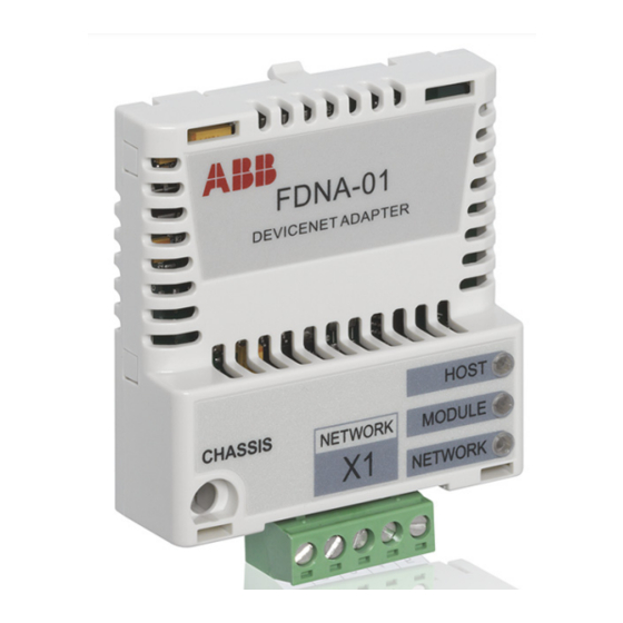
Page 26: Layout Of The Adapter Module
26 Overview of the DeviceNet network and the FDNA-01 module Layout of the adapter module Diagnostic LEDs (see chapter Diagnostics) Bus connector X1 (see chapter Electrical installation) Mounting screw... -
Page 27: Mechanical Installation
This chapter contains a delivery checklist and instructions on mounting the adapter module. WARNING! Follow the safety instructions given in this manual and the drive documentation. Delivery check The option package for the adapter module contains: • DeviceNet adapter module, type FDNA-01 • this manual. -
Page 28: Mounting The Adapter Module
28 Mechanical installation Mounting the adapter module The adapter module is to be inserted into its specific position in the drive. The module is held in place with plastic pins and one screw. The screw also provides the electrical connection between the module and drive frame for cable shield termination. -
Page 29: Electrical Installation
Electrical installation 29 Electrical installation What this chapter contains This chapter contains: • general cabling instructions • instructions on connecting the module to the DeviceNet network • instructions on switching on the bus termination. WARNING! Before installation, switch off the drive power supply. -
Page 30: Connecting The Module To The Devicenet Network
30 Electrical installation Connecting the module to the DeviceNet network Connect the bus cable to terminal block X1 on the adapter module. Terminal block description Description Network power supply ground (0V DC) CAN_L CAN_L bus line SHLD Network cable shield CAN_H CAN_H bus line Network power supply source (24V DC) -
Page 31: Switching On The Bus Termination
Electrical installation 31 Standard open-style screw connector: +24 V Network power supply CAN_L FDNA SHLD CAN_H Switching on the bus termination The adapter module does not provide bus termination. The DeviceNet network should be terminated at both ends of the trunk cable with a 121 ohm, ¼... - Page 32 32 Electrical installation...
-
Page 33: Start-Up
Start-up 33 Start-up What this chapter contains This chapter contains: • information on configuring the drive for operation with the adapter module • drive-specific instructions on starting up the drive with the adapter module • examples of configuring the master station for communication with the adapter module. -
Page 34: Drive Configuration
34 Start-up Drive configuration The following information applies to all drive types compatible with the adapter module, unless otherwise stated. DeviceNet connection configuration After the adapter module has been mechanically and electrically installed according to the instructions in chapters Mechanical installation Electrical installation, the drive must be prepared... -
Page 35: Fdna-01 Configuration Parameters - Group A (Group 1)
Start-up 35 FDNA-01 configuration parameters – group A (group 1) Note: The actual parameter group number depends on the drive type. Group A (group 1) corresponds to: • parameter group 51 in ACS355, ACSM1, ACS850 and ACQ810 • parameter group 51 in ACS880 if the adapter is installed as fieldbus adapter A or group 54 if the adapter is installed as fieldbus adapter B. - Page 36 If a drive supports more than one drive profile, prof FB PAR 4 this parameter is used to select the preferred ACSM1: profile. Presently, to use the ODVA and ABB FBA PAR4 Drives profiles, the drive must support a native profile (eg, DCU or FBA). Transparent16 and ACS850/ACQ810:...
- Page 37 Basic speed and ODVA AC/DC drive torque control plus drive parameters Extended speed and ODVA AC/DC drive torque control plus drive parameters ABB Drives profile ABB Drives with set speed ABB Drives profile ABB Drives with set speed and set torque (continued)
- Page 38 Output Input Default Profile instance instance input size (bytes) (continued) ABB Drives profile ABB Drives with set speed plus drive parameters ABB Drives profile ABB Drives with set speed and set torque plus drive parameters ABB Drives profile ABB Drives...
- Page 39 Default Note: With ACSM1, ACQ810, ACS850 and ACS880, when using the ODVA AC/DC drive or ABB Drives profile, make sure that drive parameter 50.04 FBA REF MODESEL is set to SPEED. With ACSM1, ACS850 and ACS880, make sure that 50.05 FBA REF2 MODESEL is set to TORQUE.
- Page 40 40 Start-up Name/Value Description Default INPUT INSTANCE Configures the input assembly instances used by the adapter module. See parameter ACS355: OUTPUT INSTANCE. FB PAR 9 ACSM1: FBA PAR9 ACS850/ACQ810: FBA par9 ACS880: Input instance For alternative values, see parameter OUTPUT INSTANCE.
- Page 41 ODVA AC/DC drive profile are ACS355: given by the formula below. No effect on the FB PAR 10 ABB Drives profiles. ACSM1: Note: While a wide range of resolutions may be FBA PAR10 configured, the actual performance is limited to the performance capabilities of the drive.
- Page 42 ODVA AC/DC drive profile are ACS355: given by the formula below. No effect on the FB PAR 11 ABB Drives profiles. ACSM1: Note: While a wide range of resolutions may be FBA PAR11 configured, the actual performance is limited to the performance capabilities of the drive.
- Page 43 Start-up 43 Name/Value Description Default UNRECOVER- Read-only. Shows information about the cause ABLE ERROR of an unrecoverable error in the adapter module. Bit field parameter, that is, several ACS355: status bits can be set at a time. Value 0 FB PAR 26 indicates that there are no errors.
- Page 44 44 Start-up Name/Value Description Default PAR TABLE VER Read-only. Displays the parameter table revision of the fieldbus adapter module ACS355: mapping file stored in the memory of the drive. FILE CPI FW REV In format xyz, where ACSM1: x = major revision number PAR TABLE VER y = minor revision number z = correction number...
- Page 45 Start-up 45 Name/Value Description Default D2FBA COMM Read-only. Displays the status of the fieldbus 0 = Idle adapter module communication. Note: The value names may vary by drive. ACS355: FBA STATUS ACSM1: D2FBA COMM ACS850/ACQ810/ ACS880: D2FBA comm sta 0 = Idle Adapter is not configured.
- Page 46 46 Start-up Name/Value Description Default FBA APPL SW Read-only. Displays the application program revision of the adapter module in format axyz, where: ACS355: a = major revision number FBA CPI APPL xy = minor revision numbers z = correction number or letter. ACSM1: Example: 190A = revision 1.90A FBA COMM APPL...
-
Page 47: Fdna-01 Configuration Parameters - Group B (Group 2)
Start-up 47 FDNA-01 configuration parameters – group B (group 2) Note: The actual parameter group number depends on the drive type. Group B (group 2) corresponds to: • parameter group 55 in ACS355 • parameter group 53 in ACSM1, ACS850 and ACQ810 •... -
Page 48: Fdna-01 Configuration Parameters - Group C (Group 3)
48 Start-up FDNA-01 configuration parameters – group C (group 3) Note: The actual parameter group number depends on the drive type. Group C (group 3) corresponds to: • parameter group 54 in ACS355 • parameter group 52 in ACSM1, ACS850 and ACQ810 •... -
Page 49: Control Locations
9802 COMM PROT SEL to EXT FBA. 3. Set the FDNA-01 configuration parameters in parameter group At the minimum, set the required number in parameter 5102 MAC ID and the required baud rate in 5103 BAUD RATE. In addition, select the communication profile in 5104 DRIVE PROFILE. -
Page 50: Parameter Setting Examples - Acs355
Parameter setting examples – ACS355 ABB Drives profile This example shows how to configure the ACS355 drive to use the ABB Drives profile with set speed and set torque plus drive parameters assembly. The used I/O assembly instances are 902 and 952. - Page 51 Deceleration time 2 5503 FB DATA OUT 3 …5510 DATA OUT 10 51.27 FBA PAR REFRESH 1 = REFRESH Validates the FDNA-01 configuration parameter settings. 1001 EXT1 COMMANDS 10 = COMM Selects the fieldbus interface as the source of the start and stop commands for external control location 1.
-
Page 52: Odva Ac/Dc Drive Profile
52 Start-up Drive parameter Setting for Description ACS355 drives 1601 RUN ENABLE 7 = COMM Selects the fieldbus interface as the source for the inverted Run enable signal (Run disable). Read-only or automatically detected/set The start sequence for the parameter example above is given below. - Page 53 Sets the scaling as 1 Nm for the (ODVA TORQUE SCALE) ODVA torque reference. 51.27 FBA PAR REFRESH 1 = REFRESH Validates the FDNA-01 configuration parameter settings. 1001 EXT1 COMMANDS 10 = COMM Selects the fieldbus interface as the source of the start and stop commands for external control location 1.
-
Page 54: Starting Up Acsm1 Drives
3. Ensure that 50.04 FBA REF1 MODESEL is set to Speed and 50.05 FBA REF2 MODESEL is set to Torque. 4. Set the FDNA-01 configuration parameters in parameter group 5. Define the process data transferred to and from the drive in FDNA-01 parameter groups 52 and 53. -
Page 55: Parameter Setting Examples - Acsm1
0 (= 125 kbit/s) Sets the baud rate for the DeviceNet (BAUD RATE) interface. 51.06 FBA PAR6 Selects the ABB Drives profile with (OUTPUT INSTANCE) speed and torque plus drive parameters output instance. 51.07 FBA PAR7 Must always be set to 10, except as... - Page 56 Speed ref jog2 53.08 FBA DATA OUT8… 53.10 FBA DATA OUT10 51.27 FBA PAR REFRESH 1 = REFRESH Validates the FDNA-01 configuration parameter settings. 10.01 EXT1 START FUNC 3 = FBA Selects the fieldbus interface as the source of the start and stop commands for external control location 1.
-
Page 57: Odva Ac/Dc Drive Profile
Start-up 57 Drive parameter Setting for Description ACSM1 drives 99.05 MOTOR CTRL 0 = DTC Selects DTC as the motor control MODE mode. Read-only or automatically detected/set The start sequence for the parameter example above is given below. Control word: •... - Page 58 Selects the ODVA extended speed (INPUT INSTANCE) and torque control input instance. 51.27 FBA PAR REFRESH 1 = REFRESH Validates the FDNA-01 configuration parameter settings. 10.01 EXT1 START FUNC 3 = FBA Selects the fieldbus interface as the source of the start and stop commands for external control location 1.
-
Page 59: Starting Up Acs850 And Acq810 Drives
3. Ensure that 50.04 Fb ref1 modesel is set to Speed (both ACS850 and ACQ810) and 50.05 Fb ref2 modesel is set to Torque (only ACS850). 4. Set the FDNA-01 configuration parameters in drive parameter group 51. 5. Define the process data transferred to and from the drive in FDNA-01 parameter groups 52 and 53. -
Page 60: Parameter Setting Examples - Acs850 And Acq810
Parameter setting examples – ACS850 and ACQ810 ABB Drives profile The following example shows how to configure the ACS850 or ACQ810 drive to use the ABB Drives profile. The used I/O assembly instances are 902 and 952. The table below gives the recommended drive parameter settings. - Page 61 Const speed3 53.08 FBA data out8… 53.10 FBA data out10 51.27 FBA par refresh 1 = Refresh Validates the FDNA-01 configuration parameter settings. 10.01 Ext1 start func Selects the fieldbus interface as the source of the start and stop commands for external control location 1.
- Page 62 62 Start-up Drive parameter Setting for Description ACS850/ACQ810 drives 12.05 Ext2 ctrl mode 2 = Torque Selects torque as the operating mode for external control location EXT2 (only with ACS850). 16.15 Menu set sel 2 = Load long Load long parameter list. All (ACS850) (ACS850) parameters will be displayed.
-
Page 63: Odva Ac/Dc Drive Profile
Selects the ODVA AC/DC profile (INPUT INSTANCE) input instance. 51.27 FBA par refresh 1 = Refresh Validates the FDNA-01 configuration parameter settings. 10.01 Ext1 start func 3 = FB Selects the fieldbus interface as the source of the start and stop commands for external control location 1. - Page 64 64 Start-up Drive parameter Setting for Description ACS850/ACQ810 drives 12.01 Ext1/Ext2 sel Selects digital input DI1 as the source for external control location EXT1/EXT2 selection (only with ACS850). 12.05 Ext2 ctrl mode 2 = Torque Selects torque as the operating mode for external control location EXT2 (only with ACS850).
-
Page 65: Starting Up Acs880 Drives
3. Ensure that parameter 50.04 FBA A ref1 type is set to Speed and parameter 50.05 FBA A ref2 type is set to Torque. 4. Set the FDNA-01 configuration parameters in drive parameter group 51. 5. Define the process data transferred to and from the drive in FDNA-01 parameter groups 52 and 53. - Page 66 51.03 Baud rate 0 = 125kbit/s Sets the baud rate for the DeviceNet interface. 51.06 Output instance Selects the ABB Drives profile with speed and torque plus drive parameters output instance. 51.07 Output num pars Must always be set to 10. For exceptions, see Appendix A –...
-
Page 67: Odva Ac/Dc Drive Profile
Start-up 67 Drive parameter Setting for Description ACS880 drives 19.11 Ext1/Ext2 selection 2 = MCW bit11: Ext Selects FBA Control word bit 11 as ctrl the source for the external control location EXT1/EXT2 selection. 19.12 Ext1 control mode 1 2 = MCW bit11: Ext Selects speed control as the control ctrl loc mode 1 for external control location... - Page 68 51.03 Baud rate 0 = 125kbit/s Sets the baud rate for the DeviceNet interface. 51.06 Output instance Selects the ABB Drives profile with speed and torque plus drive parameters output instance. 51.07 Output num pars Must always be set to 10. For exceptions, see Appendix A –...
- Page 69 Start-up 69 Drive parameter Setting for Description ACS880 drives 20.06 Ext2 commands 12 = Fieldbus A Selects fieldbus interface A as the source of the start and stop commands for external control location EXT2. 22.11 Speed ref1 4 = FB A ref1 Selects fieldbus A reference 1 as the selection source for speed reference 1.
-
Page 70: Configuring The Master Station
Identity object, class 01h on page 134. To enable the use of different ABB drive types on the same DeviceNet network, a unique product code has been given to each drive type and application combination. EDS files are available from the Document library (www.abb.com/drives). -
Page 71: Configuring An Allen-Bradley® Plc
This example shows how to set up an Allen-Bradley CompactLogix PLC with a 1769-SDN DeviceNet Scanner to use a drive equipped with a FDNA-01 fieldbus adapter, using RSNetWorx and RSLogix 5000 to configure and control the network. Slight vendor-specific differences may exist when using other programs or master devices. - Page 72 72 Start-up 3. Configure the device MAC address.
- Page 73 Start-up 73 4. Configure the DeviceNet Scanner. Add the drive to Scanlist and edit I/O parameters. Select Polled or Change of State/Cyclic. Then enter the input and output sizes of the I/O assemblies that are used (for example, for Basic Speed Control Assemblies 20 and 70, each size is set to 4 bytes.).
- Page 74 74 Start-up 5. For convenience, you can also edit the Input and Output memory mappings. By default, the two 16-bit input words are mapped into a single 32-bit double word. It is more convenient to map them into separate double words. Output words can be mapped similarly.
- Page 75 Start-up 75 7. Add your DeviceNet scanner to an RSLogix 5000 project. You should get new Controller Tags Local:<slot>:I and Local:<slot>:O. You can use them to access the data as mapped above: • Local:<slot>:O.Data[0] is the Control word • Local:<slot>:O.Data[1] is the Reference •...
- Page 76 76 Start-up...
-
Page 77: Communication Profiles
With the FDNA-01 module, the DeviceNet network may employ either the ODVA AC/DC drive profile or the ABB Drives profile. Both are converted to the native profile (eg, DCU or FBA) by the adapter module. In addition, two Transparent modes – for 16-bit and 32-bit words respectively –... - Page 78 Can be used if the native profile is supported by the drive. The following sections describe the Control word, the Status word, references and actual values for the ODVA AC/DC drive and ABB Drives communication profiles. Refer to the drive manuals for...
-
Page 79: Odva Ac/Dc Drive Profile
The ODVA AC/DC drive profile defines a collection of objects suitable for the control of the AC and DC drives. The objects supported by the FDNA-01 DeviceNet adapter are listed in Class objects on page 107. -
Page 80: Run Forward & Run Reverse (Control Supervisor Object)
80 Communication profiles Run Forward & Run Reverse (Control supervisor object) These attributes are used to assert run and stop commands to the Control supervisor object state machine according to the following Run/Stop event matrix. See State (Control supervisor object) on page 60. - Page 81 Communication profiles 81 Scalar mode When the drive is operating in the scalar mode, the adapter module provides the drive with a frequency reference. The ODVA AC/DC drive profile uses rpm units for the Speed Reference. The drive frequency reference is calculated as follows: ×...
-
Page 82: Torque Reference (Ac/Dc Drive Object)
82 Communication profiles For example, for an ODVA Speed Reference of 900 rpm with a unit of 0.5 rpm, the drive speed reference is: × × 0.5rpm 450rpm Torque Reference (AC/DC drive object) This attribute is the torque reference for the drive. The units are scaled by the Torque Scale attribute of the AC/DC drive object. -
Page 83: Odva Input Attributes
Communication profiles 83 ODVA input attributes This section briefly describes the instances found in the input assemblies of the ODVA AC/DC drive profile. Note that all input assembly instances do not support all attributes listed here. Faulted (Control supervisor object) This attribute indicates that the drive has experienced a fault. -
Page 84: At Reference (Ac/Dc Drive Object)
84 Communication profiles At Reference (AC/DC drive object) This attribute indicates that the drive is operating at the specified Speed or Torque Reference. State (Control supervisor object) This attribute indicates the current state of the Control supervisor object. State Description State Description Vendor Specific... - Page 85 Communication profiles 85 The ODVA state transition diagram is shown below: ALM = Alarm DEC = Deceleration FWD = Forward Non Existent REV = Reverse Power off RDY = Ready Power on Startup Faulted ALM=1 Power on FaultRst Not Ready DEC=0 ALM=1 Fault stop...
-
Page 86: Speed Actual (Ac/Dc Drive Object)
86 Communication profiles Speed Actual (AC/DC drive object) This attribute indicates the actual speed at which the drive is operating. The units are scaled by the SpeedScale attribute of the AC/DC drive object. See Table 4. for details. Scalar mode When the drive is operating in the scalar mode, the drive provides the adapter module with a frequency actual. -
Page 87: Torque Actual (Ac/Dc Drive Object)
Communication profiles 87 Vector Mode When the drive is operating in the vector mode, the drive provides the adapter module with a speed actual. The ODVA AC/DC drive profile uses rpm units for the speed actual. The ODVA Speed Actual is calculated as follows: Osa = where Dsa = Drive speed actual in rpm... -
Page 88: Abb Drives Communication Profile
The drive states are presented on page 93. Control word contents The table below shows the contents of the Control word for the ABB Drives communication profile. The upper case boldface text refers to the states shown in the state machine on page 93. Name... - Page 89 Communication profiles 89 Name Value STATE/Description OFF3_ Continue operation (OFF3 inactive). CONTROL Emergency stop, stop within time defined with the drive parameter. Proceed to OFF3 ACTIVE; proceed to SWITCH-ON INHIBITED. Warning: Ensure motor and driven machine can be stopped using this stop mode.
- Page 90 90 Communication profiles Name Value STATE/Description RESET 0=>1 Fault reset if an active fault exists. Proceed to SWITCH-ON INHIBITED. Note: This bit is effective only if the fieldbus interface is set as the source for this signal by drive parameters. Continue normal operation.
-
Page 91: Status Word Contents
Communication profiles 91 Status word contents The table below shows the contents of the Status word for the ABB Drives communication profile. The upper case boldface text refers to the states shown in the state machine on page 93. Name... - Page 92 92 Communication profiles Name Value STATE/Description ABOVE_ Actual frequency or speed equals or LIMIT exceeds the supervision limit (set by the drive parameter). Valid in both directions of rotation. Actual frequency or speed within supervision limit. EXT_CTRL_ External Control Location EXT2 selected. Note concerning ACS880: This bit is effective only if the fieldbus interface is set as the target for this signal by drive...
-
Page 93: State Machine
Communication profiles 93 State machine The state machine for the ABB Drives communication profile is shown below. SWITCH-ON ABB Drives MAINS OFF INHIBITED (SW Bit6=1) Communication Power ON (CW Bit0=0) Profile NOT READY TO SWITCH ON (SW Bit0=0) CW = Control word... -
Page 94: References
ABB drives can receive control information from multiple sources including analogue and digital inputs, the drive control panel and a communication module (for example, FDNA-01). To have the drive controlled through the fieldbus, the module must be defined as the source for control information, for example, reference. -
Page 95: Actual Values
Communication profiles 95 Actual values Actual values are 16-bit signed two's complement integers containing information on the operation of the drive. A negative reference indicates a reverse direction of rotation. The functions to be monitored are selected with a drive parameter. Scaling Actual values are scaled as shown below. - Page 96 96 Communication profiles...
-
Page 97: Communication Protocol
DeviceNet specifies the wiring and the data transfer through CAN. The FDNA-01 module is a device acting as a Group 2 only Server realizing the Predefined Master Slave Connection Set functionality. The Off-line Connection Set functionality and Unconnected Message Manager (UCMM) are not supported. -
Page 98: Assembly Objects
I/O assembly instances may also be referred to as Block Transfer of data. Intelligent devices realizing a Functional Profile, such as FDNA-01, have several objects. Since it is not possible to transmit more than one object data through a single connection, it is... -
Page 99: Basic Speed Control Plus Drive Parameters Assembly
Basic speed control plus drive parameters assembly The Basic speed control plus drive parameters assembly, defined by ABB, adds configurable drive parameters to the Basic speed control assembly of the ODVA AC/DC drive profile. The format of the output assembly is:... - Page 100 100 Communication protocol Instance 120 Byte Bit 7 Bit 6 Bit 5 Bit 4 Bit 3 Bit 2 Bit 1 Bit 0 DATA OUT 9 Value (High Byte) DATA OUT 10 Value (Low Byte) DATA OUT 10 Value (High Byte) The format of the input assembly is: Instance 170 Byte...
-
Page 101: Extended Speed Control Assembly
Communication protocol 101 Instance 170 Byte Bit 7 Bit 6 Bit 5 Bit 4 Bit 3 Bit 2 Bit 1 Bit 0 DATA IN 9 Value (Low Byte) DATA IN 9 Value (High Byte) DATA IN 10 Value (Low Byte) DATA IN 10 Value (High Byte) Extended speed control assembly The Extended speed control assembly is defined by the ODVA... -
Page 102: Extended Speed Control Plus Drive Parameters Assembly
Extended speed control plus drive parameters assembly The Extended speed control plus drive parameters assembly, defined by ABB, adds configurable drive parameters to the Extended speed control assembly of the ODVA AC/DC drive profile. The format of the output assembly is:... - Page 103 Communication protocol 103 Instance 121 Byte Bit 7 Bit 6 Bit 5 Bit 4 Bit 3 Bit 2 Bit 1 Bit 0 DATA OUT 9 Value (High Byte) DATA OUT 10 Value (Low Byte) DATA OUT 10 Value (High Byte) The format of the input assembly is: Instance 171 Byte...
-
Page 104: Basic Speed And Torque Control Assembly
104 Communication protocol Instance 171 Byte Bit 7 Bit 6 Bit 5 Bit 4 Bit 3 Bit 2 Bit 1 Bit 0 DATA IN 8 Value (High Byte) DATA IN 9 Value (Low Byte) DATA IN 9 Value (High Byte) DATA IN 10 Value (Low Byte) DATA IN 10 Value (High Byte) Basic speed and torque control assembly... -
Page 105: Basic Speed And Torque Control Plus Drive Parameters Assembly
Basic speed and torque control plus drive parameters assembly The Basic speed and torque control plus drive parameters assembly, defined by ABB, adds configurable drive parameters to the Basic speed and torque control assembly of the ODVA AC/DC drive profile. - Page 106 106 Communication protocol Instance 122 Byte Bit 7 Bit 6 Bit 5 Bit 4 Bit 3 Bit 2 Bit 1 Bit 0 DATA OUT 3 Value (Low Byte) DATA OUT 3 Value (High Byte) DATA OUT 4 Value (Low Byte) DATA OUT 4 Value (High Byte) DATA OUT 5 Value (Low Byte) DATA OUT 5 Value (High Byte)
- Page 107 Communication protocol 107 Instance 172 Byte Bit 7 Bit 6 Bit 5 Bit 4 Bit 3 Bit 2 Bit 1 Bit 0 DATA IN 1 Value (Low Byte) DATA IN 1 Value (High Byte) DATA IN 2 Value (Low Byte) DATA IN 2 Value (High Byte) DATA IN 3 Value (Low Byte) DATA IN 3 Value (High Byte)
-
Page 108: Extended Speed And Torque Control Assembly
108 Communication protocol Extended speed and torque control assembly The Extended speed and torque control assembly is defined by the ODVA AC/DC drive profile. The format of the output assembly is: Instance 23 Byte Bit 7 Bit 6 Bit 5 Bit 4 Bit 3 Bit 2 Bit 1 Bit 0... -
Page 109: Extended Speed And Torque Control Plus Drive Parameters Assembly
Extended speed and torque control plus drive parameters assembly The Extended speed and torque control plus drive parameters assembly, defined by ABB, adds configurable drive parameters to the Extended speed and torque control assembly of the ODVA AC/DC drive profile. - Page 110 110 Communication protocol Instance 123 Byte Bit 7 Bit 6 Bit 5 Bit 4 Bit 3 Bit 2 Bit 1 Bit 0 DATA OUT 8 Value (High Byte) DATA OUT 9 Value (Low Byte) DATA OUT 9 Value (High Byte) DATA OUT 10 Value (Low Byte) DATA OUT 10 Value (High Byte) The format of the input assembly is:...
-
Page 111: Abb Drives Profile With Set Speed Assembly
DATA IN 10 Value (Low Byte) DATA IN 10 Value (High Byte) ABB Drives profile with set speed assembly The ABB Drives profile with set speed assembly is defined by ABB. The format of the output assembly is: Instance 801... -
Page 112: Abb Drives Profile With Set Speed Plus Drive Parameters Assembly
The ABB Drives profile with set speed plus drive parameters assembly, defined by ABB, adds configurable drive parameters to the ABB Drives profile with set speed of the ABB Drives Profile. The format of the output assembly is: Instance 901... - Page 113 Communication protocol 113 Instance 901 Byte Bit 7 Bit 6 Bit 5 Bit 4 Bit 3 Bit 2 Bit 1 Bit 0 DATA OUT 3 Value (High Byte) DATA OUT 4 Value (Low Byte) DATA OUT 4 Value (High Byte) DATA OUT 5 Value (Low Byte) DATA OUT 5 Value (High Byte) DATA OUT 6 Value (Low Byte)
- Page 114 114 Communication protocol Instance 951 Byte Bit 7 Bit 6 Bit 5 Bit 4 Bit 3 Bit 2 Bit 1 Bit 0 DATA IN 2 Value (Low Byte) DATA IN 2 Value (High Byte) DATA IN 3 Value (Low Byte) DATA IN 3 Value (High Byte) DATA IN 4 Value (Low Byte) DATA IN 4 Value (High Byte)
-
Page 115: Abb Drives Profile With Set Speed And Set Torque Assembly
Communication protocol 115 ABB Drives profile with set speed and set torque assembly The ABB Drives profile with set speed and set torque assembly is defined by ABB. The format of the output assembly is: Instance 802 Byte Bit 7... -
Page 116: Abb Drives Profile With Set Speed And Set Torque Plus Drive Parameters Assembly
ABB Drives profile with set speed and set torque plus drive parameters assembly The ABB Drives profile with set speed and set torque plus drive parameters assembly, defined by ABB, adds configurable drive parameters to the ABB Drives profile with set speed and set torque of the ABB Drives Profile. - Page 117 Communication protocol 117 Instance 902 Byte Bit 7 Bit 6 Bit 5 Bit 4 Bit 3 Bit 2 Bit 1 Bit 0 DATA OUT 7 Value (High Byte) DATA OUT 8 Value (Low Byte) DATA OUT 8 Value (High Byte) DATA OUT 9 Value (Low Byte) DATA OUT 9 Value (High Byte) DATA OUT 10 Value (Low Byte)
-
Page 118: Transparent 16 With One Assembly
DATA IN 10 Value (Low Byte) DATA IN 10 Value (High Byte) Transparent 16 with one assembly The Transparent 16 with one assembly, defined by ABB, provides unaltered 16-bit access to the configured drive profile. The format of the output assembly is:... -
Page 119: Transparent 16 With One Assembly Plus Drive Parameters
Transparent 16 with one assembly plus drive parameters The Transparent 16 with one assembly plus drive parameters, defined by ABB, adds configurable drive parameters to the Transparent 16 with one assembly. The format of the output assembly is: Instance 911... - Page 120 120 Communication protocol Instance 911 Byte Bit 7 Bit 6 Bit 5 Bit 4 Bit 3 Bit 2 Bit 1 Bit 0 DATA OUT 6 Value (Low Byte) DATA OUT 6 Value (High Byte) DATA OUT 7 Value (Low Byte) DATA OUT 7 Value (High Byte) DATA OUT 8 Value (Low Byte) DATA OUT 8 Value (High Byte)
-
Page 121: Transparent 16 With Two Assembly
DATA IN 10 Value (Low Byte) DATA IN 10 Value (High Byte) Transparent 16 with two assembly The Transparent 16 with two assembly, defined by ABB, provides unaltered 16-bit access to the configured drive profile. The format of the output assembly is:... -
Page 122: Transparent 16 With Two Assembly Plus Drive Parameters
Transparent 16 with two assembly plus drive parameters The Transparent 16 with two assembly plus drive parameters, defined by ABB, adds configurable drive parameters to the Transparent 16 with two assembly. The format of the output assembly is: Instance 912... - Page 123 Communication protocol 123 Instance 912 Byte Bit 7 Bit 6 Bit 5 Bit 4 Bit 3 Bit 2 Bit 1 Bit 0 DATA OUT 4 Value (Low Byte) DATA OUT 4 Value (High Byte) DATA OUT 5 Value (Low Byte) DATA OUT 5 Value (High Byte) DATA OUT 6 Value (Low Byte) DATA OUT 6 Value (High Byte)
- Page 124 124 Communication protocol Instance 962 Byte Bit 7 Bit 6 Bit 5 Bit 4 Bit 3 Bit 2 Bit 1 Bit 0 DATA IN 3 Value (Low Byte) DATA IN 3 Value (High Byte) DATA IN 4 Value (Low Byte) DATA IN 4 Value (High Byte) DATA IN 5 Value (Low Byte) DATA IN 5 Value (High Byte)
-
Page 125: Transparent 32 With One Assembly
Communication protocol 125 Transparent 32 with one assembly The Transparent 32 with one assembly, defined by ABB, provides unaltered 32-bit access to the configured drive profile. The format of the output assembly is: Instance 821 Byte Bit 7 Bit 6... -
Page 126: Transparent 32 With One Assembly Plus Drive Parameters
Transparent 32 with one assembly plus drive parameters The Transparent 32 with one assembly plus drive parameters, defined by ABB, adds configurable drive parameters to the Transparent 32 with one assembly. The format of the output assembly is: Instance 921... - Page 127 Communication protocol 127 Instance 921 Byte Bit 7 Bit 6 Bit 5 Bit 4 Bit 3 Bit 2 Bit 1 Bit 0 DATA OUT 8 Value (Low Byte) DATA OUT 8 Value (High Byte) DATA OUT 9 Value (Low Byte) DATA OUT 9 Value (High Byte) DATA OUT 10 Value (Low Byte) DATA OUT 10 Value (High Byte)
-
Page 128: Transparent 32 With Two Assembly
DATA IN 10 Value (Low Byte) DATA IN 10 Value (High Byte) Transparent 32 with two assembly The Transparent 32 with two assembly, defined by ABB, provides unaltered 32-bit access to the configured drive profile. The format of the output assembly is:... - Page 129 Communication protocol 129 Instance 822 Drive Profile 32-bit Reference 2 word (Low Byte) Drive Profile 32-bit Reference 2 word Drive Profile 32-bit Reference 2 word Drive Profile 32-bit Reference 2 word (High Byte) The format of the input assembly is: Instance 872 Byte Bit 7 Bit 6...
-
Page 130: Transparent 32 With Two Assembly Plus Drive Parameters
Transparent 32 with two assembly plus drive parameters The Transparent 32 with two assembly plus drive parameters, defined by ABB, adds configurable drive parameters to the Transparent 32 with two assembly. The format of the output assembly is: Instance 922... - Page 131 Communication protocol 131 Instance 922 Byte Bit 7 Bit 6 Bit 5 Bit 4 Bit 3 Bit 2 Bit 1 Bit 0 DATA OUT 6 Value (Low Byte) DATA OUT 6 Value (High Byte) DATA OUT 7 Value (Low Byte) DATA OUT 7 Value (High Byte) DATA OUT 8 Value (Low Byte) DATA OUT 8 Value (High Byte)
- Page 132 132 Communication protocol Instance 972 Byte Bit 7 Bit 6 Bit 5 Bit 4 Bit 3 Bit 2 Bit 1 Bit 0 DATA IN 2 Value (Low Byte) DATA IN 2 Value (High Byte) DATA IN 3 Value (Low Byte) DATA IN 3 Value (High Byte) DATA IN 4 Value (Low Byte) DATA IN 4 Value (High Byte)
-
Page 133: Class Objects
Communication protocol 133 Class objects The following table lists the data types used in the class object descriptions of this manual. The table also includes the corresponding data type names of the Common Industrial Protocol (CIP) Specification. Data type CIP data type name Data type description UINT8 USINT Unsigned 8-bit integer value... -
Page 134: Identity Object, Class 01H
134 Communication protocol The table below lists the service names of the objects: Service Name 0x0E Get_Attribute_Single 0x10 Set_Attribute_Single SET ALL 0x02 Set_Attribute_All GET ALL 0x01 Get_Attribute_All Identity object, class 01h This object provides identification of and general information about the device. -
Page 135: Instance Attributes (Instance #1)
For example, 2 = AC drive, 13 = DC drive Product Code Every ABB drive type or application of the drive has a dedicated product code. Revision Revision attribute, which consists of Major and Minor Revisions,... - Page 136 136 Communication protocol Status This attribute represents the current status of the entire device. Its value changes as the state of the device changes. The Status attribute is a WORD with the following bit definitions: Bit(s) Type/Name Definition Owned TRUE indicates that the device (or an object within the device) has an owner.
-
Page 137: Devicenet Object, Class 03H
Communication protocol 137 ODVA Serial Number: This attribute is a number used in conjunction with the Vendor ID to form a unique identifier for each device on DeviceNet. The value of this attribute is 02000000h plus the SERNO value from the device label. -
Page 138: Instance Attributes
138 Communication protocol Instance attributes Attribute Instance attributes Description Data name (Instance #1) type MAC ID Get, Set Node address UINT8 Baud Rate Get, Set Baud rate of the device UINT8 Allocation Get, Set Allocation Choice Struct: information Master’s MAC ID BYTE UINT8 The Allocation Information attribute consists of the following:... -
Page 139: Class Attributes
Communication protocol 139 The table below shows the connection object states: State Description State Description Nonexistent Established Configuring Timed Out Waiting for Connection ID Deferred Delete Class attributes Attribute Services Description Data name type Revision Revision of the connection object UINT8 Instance attributes Instance number... - Page 140 140 Communication protocol Attribute Services Description Data name type Comm Char- Defines the message UINT8 acteristics group(s) across which productions and consumptions are associated in this connection. Produced Maximum number of bytes UINT16 Connection transmitted across this Size connection Consumed Maximum number of bytes UINT16 Connection...
-
Page 141: Acknowledge Handler Object, Class 2Bh
Communication protocol 141 Acknowledge handler object, class 2Bh The acknowledge handler object is used to manage the reception of message acknowledgements. This object communicates with a message producing application object within the device. The acknowledge handler object notifies the producing application of acknowledge reception, acknowledge time-outs and production retry limit. -
Page 142: Motor Data Object, Class 28H
142 Communication protocol Motor data object, class 28h This object serves as a database for motor parameters. Different motor types require different data to describe the motor. For example, AC induction motors do not need field current data like a DC motor to describe the motor. -
Page 143: Instance Attributes (Instance #1)
Communication protocol 143 Instance attributes (Instance #1) Attribute Services Description Motor Data name type type Motor See the table describing UNIT16 Type the motor types above. Rated Get, Set Rated stator current AC/DC UINT16 Current from motor name plate Units: [100mA] Rated Get, Set Rated base voltage from... -
Page 144: Class Attributes (Instance #0)
144 Communication protocol Class attributes (Instance #0) Attribute Services Description Data name type Revision Revision of the DeviceNet Object UINT8 Class Definition upon which the implementation is based Instance attributes (Instance #1) Attribute Services Description Data name type Run 1 Get, Set 0 = Stop, 1 = Run BOOL... - Page 145 Communication protocol 145 Attribute Services Description Data name type Fault Code The fault that caused the last UINT16 transition to the Faulted state. DRIVECOMM codes are reported. See the drive manual for further information on the DRIVECOMM codes. Warning Code Code word indicating a UINT16 warning.
-
Page 146: Ac/Dc-Drive Object, Class 2Ah
146 Communication protocol AC/DC-drive object, class 2Ah This object models the functions specific to an AC or DC Drive. Class attributes (Instance #0) Attribute Services Description Data name type Revision Revision of the DeviceNet Object UINT8 Class Definition upon which the implementation is based Instance attributes (Instance #1) Attribute... -
Page 147: Drive Parameter Object, Class 90H
Reflecting attribute 4 BOOL Drive parameter object, Class 90h With FDNA-01, drive parameters can also be accessed via explicit messaging. Explicit messaging makes use of objects consisting of three parts: class, instance and attribute. Note: When using the Drive parameter object to update the... -
Page 148: Fieldbus Configuration Object 91H
Revision Revision of the configuration UINT8 object Instance #1: FDNA-01 configuration parameters group A (group 1) The actual parameter group number depends on the drive type. Group A (group 1) corresponds to: • parameter group 51 in ACS355, ACSM1, ACS850 and ACQ810 •... - Page 149 Communication protocol 149 Attribute name Services Description Data type Configuration Group Get, Set 04 DRIVE UINT16 A (Group 1) – PROFILE. Parameter 4 Configuration Group Get, Set 05 ODVA STOP UINT16 A (Group 1) – FUNC. Parameter 5 Configuration Group Get, Set 06 OUTPUT UINT16...
- Page 150 150 Communication protocol Attribute name Services Description Data type 16 Configuration Group Get, Set 12 … 25 Reserved. UINT16 A (Group 1) – Parameter 16 17 Configuration Group Get, Set 12 … 25 Reserved. UINT16 A (Group 1) – Parameter 17 18 Configuration Group Get, Set 12 …...
-
Page 151: Instance #2: Fdna-01 Configuration Parameters
33 FBA APPL SW UINT16 A (Group 1) – VER. Parameter 33 Instance #2: FDNA-01 configuration parameters group B (group 2) The actual parameter group number depends on the drive type. Group B (group 2) corresponds to • parameter group 55 in ACS355 •... -
Page 152: Instance #3: Fdna-01 Configuration Parameters Group C (Group 3)
10 Configuration Group B Get, Set 01 DATA OUT 1. UINT16 (Group 2) – Parameter Instance #3: FDNA-01 configuration parameters group C (group 3) The actual parameter group number depends on the drive type. Group C (group 3) corresponds to: •... - Page 153 Communication protocol 153 Attribute name Services Description Data type Configuration Group C Get, Set 01 DATA IN UINT16 (Group 3) - Parameter 3 Configuration Group C Get, Set 01 DATA IN UINT16 (Group 3) - Parameter 4 Configuration Group C Get, Set 01 DATA IN UINT16...
- Page 154 154 Communication protocol...
-
Page 155: Diagnostics
Diagnostics 155 Diagnostics What this chapter contains This chapter explains how to trace faults with the status LEDs on the adapter module. -
Page 156: Led Indications
Communication to host ok Blinking red Communication to host lost temporarily HOST Flashing orange, Internal file system error. The error may alternating with be cleared by cycling drive power. If the the MODULE error persists, contact your local ABB flashing orange representative. - Page 157 • buffer overflow. Flashing red- Device is in self-test. green Flashing orange, Internal file system error. The error may alternating with be cleared by cycling drive power. If the the HOST error persists, contact your local ABB flashing orange representative.
- Page 158 158 Diagnostics Name Color Function Device is not on-line. • Device has not completed the Dup_MAC_ID test yet. • Device may not be powered. Look at the Module Status LED. Flashing green Device is on-line but has no connections in the established state. •...
-
Page 159: Technical Data
Technical data 159 Technical data What this chapter contains This chapter contains the technical data of the adapter module and the DeviceNet link. -
Page 160: Fdna-01
160 Technical data FDNA-01 The figure below shows the enclosure of the adapter module from the front and side. Mounting Into the option slot of the drive Degree of protection IP20 Ambient conditions Applicable ambient conditions specified for the drive in its manuals are in effect. -
Page 161: Devicenet Link
Technical data 161 Power supply Input voltage: • From the drive: +3.3 V DC (+/- 5%) • From the network: +24 V DC nominal (+11 V to +30 V) Input current: • From the drive: 180 mA typical, 300 mA maximum (+3.3 V) •... - Page 162 162 Technical data...
-
Page 163: Appendix A - Varying The Number Of Drive Parameters
What this chapter contains This chapter describes how to reduce the number of drive parameter members in FDNA-01 assemblies by modifying the EDS file. Modification of the EDS file Assembly object instances can either be dynamic or static. The FDNA-01 adapter module only supports static assembly objects. - Page 164 164 Appendix A – Varying the number of drive parameters is provided below. For manual configuration, see the documentation for the DeviceNet master. Note: Only one EDS file with the same Product ID can be installed at a time. Changing the EDS file changes it for all drives with that Product ID.
- Page 165 Appendix A – Varying the number of drive parameters 165 Number of drive parameters Assembly...
- Page 166 166 Appendix A – Varying the number of drive parameters...
-
Page 167: Product And Service Inquiries
Product and service inquiries Address any inquiries about the product to your local ABB representative, quoting the type designation and serial number of the unit in question. A listing of ABB sales, support and service contacts can be found by navigating to www.abb.com/drives selecting Sales, Support and Service network. - Page 168 Contact us ABB Oy ABB Inc. ABB Beijing Drive Systems Drives Automation Technologies Co. Ltd. P.O. Box 184 Drives & Motors No. 1, Block D, FI-00381 HELSINKI 16250 West Glendale Drive A-10 Jiuxianqiao Beilu FINLAND New Berlin, WI 53151 Chaoyang District Telephone +358 10 22 11 Beijing, P.R.