ABB FPBA-01 PROFIBUS DP User Manual
Adapter module
Hide thumbs
Also See for FPBA-01 PROFIBUS DP:
- User manual (141 pages) ,
- Quick installation and start-up manual (2 pages) ,
- Quick installation and start-up manual (2 pages)

Related Manuals for ABB FPBA-01 PROFIBUS DP


Summary of Contents for ABB FPBA-01 PROFIBUS DP
- Page 1 Options for ABB drives, converters and inverters User’s manual FPBA-01 PROFIBUS DP adapter module...
-
Page 2: Module
3AUA0000085967 Cybersecurity for ABB drives Technical guide 3AXD10000492137 Option manuals and guides FPBA-01 PROFIBUS DP adapter module user’s manual 3AFE68573271 You can find manuals and other product documents in PDF format on the Internet. See section Document library on the Internet on the inside of the back cover. -
Page 3: Module
User’s manual FPBA-01 PROFIBUS DP adapter module Table of contents 1. Safety instructions 4. Mechanical installation 5. Electrical installation 6. Start-up 3AFE68573271 Rev F 2017 ABB Oy All Rights Reserved. EFFECTIVE: 2017-01-25... -
Page 5: Table Of Contents
Example topology of the PROFIBUS link ....23 FPBA-01 PROFIBUS DP adapter module ....24 Layout of the adapter module . - Page 6 PPO Type 2....... 53 Speed and torque control using the ABB Drives communi- cation profile with PPO Type 4 .
- Page 7 Downloading the GSD file ......82 Configuring an ABB AC500 PLC ..... 83 Configuring a Siemens SIMATIC S7 PLC .
- Page 8 8 Table of contents Actual values ........117 Scaling .
- Page 9 Product training ........195 Providing feedback on ABB Drives manuals ....195...
-
Page 10: Table Of Contents
10 Table of contents Document library on the Internet ..... . . 195... -
Page 11: What This Chapter Contains
Safety instructions 11 Safety instructions What this chapter contains The chapter contains the warning symbols used in this manual and the safety instructions which you must obey when you install or connect an optional module to a drive, converter or inverter. If you ignore the safety instructions, injury, death or damage can occur. -
Page 12: Safety In Installation
12 Safety instructions Safety in installation These instructions are for all who install or connect an optional module to a drive, converter or inverter and need to open its front cover or door to do the work. WARNING! Obey these instructions. If you ignore them, injury or death, or damage to the equipment can occur. -
Page 13: What This Chapter Contains
About the manual What this chapter contains This chapter introduces this manual. Applicability This manual applies to the FPBA-01 PROFIBUS DP adapter module, SW version 3.10 or later. Compatibility The FPBA-01 PROFIBUS DP adapter module is compatible with the following drives: ACSM1, ACS355, ACS380, ACS580, ACH580, ACS850, ACQ810, ACS880, ACS880-M04, etc. -
Page 14: Purpose Of The Manual
ABB and its affiliates are not liable for damages and/or losses related to such security breaches, any unauthorized access, interference, intrusion, leakage and/or theft of data or information. -
Page 15: Contents
About the manual 15 Contents The manual consists of the following chapters: • Safety instructions presents the safety instructions which you must follow when installing a fieldbus adapter module. • About the manual introduces this manual. • Overview of the PROFIBUS network and the FPBA-01 module contains a short description of the PROFIBUS network and the adapter module. -
Page 16: Terms And Abbreviations Used In This Manual
FPBA-01 PROFIBUS One of the optional fieldbus adapter modules DP adapter module available for ABB drives. FPBA-01 is a device through which an ABB drive is connected to a PROFIBUS network. Parameter Operating instruction for the drive. Parameters can be read and programmed with the drive control panel, drive PC tools or through the adapter module. -
Page 17: Profibus Terms
About the manual 17 PROFIBUS terms Term Explanation Acyclic communication Communication in which messages are sent only once on request Array Parameter consisting of data fields of equal data type Broadcast Non-acknowledged message from master to all bus participants (compare Multicast) Cyclic communication Communication in which parameter/process data objects are sent cyclically at predefined... -
Page 18: Profibus Abbreviations
18 About the manual Term Explanation Process data Data that contains Control word and reference value or Status word and actual value. May also contain other (user-definable) control information. Request label Coded information specifying the required service for the parameter part sent from master to slave Response label Coded information specifying the required... - Page 19 About the manual 19 Abbreviation Explanation Process Automation Prozessautomatisierung Process data Prozessdaten Parameter identification Parameter-Kennung Parameter identification value Parameter-Kennung-Wert Parameter number Parameternummer Parameter/Process data object Parameter-/Prozessdaten-Objekt Parameter value Parameter-Wert See PD. PZDO Process data object Prozessdatenobjekt Service access point Reference Sollwert Request signal Spontanmeldung...
- Page 20 20 About the manual...
-
Page 21: Overview Of The Profibus Network And The Fpba
What this chapter contains This chapter contains a short description of the PROFIBUS network and the FPBA-01 PROFIBUS DP adapter module. PROFIBUS network PROFIBUS is an open serial communication standard that enables data exchange between all kinds of automation components. - Page 22 22 Overview of the PROFIBUS network and the FPBA-01 module In PROFIBUS communication, the master station – usually a programmable logic controller (PLC) – polls the nodes which respond and take the actions requested by the master. It is also possible to send a command to several nodes at the same broadcast;...
-
Page 23: Example Topology Of The Profibus Link
Overview of the PROFIBUS network and the FPBA-01 module 23 Example topology of the PROFIBUS link An example of an allowable topology is shown below. Segment 1 ABB drive PROFIBUS Other slave master device HOST NETWORK MODULE NETWORK Segment 2... -
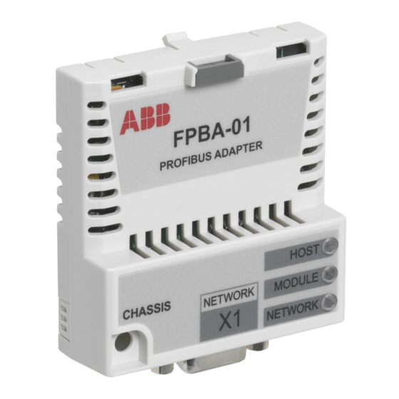
Page 24: Fpba-01 Profibus Dp Adapter Module
24 Overview of the PROFIBUS network and the FPBA-01 module FPBA-01 PROFIBUS DP adapter module The FPBA-01 PROFIBUS DP adapter module is an optional device for ABB drives which enables the connection of the drive to a PROFIBUS network. The drive is considered a slave on the PROFIBUS network. -
Page 25: Layout Of The Adapter Module
Overview of the PROFIBUS network and the FPBA-01 module 25 Layout of the adapter module HOST Diagnostic LEDs NETWORK MODULE (see chapter Diagnostics) NETWORK Bus connector X1 (see chapter Electrical installation) Mounting screw... - Page 26 26 Overview of the PROFIBUS network and the FPBA-01 module...
-
Page 27: What This Chapter Contains
Mechanical installation 27 Mechanical installation What this chapter contains This chapter contains a delivery checklist and instructions on mounting the adapter module. WARNING! Follow the safety instructions given in this manual and the drive documentation. Delivery check The option package for the adapter module contains: •... -
Page 28: Installing The Adapter Module
28 Mechanical installation Installing the adapter module WARNING! Obey the safety instructions. See chapter Safety instructions on page 11. If you ignore the safety instructions, injury or death can occur. The adapter module has a specific position in the drive. Plastic pins, a lock and one screw to hold the adapter module in place. - Page 29 Mechanical installation 29 3. Push in the lock. 4. Tighten the screw to torque 0.8 N·m. Note: It is necessary to tighten the screw properly to fulfill the EMC requirements and to ensure the proper operation of the module. See the applicable drive manual for further instructions on how to install the adapter module to the drive.
- Page 30 30 Mechanical installation...
-
Page 31: What This Chapter Contains
Electrical installation 31 Electrical installation What this chapter contains This chapter contains: • general cabling instructions • instructions on connecting the module to the PROFIBUS DP network • instructions on switching on the bus termination. WARNING! Before installation, switch off the drive power supply. -
Page 32: Connecting The Module To The Profibus Network
32 Electrical installation Connecting the module to the PROFIBUS network Connect the bus cable to connector X1 on the adapter module. The connector pin allocation described below follows the PROFIBUS standard. Description SHLD Alternate cable shield connection. Connected to connector housing. Not used Data positive (Conductor 1 in twisted pair) Request to send... - Page 33 Electrical installation 33 It is recommended to use a PROFIBUS-approved D-SUB 9 connector. These connectors have a built-in termination network and inductors for station capacitance compensation. Connect the cable to the D-SUB connector as follows: 1A 1B 2A 2B Grounding (earthing) clamp/ Strain relief...
-
Page 34: Switching On The Bus Termination
34 Electrical installation Switching on the bus termination Bus termination is required to prevent signal reflections from the bus cable ends. The adapter module is not equipped with internal bus termination. Therefore, the D-SUB connectors at the first and last modules of the bus must have built-on termination switched on as shown in the diagram below. -
Page 35: What This Chapter Contains
Start-up 35 Start-up What this chapter contains This chapter contains: • information on configuring the drive for operation with the adapter module • drive-specific instructions on starting up the drive with the adapter module • examples of configuring the master station for communication with the adapter module. -
Page 36: Drive Configuration
36 Start-up Drive configuration The following information applies to all drive types compatible with the adapter module, unless otherwise stated. PROFIBUS connection configuration After the adapter module is mechanically and electrically installed according to the instructions in chapters Mechanical installation Electrical installation, prepare the drive for communication with the module. -
Page 37: Emulation Modes
Start-up 37 Emulation modes FPBA-01 supports emulation modes for RPBA-01, NPBA-02, NPBA-12 and VIK-NAMUR. Emulation modes change the FPBA-01 identification information so that FPBA-01 accepts connection from PLC configuration made for RPBA-01, NPBA-02, NPBA-12 or VIK-NAMUR. Emulation mode can be used in these conditions: •... - Page 38 38 Start-up FPBA-01 configuration parameters – group A (group 1) Note: The actual parameter group number depends on the drive type. Group A (group 1) corresponds to: • parameter group 51 in ACSM1, ACS355, ACS380, ACS580, ACS850 and ACQ810 • parameter group 51 in ACS880 and ACS880-M04 if the adapter is installed as fieldbus adapter A or group 54 if the adapter is installed as fieldbus adapter B.
- Page 39 Start-up 39 No. Name/Value Description Default 93.75 kbit/s 45.45 kbit/s 19.2 kbit/s 9.6 kbit/s MSG type Read-only. Indicates the telegram 1 = PPO1 type selected for PROFIBUS communication. The adapter module automatically detects the telegram type used. For more information on the supported PPO message types, see section PPO types...
- Page 40 0 = PROFIdrive PROFIdrive profile selected. See also Virtual address allocation with ACSM1 on page 50. 1 = ABB DRIVES ABB Drives profile selected 2 = Trans16 Transparent 16 profile selected 3 = Trans32 Transparent 32 profile selected. Not supported with ACS355.
- Page 41 Start-up 41 No. Name/Value Description Default T16 Scale Defines the reference multiplier/actual value divisor for the adapter module. Note: The parameter is effective only when • Transparent 16 profile is selected • drive is using the native communication profile (for example, DCU or FBA) •...
- Page 42 42 Start-up No. Name/Value Description Default Emul mode Enables the emulation mode for the drive. When the mode is Disabled enabled, it is possible to replace a drive using modules RPBA-01, NPBA-02 or NPBA-12 in the PROFIBUS network with a drive using the FPBA-01 module, without modifying the PLC hardware configuration.
- Page 43 Start-up 43 No. Name/Value Description Default Wrong mapping index (e.g. index MAP_ERR_WRO of PZD 10) is used when PPO NG_IDX type 2 is in use 4 = MAP_ERR_IN Parameter number or virtual index number is not supported for input mapping Parameter number or virtual index MAP_ERR_OUT number is not supported for output...
- Page 44 44 Start-up No. Name/Value Description Default Parameter table revision FBA drive type Read-only. Displays the drive type code code of the fieldbus adapter module mapping file stored in the memory of the drive. Drive type code of the fieldbus adapter module mapping file FBA mapping file Read-only.
- Page 45 Start-up 45 No. Name/Value Description Default FBA A comm SW Read-only. Displays firmware 0 hex patch and build number of the adapter module in format xxyy, where: xx = patch number yy = build number. Example: C80D ≥ 200.13 or 0 ≥ 0.0 0...0xFFFF Firmware patch and build number of the adapter module.
- Page 46 46 Start-up FPBA-01 configuration parameters – group B (group 2) Note: The actual parameter group number depends on the drive type. Group B (group 2) corresponds to: • parameter group 55 in ACS355 • parameter group 53 in ACSM1, ACS380, ACS580, ACS850, ACQ580, and ACQ810 •...
- Page 47 Start-up 47 Name/Value Description Default 13 = Ref2 32bit Reference REF2 (32 bits) 21 = CW2 16bit Control word 2 (16 bits) 101…9999 Parameter index with format xxyy, where • xx is the parameter group number (1…99) • yy is the parameter number index within that group (01…99).
- Page 48 48 Start-up FPBA-01 configuration parameters – group C (group 3) Note: The actual parameter group number depends on the drive type. Group C (group 3) corresponds to: • parameter group 54 in ACS355 • parameter group 52 in ACSM1, ACS380, ACS580, ACS850, ACQ580, and ACQ810 •...
- Page 49 Start-up 49 Name/Value Description Default 24 = SW2 16bit Status word 2 (16 bits) 101…9999 Parameter index with format xxyy, where • xx is the parameter group number (1…99) • yy is the parameter number index within that group (01…99). Other Path to parameter area selection.
-
Page 50: Virtual Address Allocation With Acsm1
50 Start-up Virtual address allocation with ACSM1 When the PROFIdrive profile or PROFIdrive positioning mode is used with an ACSM1 drive, the virtual addresses shown below are recommended. (FBA REFx mode is selected with drive parameter 50.04/50.05.) The information in the table is applicable only if PPO messaging is used (see parameter 04 MSG type). -
Page 51: Control Locations
Start-up 51 Control locations ABB drives can receive control information from multiple sources including digital inputs, analog inputs, the drive control panel and a communication module (for e.g., the adapter module). ABB drives allow the user to separately determine the source for each type of control information (Start, Stop, Direction, Reference, Fault reset, etc.). -
Page 52: Starting Up Acs355 Drives
52 Start-up Starting up ACS355 drives 1. Power up the drive. 2. Enable the communication between the adapter module and the drive by setting parameter 9802 COMM PROT SEL to EXT FBA. 3. Set the FPBA-01 configuration parameters in group 51. At the minimum, set the required node address in parameter 5102 and the communication profile in 5105. -
Page 53: Parameter Setting Examples – Acs355
Start-up 53 Parameter setting examples – ACS355 Speed control using the PROFIdrive communication profile with PPO Type 2 This example shows how to configure a basic speed control application that uses the PROFIdrive profile. In addition, some application-specific data is added to the communication. The start/stop commands and reference are according to the PROFIdrive profile. - Page 54 54 Start-up Drive parameter Setting for Description ACS355 drives 5104 FB PAR 4 2 (= PPO2) Displays the telegram type (TELEGRAM TYPE) selected by the PLC configuration tool. 5105 FB PAR 5 0 (= PROFIdrive) Selects the Control word (PROFILE) according to the PROFIdrive profile (speed control mode).
-
Page 55: Cation Profile With Ppo Type 4
PPO Type 4 This example shows how to configure a speed and torque control application that uses the ABB Drives profile. From the PLC programming point, the ABB Drives profile is similar to the PROFIdrive profile shown in the first example. - Page 56 (TELEGRAM TYPE) selected by the PLC configuration tool. 5105 FB PAR 5 1 (= ABB Selects the Control word (PROFILE) DRIVES) according to the ABB Drives profile. 3018 COMM FAULT 3 = LAST Enables fieldbus FUNC SPEED communication fault monitoring.
- Page 57 Start-up 57 Drive parameter Setting for Description ACS355 drives 5402 FBA DATA IN 2 5 (= Act1 16bit) Actual value 1 (speed) 5403 FBA DATA IN 3 6 (= Act2 16bit) Actual value 2 (torque) 5501 FBA DATA OUT 1 1 (= CW 16bit) Control word 5502 FBA DATA OUT 2...
- Page 58 58 Start-up Drive parameter Setting for Description ACS355 drives 1604 FAULT RESET SEL 8 = COMM Selects the fieldbus interface as the source for the fault reset signal. Read-only or automatically detected/set Example The start sequence for the parameter example above is given below.
-
Page 59: Starting Up Acsm1 Drives
Start-up 59 Starting up ACSM1 drives 1. Power up the drive. 2. Enable the communication between the adapter module and the drive by setting parameter 50.01 FBA ENABLE to Enable. 3. With parameter 50.02 COMM LOSS FUNC, select how the drive reacts to a fieldbus communication break. -
Page 60: Parameter Setting Examples – Acsm1
60 Start-up Parameter setting examples – ACSM1 Speed control using the PROFIdrive communication profile with PPO Type 2 This example shows how to configure a basic speed control application that uses the PROFIdrive profile. In addition, some application-specific data is added to the communication. The start/stop commands and reference are according to the PROFIdrive profile, speed control mode. - Page 61 Start-up 61 Drive parameter Setting for Description ACSM1 drives 51.02 FBA PAR2 Defines the PROFIBUS (NODE ADDRESS) node address of the fieldbus adapter module. 51.03 FBA PAR3 12000 Displays the current baud (BAUD RATE) rate on the PROFIBUS network in kbit/s. 51.04 FBA PAR4 2 (= PPO2) Displays the telegram type...
-
Page 62: File With Ppo Type 4
62 Start-up Drive parameter Setting for Description ACSM1 drives 24.01 SPEED REF1 FBA REF1 Selects the fieldbus reference 1 as the source for speed reference 1. 34.03 EXT1 CTRL Speed Selects speed control as MODE1 the control mode 1 for external control location 1. - Page 63 Start-up 63 The table below gives the recommended drive parameter settings. Drive parameter Setting for Description ACSM1 drives 50.01 FBA ENABLE Enable Enables communication between the drive and the fieldbus adapter module. 50.02 COMM LOSS Fault Enables fieldbus FUNC communication fault monitoring.
- Page 64 64 Start-up Drive parameter Setting for Description ACSM1 drives 53.02 FBA DATA OUT2 12 (= Ref1 32bit) Reference 1 53.04 FBA DATA OUT4 13 (= Ref2 32bit) Reference 2 51.27 FBA PAR REFRESH Validates the FPBA-01 REFRESH configuration parameter settings. 10.01 EXT1 START Selects the fieldbus FUNC...
- Page 65 Start-up 65 Drive parameter Setting for Description ACSM1 drives 65.03 POS START 1 C.False Selects the fieldbus as the position start1 source. 65.04 POS REF 1 SEL FBA REF 1 Selects the FBA reference 1 as the position reference source. 65.11 POS START 2 C.False Selects the fieldbus as the...
- Page 66 66 Start-up The position set point and actual values are scaled with the above example values as follows: 1000 / 100 = 10.00 60.05 POS UNIT Physical value 60.08 POS2INT SCALE Set point value Example for velocity set point scale: Drive parameter Value Description 60.10 POS SPEED UNIT...
-
Page 67: Cation Profile With Ppo Type 4
PPO Type 4 This example shows how to configure a speed and torque control application that uses the ABB Drives profile. From the PLC programming point, the ABB Drives profile is similar to the PROFIdrive profile shown in the first example. - Page 68 51.05 FBA PAR5 1 (= ABB Selects the Control word (PROFILE) DRIVES) according to the ABB Drives profile. 52.01 FBA DATA IN1 4 (= SW 16bit) Status word (PZD 1) 52.02 FBA DATA IN2 5 (= Act1 16bit) Actual value 1 52.03 FBA DATA IN3...
- Page 69 Start-up 69 Drive parameter Setting for Description ACSM1 drives 53.02 FBA DATA 2 (= Ref1 16bit Reference 1 OUT2 53.03 FBA DATA 3 (= Ref2 16bit Reference 2 OUT3 51.27 FBA PAR REFRESH Validates the FPBA-01 REFRESH configuration parameter settings. 10.01 EXT1 START Selects the fieldbus interface FUNC...
- Page 70 70 Start-up The start sequence for the parameter example above is given below. Control word Start sequence 47Eh (1150 decimal) READY TO SWITCH ON 47Fh (1151 decimal) OPERATING (Speed mode) C7Fh (3199 decimal) OPERATING (Torque mode)
-
Page 71: Starting Up Acs380 Drives
50.01 FB A enable Enable 50.02 FB A comm loss func Fault 51.02 Node address 51.05 Profile ABB Drives 52.01 FBA A data in1 SW 16 bit 52.02 FBA A data in 2 Act1 16 bit 53.01 FBA A data out1 CW 16 bit 53.02 FBA A data out2... -
Page 72: Setting Up The Drive For Fieldbus Control Manually
72 Start-up The start sequence for the parameter example above is given below. Control word Start sequence 47Eh (1150 decimal) READY TO SWITCH ON 47Fh (1151 decimal) OPERATING (Speed mode) Setting up the drive for fieldbus control manually The fieldbus adapter module is typically pre-installed. The device automatically recognizes the module. - Page 73 Start-up 73 9. Save the valid parameter values to permanent memory by setting parameter 96.07 Parameter save manually to Save. 10. Validate the settings made in parameter groups 51, 52 and 53 by setting parameter 51.27 FBA A par refresh to Configure. 11.
-
Page 74: Starting Up Acs850 And Acq810 Drives
74 Start-up Starting up ACS850 and ACQ810 drives 1. Power up the drive. 2. Enable the communication between the adapter module and the drive by setting parameter 50.01 FBA enable to Enable. 3. With parameter 50.02 Comm loss func, select how the drive reacts to a fieldbus communication break. -
Page 75: Parameter Setting Examples – Acs850 And Acq810
Start-up 75 Parameter setting examples – ACS850 and ACQ810 Speed control using the PROFIdrive communication profile with PPO Type 2 This example shows how to configure a basic speed control application that uses the PROFIdrive profile. In addition, some application-specific data is added to the communication. - Page 76 76 Start-up Drive parameter Setting for Description ACS850/ ACQ810 drives (ACQ810 only) bit 0 = 1 Enables communication loss 50.21 Comm loss detection for EXT 1. enable 51.01 FBA type Profibus-DP Displays the type of the fieldbus adapter module. 51.02 FBA par2 Defines the PROFIBUS node (NODE ADDRESS) address of the fieldbus adapter...
- Page 77 Start-up 77 Drive parameter Setting for Description ACS850/ ACQ810 drives 10.01 Ext1 start func Selects the fieldbus interface as the source of the start and stop commands for external control location 1. 10.08 FAULT RESET P.FBA MAIN Selects fieldbus interface as CW.8 the source for fault reset.
-
Page 78: Starting Up Acs880 And Acs880-M04 Drives
78 Start-up Starting up ACS880 and ACS880-M04 drives 1. Power up the drive. 2. Enable communication between the adapter module and the drive by setting parameter 50.01 FBA A Enable, option slot 1, 2 or 3 depending on the slot the adapter module is attached to. 3. -
Page 79: Parameter Setting Examples – Acs880 And Acs880-M04
Start-up 79 10. Set the relevant drive control parameters to control the drive according to the application. Examples of appropriate values are shown in the tables below. Parameter setting examples – ACS880 and ACS880- Speed control using the PROFIdrive communication profile with PPO Type 2 This example shows how to configure a basic speed control application that uses the PROFIdrive profile. - Page 80 80 Start-up Drive parameter Setting for Description ACS880 drives 51.01 FBA A type 1 = FPBA Displays the type of the fieldbus adapter module. 51.02 FBA A Par2 Defines the PROFIBUS node address of the fieldbus adapter module. 51.03 Baud rate 12000 Displays the current baud rate on the PROFIBUS...
- Page 81 Start-up 81 Drive parameter Setting for Description ACS880 drives 20.01 Ext1 commands 12 = Fieldbus A Selects the fieldbus A interface as the source of the start and stop commands for external control location 1. 20.02 Ext1 start trigger 1 = Level Selects the start trigger type type to be level.
-
Page 82: Configuring The Master Station
After the adapter module is initialized by the drive, prepare the master station for communication with the module. See examples of an ABB AC500 PLC and Siemens SIMATIC S7 PLC given below. If you are using another master system, refer to its documentation for more information. -
Page 83: Configuring An Abb Ac500 Plc
Configuring an ABB AC500 PLC This example shows how to configure the communication between an ABB AC500 PLC and the adapter module using the Automation Builder software, version 1.2 and later. Before you start, make sure that you have downloaded the FPBA- 01 GSD file from the Document library. - Page 84 84 Start-up 7. Add the DP module, for example, PPO Type 4 to the FPBA-01 module to define cyclical communication between the adapter module and the PLC. 8. Define the CM572-DP master properties, such as the Baud rate, Node address (Station address) and the Highest station address.
- Page 85 Start-up 85 9. Define the FPBA-01 properties: On the DP-Parameters tab, • select the Node address (Station address) and the DP Mode • configure the Fail-safe functionality.
- Page 86 86 Start-up 10. Define the DP module properties: On the DP-module I/O Mapping tab, type names for the variables that refer to the drive's signals in the PLC program. 11. Open the PLC program and create a program that controls the drive.
- Page 87 Start-up 87 12. Compile the project and download it to the PLC. Note: Make sure that the variable names defined for the drive signals are used in the PLC program. Otherwise the communication will not work.
-
Page 88: Configuring A Siemens Simatic S7 Plc
88 Start-up Configuring a Siemens SIMATIC S7 PLC This example shows how to configure the communication between a Siemens SIMATIC S7 PLC and the adapter module using SIMATIC Manager Step 7. Before you start, make sure that you have downloaded the FPBA- 01 GSD files from the Document library. - Page 89 Start-up 89 • Choose the GSD file based on the software version of the module (see underside of the module) and what DP extension version will be used. 5. Click and drag the FPBA-01 object from the device catalog to the PROFIBUS(1): DP master system(1).
- Page 90 90 Start-up 6. Click and drag the PP0 Type 7 object to slot 1. Then double- click FPBA. The Properties window appears. 7. On the General tab, click PROFIBUS... and set Node number.
- Page 91 Start-up 91 8. Click Properties → Network Settings and set baud rate.
- Page 92 92 Start-up 9. Open the Parameter Assignment tab. • Under the Device-specific parameters folder configure the Fail Safe mode and Control-zero mode. • Enter a Failsafe Timeout value. • Configure Failsafe values for the PLC output process data (PZDs).
- Page 93 Start-up 93 10. Save and compile the hardware configuration. 11. Download the compiled hardware configuration to the PLC. The PLC is now ready for communication with the adapter module. 12. If needed, give proper symbol names to the cyclic data: •...
-
Page 94: Configuring A Siemens S7 Plc With Tia Portal V13
94 Start-up Configuring a Siemens S7 PLC with TIA Portal V13 This example shows how to configure the communication between a Siemens SIMATIC S7 PLC and the adapter module using TIA Portal V13. Before you start, make sure that you have downloaded the FPBA- 01 GSD files from the Document library. - Page 95 Start-up 95 5. In TIA portal, go to Network view. Drag and drop FPBA-01 from the Device catalog to the Network view. 6. Click on Not assigned text and select the master to create link between the master and FPBA-01. 7.
- Page 96 96 Start-up 8. In the General tab, set FPBA-01 node address. 9. In the Device-specific parameters, set fail-safe mode, time out and fail-safe values. 10. Compile and download the project. After the PLC starts, node 3 (FPBA-01) goes online with PPO-...
-
Page 97: Cyclic Data Handling
Start-up 97 Cyclic data handling With FPBA-01, both data-consistent and non-consistent communication can be used, data-consistent meaning that the whole cyclic data frame is transmitted during a single program cycle. Some PLCs handle this internally, but others must be programmed to transmit data-consistent telegrams. - Page 98 98 Start-up...
-
Page 99: What This Chapter Contains
With the FPBA-01 module, the PROFIBUS network may employ either the PROFIdrive profile or the ABB Drives profile. Both are converted to the native profile (e.g., DCU or FBA) by the adapter module. In addition, two Transparent modes – for 16-bit and 32-bit words respectively –... - Page 100 (ST) are used, the communication profile is selected automatically. The following sections describe the Control word, the Status word, references and actual values for the PROFIdrive and ABB Drives communication profiles. Refer to the drive manuals for details on the native profiles.
-
Page 101: Profidrive Communication Profile
Communication profiles 101 PROFIdrive communication profile Control word and Status word The Control word (PROFIdrive parameter 967) is the principal means for controlling the drive from a fieldbus system. It is sent by the fieldbus master station to the drive through the adapter module. - Page 102 102 Communication profiles Name Value STATE/Description Speed control Positioning mode mode OFF3 Continue operation (OFF3 inactive). Emergency stop, stop according to fastest possible deceleration mode. Proceed to OFF3 ACTIVE; proceed further to SWITCH-ON INHIBIT. Warning: Ensure motor and driven machine can be stopped using this stop mode.
- Page 103 Communication profiles 103 Name Value STATE/Description Speed control Positioning mode mode Normal operation. Activate traversing task (0 → 1). This is Proceed to OPERATING. a toggle bit; each rising edge of signal Note: This bit is enables a traversing effective only if the task or a new set fieldbus interface is point.
- Page 104 104 Communication profiles Name Value STATE/Description Speed control Positioning mode mode Vendor-specific bit as defined by PROFIdrive parameter 936 Vendor-specific bit as defined by PROFIdrive parameter 937...
-
Page 105: Status Word Contents
Communication profiles 105 Status word contents The table below shows the contents of the Status word for the PROFIdrive communication profile (PROFIdrive parameter 968). The upper case boldface text refers to the states shown in the state machine on page 107. Name Value STATE/Description Speed control... - Page 106 106 Communication profiles Name Value STATE/Description Speed control Positioning mode mode Actual frequency or Target position speed value equals reached or is greater than supervision limit. Actual frequency or Not at target speed value is position within supervision limit. Vendor-specific bit Homing procedure as defined by was executed and is...
-
Page 107: State Machine For All Operating Modes
Communication profiles 107 State machine for all operating modes The general PROFIdrive state machine for all operating modes is shown below. SWITCH-ON PROFIdrive MAINS OFF INHIBIT (SW Bit6=1) State machine OFF1 (CW Bit0=0) Power ON CW = Control NOT READY word TO SWITCH ON (SW Bit0=0) -
Page 108: State Machine For Positioning Mode
108 Communication profiles State machine for positioning mode The PROFIdrive state machine for the positioning mode is shown below. BASIC STATE: (SW Bit10,13=1) Operating (CW Bit4,5=1 (CW Bit11=1) CW Bit6 edge 01) HOMING RUNNING Bit10,11,13=0) HOMING READY Bit10,11,13=1) (CW Bit11=0) Traversing PROFIdrive (SW Bit10,13=0) -
Page 109: References
Communication profiles 109 References ABB drives can receive control information from multiple sources including analog and digital inputs, the drive control panel and a communication module (for example, FPBA-01). In order to have the drive controlled through PROFIBUS, the communication module must be defined as the source for control information, for example, reference. -
Page 110: Actual Values
110 Communication profiles Actual values Actual values are 16-bit or 32-bit words containing information on the operation of the drive. The functions to be monitored are selected with a drive parameter. Actual values in speed control mode The scaling of 16-bit actual speed values (ACT or NIST_A) in hexadecimal (0…4000h) corresponds to 0…100% of speed scaling value (as defined with a drive parameter). -
Page 111: Abb Drives Communication Profile
The drive states are presented on page 115. Control word contents The table below shows the contents of the Control word for the ABB Drives communication profile. The upper case boldface text refers to the states shown on page 115. Name... - Page 112 112 Communication profiles Name Value STATE/Description INHIBIT_ Proceed to OPERATION ENABLED. OPERATION Note: Run enable signal must be active; see drive documentation. If the drive is set to receive the Run enable signal from the fieldbus, this bit activates the signal. Inhibit operation.
-
Page 113: Status Word Contents
12… Drive-specific (For information, see the drive documentation.) Status word contents The table below shows the contents of the Status word for the ABB Drives communication profile. The upper case boldface text refers to the states shown on page 115. - Page 114 114 Communication profiles Name Value STATE/Description ALARM Warning/alarm No warning/alarm AT_SETPOINT OPERATION. Actual value equals reference value (= is within tolerance limits, i.e., in speed control, speed error is 10% maximum of the nominal motor speed). Note that tolerance limit can be configured in the drive side, for example, speed window in this case.
-
Page 115: State Machine
Communication profiles 115 State machine The state machine for the ABB Drives communication profile is shown below. SWITCH-ON ABB Drives MAINS OFF INHIBITED (SW Bit6=1) communication Power ON (CW Bit0=0) profile NOT READY TO CW = Control SWITCH ON A B C D... -
Page 116: References
ABB drives can receive control information from multiple sources including analog and digital inputs, the drive control panel and a communication module (for example, FPBA-01). In order to have... -
Page 117: Actual Values
Communication profiles 117 Actual values Actual values are 16-bit words containing information on the operation of the drive. The functions to be monitored are selected with a drive parameter. Scaling Actual values are scaled as shown below. Note: The values of REF1 MAX and REF2 MAX are set with drive parameters. - Page 118 118 Communication profiles...
-
Page 119: What This Chapter Contains
Communication protocol 119 Communication protocol What this chapter contains This chapter describes the PROFIBUS messaging used in the communication with the drive and in PROFIBUS slave device configuration messages. PROFIBUS DP The FPBA-01 module supports the PROFIBUS DP-V0 and DP-V1 protocols according to the IEC 61158, IEC 61784 and EN 50170 standards. -
Page 120: Service Access Points (Saps)
120 Communication protocol Service access points (SAPs) The services of the PROFIBUS Data Link Layer (Layer 2) are used by PROFIBUS DP through service access points (SAPs). Precisely defined functions are assigned to individual SAPs. For further information on SAPs, refer to the manual of the PROFIBUS master, PROFIDRIVE –... -
Page 121: Profibus Sd2 Telegram For Default Sap (0) And Sap
Communication protocol 121 PROFIBUS SD2 telegram for Default SAP (0) and SAP 58-62 PROFIBUS typically uses SD2 telegrams for DP communication. The structure of an SD2 telegram is shown below. DP header DP trailer LEr SD DA SA *DSAP *SSAP DU FCS 68h x 68h xx x…... -
Page 122: Sap 58 (Global_Control)
122 Communication protocol For more information, see section PROFIBUS SD2 telegram for Default SAP (0) and SAP 58-62 on page 121. SAP 58 (Global_Control) This SAP is used to send special commands addressed to a single slave, a special group of slaves, or all slaves at once (broadcast). Global_Control Type: Octet String - Length: 2 DU Byte... -
Page 123: Sap 60 (Slave_Diag)
Communication protocol 123 SAP 60 (Slave_Diag) This SAP gives diagnostic information on the slave station. Diag_Data (Diagnostic Data) Type: Octet String - Length: 6 (Standard) + 2 (Extended Diagnosis) (DP-V0 mode) + 5 (Extended Diagnosis) (DP-V1 mode) Note: During initialization, the module only sends the standard part of the message. - Page 124 124 Communication protocol Station_Status_2 Diag.Prm_Req (Set by Slave) Slave requires re-configuration and re-parameterization Diag.Stat_Diag (Set by Slave) Static diagnosis. Slave (temporarily) unable to provide valid data. Always set to 1 by slave Diag.WD_On (Set by Slave) Watchdog on Diag.Freeze_Mode (Set by Slave) Freeze command received by slave Diag.Sync_Mode (Set by Slave) Sync command received by...
- Page 125 Communication protocol 125 Header Byte (DP-V1 only) The complete header consists of 5 bytes with FPBA-01. Block length in bytes including header Diagnostic type 00 = Device-related diagnostic according to PROFIdrive 3.1. Communication Diagnostic (DP-V0 only) 0 0 0 0 0 0 Communication temporarily lost Communication permanently...
- Page 126 126 Communication protocol Specifier (0x00) (DP-V1 only) 0 0 0 0 0 0 Specifier Reserved Communication Diagnostic (DP-V1 only) 0 0 0 0 0 0 x Communication temporarily lost Communication permanently lost Reserved The FPBA-01 module is operated in the DP-V1 mode. The diagnostic information is according to PROFIdrive 3.1.
-
Page 127: Sap 61 (Set_Prm)
Communication protocol 127 SAP 61 (Set_Prm) This SAP is used in the parameterization of the drive. Prm_Data (Parameter Data Standard) Type: Octet String Total length: 37 – Prm_Data length: 14 – User_Prm_Data length: 23 Value Description Byte Station status (Recom- x x 1 1 1 0 0 0 mended default... - Page 128 128 Communication protocol DPV1_Status_1 (DP-V1 only) x 0 x 0 0 x x x Dis_Start_Control (Disable Stop-Bit Control) 0 = Start bit monitoring in receiver enabled 1 = Start bit monitoring in receiver disabled Dis_Stop_Control (Disable Stop-Bit Control) 0 = Stop bit monitoring in receiver enabled 1 = Stop bit monitoring in receiver disabled...
- Page 129 Communication protocol 129 DPV1_Status_2 (DP-V1 only) (Not supported) x x x x x x 0 x Chk_Cfg_Mode 0 = Chk_Cfg according to EN 50170 (default state) 1 = User-specific evaluation of Chk_Cfg Reserved. To be parameterized with ‘0’. Enable_Update_Alarm 0 = Enable_Update_Alarm disabled 1 = Enable_Update_Alarm enabled...
- Page 130 130 Communication protocol DPV1_Status_3 (DP-V1 only) 0 0 0 x 1 x x x Alarm_Mode. Not supported. Limits the number of active alarms. 0 = 1 alarm of each type 1 = 2 alarms in total 2 = 4 alarms in total 3 = 8 alarms in total 4 = 12 alarms in total 5 = 16 alarms in total...
- Page 131 Communication protocol 131 User_Prm_Data (Parameter Data Extended) Type: Octet String - Length: 23 Header byte (Default) 0 0 0 0 0 x 0 x Fail-safe mode. Defines the action taken when the PLC is switched from ‘RUN’ to ‘STOP’ mode. 00 = STOP (default) 01 = LAST REFERENCE 02 = USE FAIL-SAFE.
-
Page 132: Sap 62 (Chk_Cfg)
132 Communication protocol 21… 0… Fail-safe, PZD3 65536 23… 0… Fail-safe, PZD4 65536 25… 0… Fail-safe, PZD5 65536 27… 0… Fail-safe, PZD6 65536 29… 0… Fail-safe, PZD7 65536 31… 0… Fail-safe, PZD8 65536 33… 0… Fail-safe, PZD9 65536 35… 0… Fail-safe, PZD10 65536 The extended parameter data bytes are configured through the... - Page 133 Communication protocol 133 Telegram Cyclical telegram Default code for Supported name length (in words) message type parameter channel access (see figure below) mode PPO 5 4 PKW + 10 PZD F3 F9 DP-V0 / DP-V1 in/out PPO 6 0 PKW + 10 PZD DP-V1 in/out PPO 7...
-
Page 134: Other Saps For Dp-V1 Communication
134 Communication protocol The default codes for the PPO types in the table above define data consistency over the message as follows: x x x x x x x x Length of data 0000 = 1 byte per word • • • 1111 = 16 bytes per word Input/Output 00 = Special format... -
Page 135: Cyclical Message Types
Communication protocol 135 Cyclical message types PPO types Process data Parameter Fixed area Freely mappable area identification OUT area PZD12 VALUE CW REF PZD3 PZD4 PZD5 PZD8 PZD9 PZD10 PZD11 PZD6 PZD7 IN area PZD12 PZD3 PZD4 PZD5 PZD6 PZD7 PZD8 PZD9 PZD10 PZD11 VALUE... -
Page 136: Standard Telegram (St) Types (Dp-V1)
136 Communication protocol Standard telegram (ST) types (DP-V1) PZD1 PZD2 OUT area STW1 NSOLL_A Control word 1 Speed set point A IN area ZSW1 NIST_A Status word 1 Speed actual value A PZD1 PZD2…3 PZD4 OUT area STW1 NSOLL_B STW2 Control word 1 Speed set point B... -
Page 137: Parameter Handling In Cyclic Communication (Dp)
Communication protocol 137 Parameter handling in cyclic communication (DP) In cyclic PROFIBUS DP communication, parameter data is transferred in PPO message types 1, 2 and 5, as shown in section PPO types on page 135. The parameter identification part consists of eight bytes, as shown below. - Page 138 138 Communication protocol Request labels (from master to slave) Request Function Response labels Ackn. (+) Ackn. (-) Change parameter value (array 7, 8 word) Change parameter value (array 7, 8 double word) Request number of array elements Response label (Acknowledgement from slave to master) Ackn.
- Page 139 Communication protocol 139 Response label (Acknowledgement from slave to master) Ackn. Function Task cannot be executed, followed by error number = Illegal parameter number = Parameter value cannot be changed = Lower or upper limit violated = Erroneous subindex = No array = Incorrect data type = Setting not allowed (can only be reset) = Descriptive element cannot be changed...
- Page 140 140 Communication protocol The allocation of drive control/actual words, drive parameters and PROFIdrive parameters to the parameter identification part of the PPO type is shown below. • The Index column corresponds to the parameter number (PNU) in the ID part of parameter identification. •...
-
Page 141: Profidrive Parameters
Communication protocol 141 PROFIdrive parameters Index Sub-index Par. No Request label Example (Decimal) 393h • • • • • • 394h • • • • • • 396h 3, 4 • • • 3B3h • • • 3CCh 3, 4 For a complete PROFIdrive parameter list, see Appendix A –... -
Page 142: Parameter Data Transfer Examples (Dp-V0)
142 Communication protocol Parameter data transfer examples (DP-V0) Note: Only the ‘data unit’ part of the telegram is presented in the examples. See section PROFIBUS SD2 telegram for Default SAP (0) and SAP 58-62 on page 121. Example 1: Reading a drive parameter (or data set) To determine the parameter number and subindex for drive parameter reading, convert the drive parameter group number and the parameter index number to hexadecimal. - Page 143 Communication protocol 143 Error response Resp PZD3 PZD4 PZD5 PZD6 Error Number (3: Erroneous subindex) Subindex Parameter Number Response (Negative acknowledgement) 2nd byte reserved...
-
Page 144: Example 2: Writing A Drive Parameter (Or Data Set)
144 Communication protocol Example 2: Writing a drive parameter (or data set) To determine the parameter number and subindex for drive parameter writing, convert the drive parameter group number and the parameter index number to hexadecimal. The index number is the Subindex (IND), and the group number is the Parameter Number (PNU). - Page 145 Communication protocol 145 The following is an example of writing a 32-bit parameter: Request (Change parameter value [array double word]) Parameter Number Subindex Parameter Value (100 decimal) PZD3 PZD4 PZD5 PZD6 Resp PZD3 PZD4 PZD5 PZD6 Parameter Value (100 decimal) Subindex Parameter Number Response (Transfer parameter value [array double word])
-
Page 146: Example 3: Reading A Profidrive Parameter (Word)
146 Communication protocol Example 3: Reading a PROFIdrive parameter (word) In this example, PROFIdrive parameter 918 is used to read the station number of the slave. Request (Parameter value read) Parameter Number (918 decimal) Param.Value Read: Req header trailer Resp Param.Value Parameter Number (918 decimal) Request (Parameter value updated) -
Page 147: Example 4: Writing A Profidrive Parameter (Word)
Communication protocol 147 Example 4: Writing a PROFIdrive parameter (word) In this example, current parameter settings are saved to the FLASH memory of the drive. This is done by setting the value of PROFIdrive parameter 971 (3CBh) to 1. Note that the drive always observes the Control word (CW) and reference (REF) bytes. -
Page 148: Example 5: Reading A Profidrive Parameter (Array)
148 Communication protocol Example 5: Reading a PROFIdrive parameter (array) In this example, PROFIdrive parameter 945 is used to read the code of the active fault. As shown on page 187, parameter 945 is of the array type with subindexes 0 and 1. Request (Request parameter value [array]) Parameter Number (945 decimal) Subindex (Latest acknowledged fault) -
Page 149: Drive
Communication protocol 149 Example 6: Configuring the process data written to the drive PROFIdrive parameter 915 can be used to define which data is written cyclically to a drive parameter as application-specific process data. In the example below, the value of drive parameter 12.02 (0Ch.02h) is selected to be taken from PZD3. -
Page 150: Drive
150 Communication protocol Example 7: Configuring the process data read from the drive PROFIdrive parameter 916 can be used to define which data is read cyclically from the drive as application-specific process data. In the example below, drive parameter 1.04 (01h.04h) is selected to be transmitted by the drive as PZD3. -
Page 151: Dp-V1 Read/Write Request Sequence
Communication protocol 151 Subsequent response frames: Resp PZD3 (Value of drive parameter 1.04) DP-V1 read/write request sequence A read/write service on a drive parameter is illustrated below. Master DP-V1 Slave PROFIdrive Write request DB47 Parameter request Parameter request Write response without data Read request DB47 without data... - Page 152 152 Communication protocol performing the internal parameter request, it will return a negative response with the DP-V1 error code B5h (State conflict). In this case, the read request will be repeated by the master until the adapter module has the PROFIdrive response data ready. If the write request is invalid, a negative response is returned with a DP-V1 error code (see page 155).
-
Page 153: Profibus Sd2 Telegram For Sap 51
Communication protocol 153 PROFIBUS SD2 telegram for SAP 51 The read/write service uses a variable-length PROFIBUS SD2 telegram shown below. DP header DP trailer LEr SD DSAP SSAP DU FCS 68h x 68h xx x… xx SD = Start delimiter LE = Length LEr = Length repeated DA = Destination address... - Page 154 154 Communication protocol The table below lists the DP-V1 function numbers. Value Meaning 0x48 Idle REQ, RES 0x51 Data transport REQ, RES 0x56 Resource manager REQ 0x57 Initiate REQ, RES 0x58 Abort REQ 0x5C Alarm REQ, RES 0x5E Read REQ, RES 0x5F Write REQ, RES 0xD1...
- Page 155 Communication protocol 155 The table below lists the error codes for the DP-V1 error responses. Error class Meaning Error code 0…9 (Reserved) 10 (0x0A) Application 0 = Read error 1 = Write error 2 = Module failure 3…7 = Reserved 8 = Version conflict 9 = Feature not supported 10…15 = User-specific...
- Page 156 156 Communication protocol The table below shows the contents of the PROFIdrive Request header. Field(s) Description Range Byte/Word Request Unique identification 1…255 Byte Reference set by the master. Changed for each new request. Request ID Request type for the Request Byte issued block Parameter (01h)
- Page 157 Communication protocol 157 Field(s) Description Range Byte/Word Subindex Addresses 0…65535 Word • the first array element of the parameter or • the beginning of a string access or • the text array or • the description element that is being accessed. Format See the table on page See the table on...
- Page 158 158 Communication protocol The table below shows the contents of the PROFIdrive Response header. Field(s) Description Range Request Mirrored from the request 1…255 Reference (mirrored) Response ID Response from the slave. In Request Param OK case any requested services fail, (01h) a “not acknowledged”...
- Page 159 Communication protocol 159 The table below shows the data types for the Format field. Code Type 0x00 (Reserved) 0x01…0x36 Standard data types Boolean (not supported) Integer8 (not supported) Integer16 Integer32 Unsigned8 (not supported) Unsigned16 Unsigned32 Floating point (not supported) Visible string (not supported) •...
- Page 160 160 Communication protocol The table below shows the PROFIdrive parameter request error codes Error # Meaning Used at Impermissible Access to an unavailable parameter parameter number Parameter value cannot Change access to a parameter be changed value that cannot be changed Low or high limit Change access with a value outside exceeded...
- Page 161 Communication protocol 161 Error # Meaning Used at Response too long The length of the current response exceeds the maximum transmittable length. Parameter address Illegal value or value that is not impermissible supported for the attribute, number of elements, parameter number or sub-index, or a combination Illegal format Write request: Illegal format or...
-
Page 162: Parameter Data Transfer Examples (Dp-V1)
162 Communication protocol Error # Meaning Used at Illegal Request ID The request ID of the response is illegal. Internal buffer Buffer overflow Internal communication Communication error between the module and the drive Parameter data transfer examples (DP-V1) The following examples show how parameter data is transferred using the DP-V1 mechanisms READ and WRITE. - Page 163 Communication protocol 163 • Positive Read response to DP-V1 Read request: Function number Slot number Index Data length Response reference (mirrored) Response ID Drive object ID Number of parameters Format (42h = Word) Number of values Parameter value 5E 01 2F 08 05 01 01 01 42 01 05 64 DP header trailer DP-V1...
- Page 164 164 Communication protocol Example 1b: Reading 3 drive parameters (multi-parameter) In this example, three parameters (12.04, 20.08 and 30.19) are read using one telegram. • DP-V1 Write request (Read parameter value): Function number Slot number Index Data length Request reference Request ID (01h= Request Parameter Drive object ID Number of parameters...
- Page 165 Communication protocol 165 • Positive Read response to DP-V1 Read request: Function number Slot number Index Data length Response reference (mirrored) Response ID Drive object ID Number of parameters Format (42h = Word) Number of values Parameter value 01 0 •••...
-
Page 166: Example 2A: Writing A Drive Parameter (One Array Element
166 Communication protocol Example 2a: Writing a drive parameter (one array element) Drive parameters are addressed so that the drive parameter group corresponds to the Parameter index (PNU), and the drive parameter number within that group corresponds to the Subindex (IND). - Page 167 Communication protocol 167 Slot number Slot number Index Data length Request reference (mirrored) Response ID Drive object ID (mirrored) Number of parameters 5E 01 2F 04 header trailer DP-V1 Response PROFIdrive V3 Parameter Channel...
-
Page 168: Example 2B: Writing 2 Drive Parameters (Multi-Parameter
168 Communication protocol Example 2b: Writing 2 drive parameters (multi-parameter) In this example, the values 300 (12Ch) and 500 (1F4h) are written to drive parameters 12.02 (0C.02h) and 20.08 (14.08h) respectively using one telegram. Function number Slot number Index Data length Request reference Request ID (02h= Change Parameter) Drive object ID... - Page 169 Communication protocol 169 Slot number Slot number Index Data length Request reference (mirrored) Response ID Drive object ID (mirrored) Number of parameters 5E 01 2F 04 header trailer DP-V1 Response PROFIdrive V3 Parameter Channel...
-
Page 170: Example 3: Reading A Profidrive Parameter
170 Communication protocol Example 3: Reading a PROFIdrive parameter In this example, PROFIdrive parameter 918 (396h) is used to read the station number of the slave. • DP-V1 Write request (Reading a PROFIdrive parameter): Function number Slot number Index Data length Request reference Request ID (01h= Request Parameter) Drive object ID... -
Page 171: Drive
Communication protocol 171 Example 4: Configuring the process data written to the drive PROFIdrive parameter 915 (393h) can be used to define which data is written cyclically to a drive parameter as application-specific process data. In the example below, the value of drive parameter 12.06 (0C.06h) is selected to be taken from PZD3. - Page 172 172 Communication protocol • DP-V1 Read response: Function number Slot number Index Data length Request reference (mirrored) Response ID Drive object ID (mirrored) Number of parameters Format (42h = Word) Number of values Value 5E 01 2F 08 0A 01 01 01 42 01 00 68 DP header trailer DP-V1...
-
Page 173: From The Drive
Communication protocol 173 Example 5: Determining the source of process data read from the drive PROFIdrive parameter 916 (394h) can be used to define which data is read cyclically from the drive as application-specific process data. In the example below, the parameter is used to determine which drive parameter the contents of PZD3 are taken from. - Page 174 174 Communication protocol • DP-V1 Read response: Function number Slot number Index Data length Request reference (mirrored) Response ID Drive object ID (mirrored) Number of parameters Format (42h = Word) Number of values Value 5E 01 2F 08 0B 01 01 01 42 01 0C 05 DP header trailer DP-V1...
-
Page 175: What This Chapter Contains
Diagnostics 175 Diagnostics What this chapter contains This chapter explains how to trace faults with the status LEDs on the adapter module. -
Page 176: Led Indications
Establishing communication to host, or communication to host lost HOST Flashing orange, Internal file system error. The alternating with the error may be cleared by MODULE flashing orange cycling drive power. If the error persists, contact your local ABB representative. - Page 177 Flashing orange, Internal file system error. The alternating with the HOST error may be cleared by flashing orange cycling drive power. If the error persists, contact your local ABB representative. Blinking green Establishing network connection NETWORK Green Network connection OK...
- Page 178 178 Diagnostics...
-
Page 179: What This Chapter Contains
Technical data 179 Technical data What this chapter contains This chapter contains the technical data of the adapter module and the PROFIBUS link. FPBA-01 Enclosure: HOST MODULE NETWORK NETWORK... - Page 180 180 Technical data Mounting: Into the option slot on the drive Degree of protection: IP20 Ambient conditions: The applicable ambient conditions specified for the drive in its manuals are in effect. Indicators: Three bicolor LEDs (HOST, MODULE, NETWORK) Connectors: • 20-pin connector to drive (X2) •...
-
Page 181: Profibus Link
Technical data 181 PROFIBUS link Compatible devices: All PROFIBUS-compliant devices Medium: Shielded twisted pair RS-485 cable (PROFIBUS- approved cable recommended) • Termination: 220 ohms, or active termination circuitry at each end of trunk cable (termination not built in the FPBA-01 module) •... - Page 182 182 Technical data...
-
Page 183: What This Chapter Contains
Array [10] Assignment PZD1 to PZD10 in PPO- Unsigned16 read Unsigned16 Node address. Writing this parameter will change the node address. Module re- start required. Octet ABB drive product code. String4 Unsigned16 Telegram selection. Value Description Not standard telegram (PPO) - Page 184 184 Appendix A – PROFIdrive parameters Par. no. R/W Data type Description Array [n] List of all parameters for signals. Unsigned16 Mandatory if process data normalization is used and/or parameters are implemented. No. Signal name Type Control word 1 (STW1) Unsigned16 Status word 1 (ZSW1) Unsigned16...
- Page 185 Appendix A – PROFIdrive parameters 185 Par. no. R/W Data type Description Unsigned16 Operator control rights (parameter identification, PKW) Value Mode Parameters cannot be written, only read (927 can be written). Parameters can be written and read (default). Unsigned16 Control rights (process data, PZD). Value Mode PZD part is disabled, ie, Receipt of new PZD data is...
- Page 186 Par. no. R/W Data type Description Unsigned16 Selection switch for communication profile. Value Mode PROFIdrive 8001h ABB Drives 8002h Transparent 16 8003h Transparent 32 8004h PROFIdrive positioning mode Unsigned16 Selection switch for Control word, bit 11. Value Module Control word bit None...
- Page 187 Appendix A – PROFIdrive parameters 187 Par. no. R/W Data type Description Array[64] Fault code (coded according to Unsigned16 DRIVECOM profile). Supported with ACS355 drives only. Note: The drive may limit the actual number of the faults recorded. Subindex Contents Active fault Array [64] Fault number.
- Page 188 188 Appendix A – PROFIdrive parameters Par. no. R/W Data type Description Array [7] Unsigned16 Subindex Contents Manufacturer code (ABB = 1A) Device type = 1 FW version of FPBA-01 Firmware date (year) Firmware date (day/month) Number of Axes Identification (0959h) Octet Profile number of this device.
- Page 189 Appendix A – PROFIdrive parameters 189 Par. no. R/W Data type Description Unsigned16 Software reset Value Description No action Re-boot PROFIBUS module The parameter must do a zero-to-one transition and the motor must be stopped. Array[n] DO identification. For subindexes 0…4, Unsigned16 see parameter 964.
- Page 190 190 Appendix A – PROFIdrive parameters...
-
Page 191: What This Chapter Contains
Appendix B – I&M records 191 Appendix B – I&M records What this chapter contains This chapter contains the telegram and response structures for I&M (Identification & Maintenance) records. I&M records I&M records can be read, for example, with the DTM tool. The FPBA-01 module supports the mandatory I&M0 record as well as the optional I&M1 and I&M2 records. - Page 192 192 Appendix B – I&M records Call-REQ-PDU telegram for read/write access to I&M records Contents Size Coding Notes DP-V1 Function_Num 1 Octet fixed header Slot_Number 1 Octet 0…255 variable Index 1 Octet fixed Length 1 Octet 4 / 68 Call Header only / Write Call...
-
Page 193: Response Structure For I&M0 (Read-Only)
Response structure for I&M0 (Read-only) Contents Size Coding Header Manufacturer-specific 10 Octets “FPBA-01” I&M MANUFACTURER_ID 2 Octets 0x1A = ABB Automation block ORDER_ID 20 Octets “68469325” (for FPBA- 01 kit) SERIAL_NUMBER 16 Octets Serial number of FPBA module HARDWARE_REVISION... -
Page 194: Response Structure For I&M1 (Read/Write)
194 Appendix B – I&M records Response structure for I&M1 (Read/Write) Contents Size Coding Header Manufacturer-specific 10 Octets – I&M0 TAG_FUNCTION 32 Octets Device function or task block TAG_LOCATION 22 Octets Device location Response structure for I&M2 (Read/Write) Contents Size Coding... -
Page 195: Product And Service Inquiries
Product and service inquiries Address any inquiries about the product to your local ABB representative, quoting the type designation and serial number of the unit in question. A listing of ABB sales, support and service contacts can be found by navigating to www.abb.com/searchchannels. - Page 196 Contact us www.abb.com/drives www.abb.com/solar www.abb.com/windpower www.abb.com/drivespartners 3AFE68573271 Rev F (EN) 2017-01-25 3AFE68573271F...