
Related Manuals for Heatcraft Refrigeration Products H-IM-79D


Summary of Contents for Heatcraft Refrigeration Products H-IM-79D
- Page 1 ™ H-IM-79D February, 2004 Part Number 25001401 Replaces H-IM-79C (12/03) Installation & Operation Manual...
-
Page 2: Table Of Contents
Beacon II Board layout ... 3 Installation Tips ... 4 Brazing Power Supply Wiring ... 5 Multiple Evaporator Configuration ... 6 Box Temperature control setting Leak Testing Refrigerant Charging ... 7 Start Up Operation ... 8-11 Operating Mode Display ... 11 Programming and reviewing settings and changes ... -
Page 3: Beacon Ii Board Layout
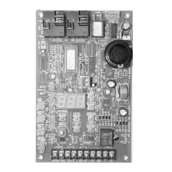
Beacon II Board Layout BEACON II BOARD Heater Relay Relay Display Room Sensor Defrost Sensor Suction Sensor Suction Pressure © 2004, Heatcraft Refrigeration Products LLC Expansion Valve Connection Selection Buttons Terminal Block... -
Page 4: Installation Tips
Installation Tips • Use a minimum 18 gauge wire for all low voltage connections. • The Beacon II board gets its 24 VAC power supply from a transformer mounted in the electrical end of each evaporator. On 208-240 volt systems the multi-tap transformer is shipped from our factory wired for 240 volts. -
Page 5: Brazing
Refrigerant Line Brazing ( CAUTION ) The electric expansion valve and the suction temperature sensor on the suction line are factory installed. Care must be taken when brazing these lines at the evaporator. Too high a temperature may destroy these components. Heat absorbing compounds or “wet rags”... -
Page 6: Multiple Evaporator Configuration
Wiring/Configuration WIRING (cont’d.) multi-in • Multiple units – The Connection sequence must follow the multi-out multi-in back to the • Alarm circuit - The onboard alarm is a dry set of NC contacts which closes to indicate an alarm. The type and wiring for the alarm is customer specified. Note that the alarm circuit does not distinguish or indicate what has caused the alarm. -
Page 7: Box Temperature Control Setting
Box Temp Control Settings BOX TEMPERATURE CONTROL SETTINGS • There is an on board room thermostat on the Beacon II board which can be adjusted to the desired room temperature. The temperature differential is 2 F. Temperature Differential When a system is in the cooling mode and the box setpoint is 35 F, the system will continue to cool until the box temperature gets to 34 F. -
Page 8: Start Up Operation
Start-Up Operation SINGLE SYSTEM with 1 EVAPORATOR • Check all wiring connections to be sure they are correct and tight. • On condensing unit - Check the setting of Time Delay relay. It should be set at 1 minute (the second marker). - Page 9 Start-Up Operation SINGLE SYSTEM with MULTIPLE EVAPORATORS • Check all wiring connections to be sure they are correct and tight. • On Condensing unit Check the setting of Time Delay relay. It should be set at 1 minute (the second marker). Check the Low Pressure switch setting on freezer units.
- Page 10 MULTIPLE SYSTEMS with MULTIPLE EVAPORATORS (Requires a Smart Controller) • Check all wiring connections to be sure they are correct and tight. • On condensing units - Check setting of Time Delay relay. It should be set at 1 minute (the second marker). - Check the Low Pressure Switch setting on freezer units.
-
Page 11: Operating Mode Display
INITIAL POWER ON At the initial application of power to the system, the compressor and the evaporator fans will be in a 4 minute hold-off cycle and will not start immediately. When there is a call for COOLING, the expansion valve (EEV) opens, then the compressor is started. The compressor will then run for a minimum of 2 minutes in the “hold-on”... -
Page 12: Programming And Reviewing Settings And Changes
Programming & Reviewing PROGRAMMING AND REVIEWING SETTINGS/CHANGES The Program Review button is used to program, review and change all program settings for the system. Press “PROGRAM REVIEW” button. The Setpoint item will appear on the LED. After a few seconds delay the Setpoint value will display. Each time the button is pressed a different setpoint item is displayed. - Page 13 Programming & Reviewing PROGRAMMING AND REVIEWING SETTINGS/CHANGES (cont’d.) Use the “PROGRAM REVIEW” button to select these items: Defrost Type – “A-E ” - Selection is made for air defrost or electric defrost coil. This will • automatically set the system factory defaults for air defrost and electric defrost. (See default settings.) Please note that the refrigerant type for electric defrost it is R404A.
-
Page 14: Monitoring Items
Programming & Reviewing PROGRAMMING AND REVIEWING SETTINGS/CHANGES (cont’d.) • Alarm High Temperature - “ ALH” - Temperature at which a high box temperature alarm will be triggered. This does not apply during defrost. and air defrost +50 F. • Alarm Low Temperature - “ALL” - Temperature at which a Low Box Temperature alarm Defaults: Electric Defrost -15 F and Air Defrost +30 F. -
Page 15: Locking Beacon Ii Board
Programming & Reviewing PROGRAMMING AND REVIEWING SETTINGS/CHANGES (cont’d.) Use this button to “CLEAR/TEST” Pressing this button ONCE will return the LED display to the default display. With the system in the OFF mode, pressing and holding this button will start the “TEST” mode. In the “TEST” mode it will cycle through each output for 10 seconds. -
Page 16: Status Indicator Led
Status Indicator LED STATUS INDICATOR LED • ERRORS • OTHERS Coo - Room Temperature sensor open or not connected Loc - Board is locked. Settings cannot be changed UnL - Unlock the board settings LOW AMBIENT OPERATION All units are shipped standard with Head Master valves. (Scroll compressor units have a 100 Psi Head Master valve and all other systems have a 180 Psi head master valve.) Condensing units with multiple condenser fans will have one or more fans cycle on Pressure Fan Cycling switch. -
Page 17: Defrost
Pumpdown / Defrost Service Mode A single pole, single throw switch (SPST) is supplied in each condensing unit for shutting off the system. Closing the “Service” switch in the condensing unit will cause the system to pumpdown and shut off. “Ser” will be displayed on the Beacon board LED and “SERVIC” is displayed on the Smart Controller LCD display. -
Page 18: Defrost
ELECTRIC DEFROST MODE When a defrost is initiated, the EEV closes, the compressor is allowed to pumpdown and shut off. The evaporator fans are cycled off and the defrost heaters are energized. On multiple evaporator systems, all controllers must terminate their defrost, either on temperature or fail-safe time, before the master controller will end the defrost cycle. -
Page 19: Error Indicator
ERROR INDICATOR LED At initial power up, each Beacon board checks for system errors. The system error check involves checking the various temperature sensors to determine whether any of these sensors are shorted or open. The system will pumpdown and cycle off and will not restart until the fault is cleared or the circuit breaker reset, for the following conditions: - Suction sensor shorted, open or not installed - Room temperature sensor shorted or not installed... -
Page 20: Checking Operation Of Expansion Valve
Checking Operation of Expansion Valve CHECKING OPERATION OF EXPANSION VALVE (EEV) To check if the expansion valve is closing properly: Install a pressure gauge-set to suction line at the condensing unit. With the system running, close the valve on the liquid line, at the condensing unit. The system should pumpdown and shut off on the Low Pressure switch (LPS). -
Page 21: Power Failures
Power Failures Measuring resistance between locations A and C or B and D will always show “Open” because these locations are between the motor windings. When the valve is opening or closing, the voltage measured between A and B or C and D should be between 20 to 22 VAC. -
Page 22: System Defaults
Table 1. Resistance/Temperature Specification Temperature F Ohms 5,320 8,060 10,000 12,490 15,710 19,900 25,400 Table 2. System Defaults PARAMETERS Refrigerant Box Temperature Superheat Slave Evaporator No. of Defrost per Day Defrost Fail-safe time Defrost End Temperature Defrost Delay Start Time Alarm High Temperature Alarm Low Temperature Alarm Time... -
Page 23: Parts List
Table 3. Parts List PART DESCRIPTION Beacon II Control Board *Temperature Sensor kit – White Leads Transformers: 120/24 volt– 40 VA 240/24 volt - 40 VA 460/24 volt – 40 VA 575/24 volt – 40 VA Pilot Relay Contactor for Compressor 40 amp with 24 volt Coil Terminal Block –... -
Page 24: Expansion Valve Capacity
Expansion Valve Capacity Pressure Drop Across Valve (psi) Part Number Valve 29320003 ESVB-1 0.68 29320004 ESVB-4 3.27 29320007 - 08 ESVB-10 8.02 29320013 ESVB-15 15.14 29320014 ESVB-20 22.18 Beacon II Troubleshooting Guide PROBLEM Step ACTION ITEM Check Primary Power Supply Disconnect Check Voltage to Evaporator Transformer LED is not lit. - Page 25 Beacon II Troubleshooting Guide (continued) PROBLEM Step ACTION ITEM Check wiring connection to the board Low Pressure Safety (LPS) Tripped: • Check for correct refrigerant type • Check refrigerant charge • Check LPS setting • Check LPS wiring • Check EEV operation (stuck?) •...
- Page 26 Beacon II Troubleshooting Guide (continued) PROBLEM Step ACTION ITEM Multi-out to Multi-in Check for 24 volts power to the board Communication Wiring (only shows after initial Check for crossed communication wiring successful connection) (multi-out not wired to multi-in terminals) Check for broken communication wiring (E9 continued) Master Communication Error...
-
Page 27: Diagnostics
Beacon II Troubleshooting Guide (continued) PROBLEM Step ACTION ITEM Check system operation: Is it running? Check system charge Check for proper operating superheat Check for high superheat and EEV wide open Check Low Pressure Safety Switch Cannot get to box Compare equipment capacity with requirements temperature Check box temperature setpoint... -
Page 28: Wiring Diagrams
Wiring... - Page 29 Wiring...
- Page 30 Wiring...
- Page 31 Wiring...
- Page 32 Wiring...
- Page 33 Wiring...
-
Page 34: Preventive Maintenance
Preventive Maintenance EVAPORATORS All evaporator units should be checked once a month or more often for proper defrosting because the amount and pattern of frosting can vary greatly. It is dependent on the coil temperature, the temperature of the room, the type of product being stored, how often new product is brought into the room and the percentage of time the door to the room is open. -
Page 35: Service Record
Date of Start-up Location Address CONDENSING UNIT MODEL # SERIAL # COOLER UNIT MODEL # SERIAL # FREEZER UNIT MODEL # SERIAL # ELECTRICAL • Check Primary Supply voltage. If 208 V, change transformer wiring in the Cooler and Freezer to the 208 V tap •... -
Page 36: Service Record
RECORD OUTDOOR TEMPERATURE SYSTEM VOLTAGE Cooler Compressor Amps Freezer Compressor Amps Cooler Discharge Pressure Freezer Discharge Pressure Cooler Suction Pressure Freezer Suction Pressure Cooler Suction Temp. Freezer Suction Temp. Cooler Refrigerant Charge Freezer Refrigerant Charge Cooler Compressor Superheat Freezer Compressor Superheat Cooler Evaporator Superheat Freezer Evaporator Superheat Cooler Discharge Temp.