Table of Contents
Advertisement
Quick Links
H-IM-80D
Replaces H-IM-80C (12/03)
Beacon II Smart Controller
Installation & Operation
Manual
February, 2004
Table of Contents
Features ................................................................2-3
Installation .............................................................4
Wiring ....................................................................5
Power Supply ........................................................6
Initialization of Beacon II Smart Controller ............7
Button Functions ...................................................7
Programming Beacon II Smart Controller ............. 8
Monitoring Beacon II Smart Controller ................. 9
Locking Beacon II Smart Controller ...................... 10
Error Codes ...........................................................10
Wiring Errors .........................................................11
Alarm Codes .........................................................11
Alarm Buzzer .........................................................12
Data Logging .........................................................12
Smart Defrost ........................................................13
PC & Modem Access ............................................14
System Defaults ....................................................15
Parts List ...............................................................16
Operational Limits .................................................16
Diagnostics ............................................................17-20
Wiring Diagrams ....................................................21-23
Part No. 25000601
Advertisement
Table of Contents

Related Manuals for Heatcraft Refrigeration Products 25000601


Summary of Contents for Heatcraft Refrigeration Products 25000601
-
Page 1: Table Of Contents
Error Codes ...10 Wiring Errors ...11 Alarm Codes ...11 Alarm Buzzer ...12 Data Logging ...12 Smart Defrost ...13 PC & Modem Access ...14 System Defaults ...15 Parts List ...16 Operational Limits ...16 Diagnostics ...17-20 Wiring Diagrams ...21-23 Part No. 25000601... -
Page 2: Features
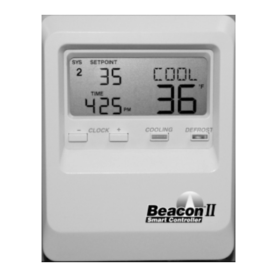
Temperature, the Current Time of day and the Mode (i.e. COOL, DEFROST or OFF). When multiple systems are being controlled, the system number (i.e. SYS 1, SYS 2, SYS 3, SYS 4) will also be displayed on the LCD. © 2004, Heatcraft Refrigeration Products LLC... - Page 3 Beacon II Smart Controller Features Features of the Beacon II Smart Controller • Monitoring of the complete refrigeration system. • Programming of a variety of parameters for the optimum control of the refrigeration system. • The Beacon II Smart Controller has a Liquid Crystal Display (LCD) which shows: current time, actual box temperature, box temperature set-point and if there is an alarm or fault condition.
-
Page 4: Installation
Installation INSTALLATION The Beacon II Smart Controller should be installed in a location where the large Liquid Crystal Display (LCD) can be viewed easily, yet is secure and vibration free. Because of the LCD screen, the Beacon II Smart Controller should not be mounted where it will experience temperatures below 40 F or above 100 F. -
Page 5: Wiring
WIRING All 24 volt wiring must be run separate from the line voltage wiring. All Low voltage wiring must be 18 gauge minimum and must be run separate from high voltage wiring. The maximum distance from the Beacon II Smart Controller to the Master Evaporator is 1000 ft. -
Page 6: Power Supply
The Beacon II Smart Controller can be supplied with it’s own power supply by using a 24 VAC Universal Plug-in Power Source with a minimum of 300 mA. When powered by an... -
Page 7: Initialization Of Beacon Ii Smart Controller
18 VAC. When this occurs the system will power down and shut off. When the power supply is corrected to 24 VAC, the system will restart after the four-minute hold off period and resume normal operation. The Beacon II Smart Controller LCD display will then be normal. -
Page 8: Programming Beacon Ii Smart Controller
Programming Beacon II Smart Controller • COOLING: Depressing this button will start the system in the cooling cycle immediately (The 4 minutes “Hold Off” is bypassed). This button will illuminate to indicate that the Cooling function is “ON”. System operation will be as described under REFRIGERATION MODE in the Beacon II installation manual. -
Page 9: Monitoring Beacon Ii Smart Controller
Monitoring With Beacon II Smart Controller SUPRHT • – Superheat: 4 to 20 F. Use “SETPOINT” slide-bar to select desired superheat temp., then press “ENTER.” If multiple evaporators are connected, use the “+” button to set other evaporators on this system. SMT DFT •... -
Page 10: Locking Beacon Ii Smart Controller
Locking Beacon II Smart Controller & Error Codes EXVSET • - Expansion valve step setting (Stepper Motor setting 0 to 255 steps: use + button to check other evaporators if Master/slave) SUCTMP • – Evaporator Suction temperature (Measured by the Suction Sensor) SSVTMP •... -
Page 11: Wiring Errors
Wiring Error & Alarm Codes *SPSEN - • Suction pressure transducer shorted, open or not installed *ODSEN - • Outdoor temperature sensor shorted *SUPLO - • Superheat too low *SHTDN - • Compressor shutdown (High or low refrigerant pressure or low oil pressure) The error code will flash alternately with the normal display information. -
Page 12: Alarm Buzzer
Alarm Buzzer & Data Logging The system will pumpdown, cycle off and try to restart for three consecutive times. Each try will be after the 4 minutes “Hold Off” period, for the following fault conditions. Oil pressure High pressure or low pressure cutout (or any other compressor safeties) After the fourth try, the Alarm contacts will be closed and an alarm message displayed on the LCD screen. -
Page 13: Smart Defrost
Real-time data can also be recorded and stored on a Desktop PC while the PC is connected to the Beacon II Smart Controller. The PC will continuously request information from the Beacon II Smart Controller regarding system operation and setup and record this data every minute, in an Excel spreadsheet. -
Page 14: Pc & Modem Access
PC And Modem Access PC & MODEM ACCESS For access to the system from a PC directly or via a modem, the SMART II Software must be purchased and installed on your PC. With PC access, ALL system settings can be monitored, changed or logged from a remote location. -
Page 15: System Defaults
SYSTEM DEFAULTS Following are factory defaults for the parameters which can be programmed in the Beacon II Smart Controller. If the user does not select a setting for any of the following parameters, the default will be used. It is important the user set ALL parameters based of their needs. PARAMETERS Refrigerant Box Temperature... -
Page 16: Parts List
Parts List PART DESCRIPTION Beacon II Control Board Temperature Sensor kit – White Leads* Transformer 120/24 volt – 40 VA Transformer 240/24 volt - 40 VA Transformer 460/24 volt – 40 VA Transformer 575/24 volt – 40 VA Pilot Relay Contactor for Compressor 40 amp with 24 volt Coil Terminal Block –... -
Page 17: Diagnostics
Beacon II Troubleshooting Guide PROBLEM Step ACTION ITEM Check Primary Power Supply Disconnect Check Voltage to Evaporator Transformer LED is not lit. Check Transformer Secondary Output Volts Check Voltage at Control Board (24V and C) Replace Control Board Check Compressor internal overloads... - Page 18 • Reduce superheat (TXV adjust, etc.) • Correct overheating problem • Consider crankcase pressure regulator or • Correct power phase problem • Correct power supply problems • Replace faulty PLM • Replace auxiliary relay • Replace faulty demand cooling device •...
- Page 19 Beacon II Troubleshooting Guide (continued) PROBLEM Step ACTION ITEM Multi-out to Multi-in Check for 24 volts power to the board Communication Wiring (only shows after initial Check for crossed communication wiring successful connection) (multi-out not wired to multi-in terminals) Check for broken communication wiring (E9 continued) Master Communication Error...
-
Page 20: Diagnostics
Beacon II Troubleshooting Guide (continued) PROBLEM Step ACTION ITEM Check system operation: Is it running? Check system charge Check for proper operating superheat Check for high superheat and EEV wide open Check Low Pressure Safety Switch Cannot get to box Compare equipment capacity with requirements temperature Check box temperature setpoint... -
Page 21: Wiring Diagrams
Wiring Diagrams... - Page 22 Wiring Diagrams...
-
Page 23: Wiring Diagrams
Wiring Diagrams... - Page 24 Wiring Diagrams...
- Page 25 Notes...
- Page 26 Notes...
- Page 27 Notes...
- Page 28 Since product improvement is a continuing effort, we reserve the right to make changes in specifications without notice. Heatcraft Refrigeration Products LLC 2175 West Park Place Blvd • Stone Mountain, GA 30087 (770) 465-5600 • Fax (770)465-5990 www.heatcraftrpd.com...