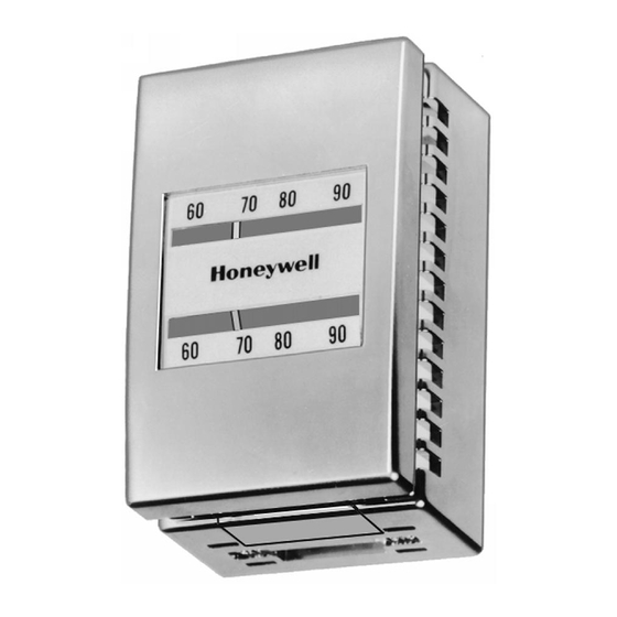
Honeywell TP970 Series Manual
Pneumatic thermostats
Hide thumbs
Also See for TP970 Series:
- Replacement data (13 pages) ,
- Engineering manual (228 pages) ,
- Service data (24 pages)
Table of Contents
Advertisement
Introduction
Fundamentals of
Thermostat Operation
TP973A, B and TP9630 A, B
Low-Capacity, Single-Temperature
Thermostats
TP970A-D and TP9600A, B
High-Capacity, Single-Temperature
Thermostats
TP971A-C and TP9610A, B
High-Capacity, Dual-Temperature
Thermostats
TP972A and TP9620A High-Capacity,
Heating/Cooling Thermostat
TP974A Room
Temperature Sensor
Copyright © 1997 Honeywell Inc. • All Rights Reserved
TP970 and TP9600 Series
Pneumatic Thermostats
.............................................................................................................................. 2
.............................................................................................................................. 2
General ................................................................................................................. 2
Flapper-Nozzle Operation .................................................................................... 2
Valve Unit Operation ............................................................................................ 2
.............................................................................................................................. 4
General ................................................................................................................. 4
Operation.............................................................................................................. 5
Direct Action .................................................................................................. 5
Reverse Action .............................................................................................. 5
.............................................................................................................................. 6
General ................................................................................................................. 6
Operation.............................................................................................................. 6
Direct Action .................................................................................................. 6
Reverse Action .............................................................................................. 7
.............................................................................................................................. 7
TP971B and TP9610B ......................................................................................... 7
TP971C ................................................................................................................ 7
TP971A and TP9610A ......................................................................................... 7
Daytime Operation ............................................................................................... 8
Nighttime Operation ............................................................................................. 8
Manual DAY Override........................................................................................... 9
.............................................................................................................................. 10
General ................................................................................................................. 10
Operation.............................................................................................................. 12
.............................................................................................................................. 12
General ................................................................................................................. 12
Operation.............................................................................................................. 12
ENGINEERING DATA
Contents
77-9382-1
Advertisement
Table of Contents

Summary of Contents for Honeywell TP970 Series
-
Page 1: Table Of Contents
Nighttime Operation ..................... 8 Manual DAY Override................... 9 TP972A and TP9620A High-Capacity, Heating/Cooling Thermostat ..........................10 General ......................... 10 Operation......................12 TP974A Room Temperature Sensor ..........................12 General ......................... 12 Operation......................12 77-9382-1 Copyright © 1997 Honeywell Inc. • All Rights Reserved... -
Page 2: General
TP970 AND TP9600 SERIES PNEUMATIC THERMOSTATS INTRODUCTION throttling range (TR) adjustment) has a fixed branchline pressure (BLP) for each temperature within the temperature and throttling range settings. The forces within the nozzle- This Engineering Data sheet provides detailed information flapper-bimetal assembly always seek a balanced condition; on the operation of TP970 and TP9600 Series Pneumatic giving the same BLP for the same temperature regardless of Thermostats (Thermostats). - Page 3 TP790 AND TP9600 SERIES PNEUMATIC THERMOSTATS THROTTLING RANGE CALIBRATION ADJUSTMENT SCREW BIMETAL NOZZLE FLAPPER BRANCHLINE PRESSURE TAP SETPOINT BRANCHLINE CHAMBER SETPOINT KNOB FILTER BLEED RESTRICTOR PILOT EXHAUST PILOT VALVE MAIN BRANCH LINE CHAMBER C6047-1 LINE Fig. 2. Cross Section of TP970 and TP9600 Thermostat Showing Valve Unit and Airflow. TP970, TP9600, TP971, TP9610, TP972, and TP9620 Figure 4 shows the valve unit supplying air to the branch Thermostats are designed around a valve unit for flow...
-
Page 4: General
TP970 AND TP9600 SERIES PNEUMATIC THERMOSTATS Figure 5 shows the valve unit bleeding down the BLP. This condition occurs when the bimetal sensing element relaxes its force against the flapper, allowing the nozzle-flapper gap to increase. POINT A VALVE POINT B PISTON MAIN LINE BRANCH... -
Page 5: Operation
TP790 AND TP9600 SERIES PNEUMATIC THERMOSTATS forces in the lever system go out of balance and the room SETPOINT KNOB ambient temperature changes to rebalance the lower THROTTLING RANGE CALIBRATION system. ADJUSTMENT SCREW BIMETAL For example, if the setpoint cam is moved to a higher FLAPPER temperature setting, the point of the lever system that rides the slope of the cam lowers (direct-acting device) due to this... -
Page 6: General
TP970 AND TP9600 SERIES PNEUMATIC THERMOSTATS The Thermostat provides a BLP that is a function of ambient BRANCH LINE PRESSURE GAGE PORT temperature. The force from the bimetal acting on the flapper is balanced by the feedback force of the BLP acting on the opposite side of the flapper through the nozzle. -
Page 7: Reverse Action
TP790 AND TP9600 SERIES PNEUMATIC THERMOSTATS TP971A and TP9610A SETPOINT KNOB THROTTLING RANGE CALIBRATION ADJUSTMENT SCREW On the TP971A and TP9610A direct-acting Thermostats (Fig. BIMETAL 12), the daytime bimetal controls the system when the main FLAPPER air pressure is 13 psi (90 kPa). The nighttime element controls the system when the main air pressure reaches 18 psi (124 kPa). -
Page 8: Daytime Operation
TP970 AND TP9600 SERIES PNEUMATIC THERMOSTATS Daytime Operation Nighttime Operation Figure 13 shows airflow through the Thermostat during In Figure 14, the main air pressure is at 18 psi (124 kPa) for daytime operation. The main air pressure is at the lower, nighttime operation. -
Page 9: Manual Day Override
TP790 AND TP9600 SERIES PNEUMATIC THERMOSTATS SECONDARY BRANCH DAY/AUTO LEVER MANUAL DAY LOGIC MODULE A LOGIC LOGIC MODULE C MODULE D SPRING BLEED 2 18 PSI (124 kPa) NIGHT DIAPHRAGM BLEED 1 SPRING LOGIC PORT B2 MODULE B 13 PSI (90 kPa) MAIN LINE PILOT PORT B1... -
Page 10: General
TP970 AND TP9600 SERIES PNEUMATIC THERMOSTATS NOZZLE SECONDARY BRANCH DAY/AUTO LEVER MANUAL DAY LOGIC MODULE A LOGIC LOGIC MODULE C MODULE D SPRING BLEED 2 18 PSI (124 kPa) NIGHT DIAPHRAGM BLEED 1 SPRING LOGIC PORT B2 MODULE B 13 PSI (90 kPa) MAIN LINE PILOT CHAMBER... - Page 11 TP790 AND TP9600 SERIES PNEUMATIC THERMOSTATS The TP972A and TP9620A have one setpoint adjustment TP9610 except for the logic modules, the manual override, knob that controls both heating and cooling bimetals. Each and the independent setpoint adjustment. Cooling control bimetal has an independent throttling range adjustment requires a lower pressure in the main air supply.
-
Page 12: Operation
GAGE OR CONTROL) LINE C6064 Fig. 19. Cross Section of TP974A—Two-Pipe Application. Home and Building Control Home and Building Control Honeywell Inc. Honeywell Limited-Honeywell Limitée Honeywell Plaza 155 Gordon Baker Road P.O. Box 524 North York, Ontario Minneapolis MN 55408-0524 M2H 3N7 Printed in U.S.A.


