Honeywell TROL-A-TEMP Q674B Installation Instructions Manual
Zone thermostats/subbases
Hide thumbs
Also See for TROL-A-TEMP Q674B:
- Installation instructions manual (8 pages) ,
- Installation instructions manual (8 pages)
Table of Contents
Advertisement
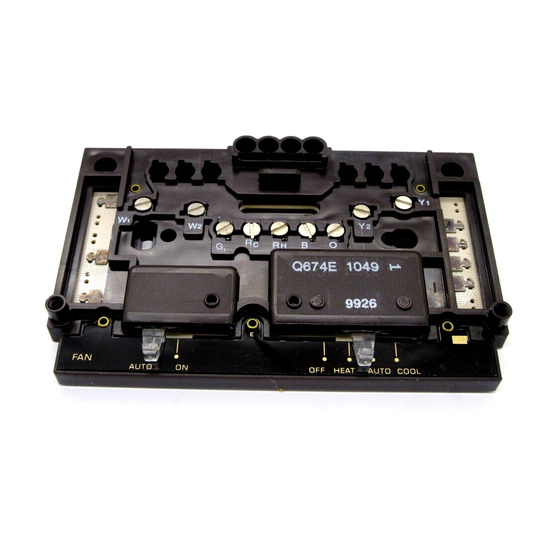
These T874A,D Zone Thermostats and Q674B,D,E
Subbases provide 24 to 30 Vac temperature control in
Honeywell Trol-A-Temp heating/cooling zone systems.
TABLE 1—THERMOSTAT/SUBBASE AND SYSTEM COMPATIBILITY.
Subbase Model
a
Number
T874A/Q674B Zone 1; conventional
heat-cool.
T874A/Q674D Zones other than zone 1;
conventional heat-cool.
T874A/Q674E Not applicable
T874D/Q674B Not applicable
T874D/Q674D Not applicable
T874D/Q674E Not applicable
a
Subbase not included with thermostat; order separately.
Thermostat/Subbase
a
Order Number
T874A1465/Q674B1471 HEAT-OFF-COOL
T874A1465/Q674D1123 None
T874A1465/Q674E1379 HEAT-OFF-COOL-AUTO ON-AUTO
T874D1801/Q674B1463 HEAT-OFF-COOL
T874D1827/Q674B1471 HEAT-OFF-COOL
T874D1801/Q674D1115 None
T874D1827/Q674D1123 None
T874D1827/Q674E1379 HEAT-OFF-COOL-AUTO ON-AUTO
a
Subbase not included with thermostat; order separately.
On a 2-heat thermostat, the two stages of heat make
sequentially as the temperature drops. Make refers to the
mercury switch initiating a call for heat or cool.
There are about 2° F [1° C] between stages so that the
second stage makes only when the first stage cannot
handle the load. This is the interstage differential.
T874A,D Zone Thermostats/
Installation Instructions for the Trained Service Technician.
Application
Mini-Zone
Mabs II, Mabs II-L
Zone 1; conventional
heat-cool.
Zones other than zone 1;
conventional heat-cool.
Not applicable
Zone 1; conventional
heat-cool.
Zones other than zone 1;
conventional heat-cool
and heat pump.
Not applicable
TABLE 2—THERMOSTAT/SUBBASE SPECIFICATIONS.
Switching
System
Operation
S. M. • Rev. 6-93 •
Q674B,D,E Subbases
See Table 1 for thermostat/subbase and system compatibil-
ity; see Table 2 for thermostat specifications. For complete
Honeywell Trol-A-Temp System specification and appli-
cation information, refer to the system specification in-
cluded with the control panel.
Application
Any zone; conventional heat-cool. Single-stage
Not applicable
Any zone; conventional heat-cool. Single-stage
Any zone; conventional heat-cool. Multistage
Not applicable
Any zone; conventional heat-cool. Multistage
Thermostat/
Subbase
Fan
Color
ON-AUTO
White/Gray
None
White/Gray
White/Gray
ON-AUTO
Beige/Brown
ON-AUTO
White/Gray
None
Beige/Brown
None
White/Gray
White/Gray
This control contains mercury in a sealed tube. Do not
place control in the trash at the end of its useful life.
If this control is replacing a control that contains mercury
in a sealed tube, do not place your old control in the trash.
Contact your local waste management authority for
instructions regarding recycling and the proper disposal of
this control, or of an old control containing mercury in a
sealed tube.
If you have questions, call Honeywell at 1-800-468-1502.
• ©Honeywell Inc. 1993 • Form Number 69-0580—2
M3375
Mabs XX
Anticipator Range (A)
(Adj.)
Stg. 1—
0.1 to 1.2
Stg. 1—
0.1 to 1.2;
Stg. 2—
0.1 to 1.0.
Recycling Notice
M3375
Stages
Single-stage
Multistage
(Fixed)
Stg. 1—
0 to 1.5
Stg. 1—
0 to 1.2;
Stg. 2—
0 to 1.0.
Advertisement
Table of Contents

Related Manuals for Honeywell TROL-A-TEMP Q674B


Summary of Contents for Honeywell TROL-A-TEMP Q674B
- Page 1 If you have questions, call Honeywell at 1-800-468-1502. S. M. • Rev. 6-93 • • ©Honeywell Inc. 1993 • Form Number 69-0580—2...
- Page 2 Installation Fig. 1—Installation of subbase on outlet box. WHEN INSTALLING THIS PRODUCT… 1. Read these instructions carefully. Failure to fol- low them could damage the product or cause a hazard- ous condition. 2. Check the ratings given in the instructions and on the product to make sure the product is suitable for your HORIZONTAL OUTLET...
- Page 3 letter code is located near each subbase terminal for identi- fication. The terminal barrier permits straight or conven- Fig. 5—Jumper RC and RH terminals for single transformer system. Strip wire 3/4 in. [19 mm]. tional wraparound wiring connection (Fig. 4). 2.
-
Page 4: Mounting The Thermostat
MOUNTING THE THERMOSTAT spring fingers are not bent flat, preventing proper electri- 1. Remove the thermostat cover by pulling the bottom cal contact with the subbase. edge of the cover outward away from the base until it snaps 4. Set the heat anticipator indicator(s) to 0.1A for free from the cover clip. - Page 5 Fig. 8—Typical hookup for MABS II and MABS II-L Control Panels with T874D Thermostat/Q674B,D Subbases in multistage heating-cooling zone system. MABS II Control Panel shown; MABS II-L Control Panel hookup is the same. T874D THERMOSTAT/ T874D THERMOSTAT/ Q674D SUBBASE Q674D SUBBASE T874D THERMOSTAT/Q674B SUBBASE RC Y2 RC Y2...
- Page 6 Fig. 9—Typical hookup for MABS XX Control Panel with T874A Thermostat/Q674B,E Subbases in single- stage heating-cooling zone system. MABS XX CONTROL PANEL ZONE 1 ZONE 2 ZONE 3 HEAT COOL HEAT COOL HEAT COOL ZONE 1 ZONE 2 ZONE 3 ZONE ZONE ZONE...
- Page 8 Settings...
- Page 9 Checkout Before beginning checkout of thermostat operation, To set up the system for thermostat checkout, adjust set switches on the control panel for the desired system each thermostat settings as shown in Table 5. operation. See instructions provided with the control panel. TABLE 5—SYSTEM SET-UP FOR THERMOSTAT CHECKOUT.
- Page 10 After making each adjustment, wait ten minutes for the thermometer to stabilize before comparing. Home and Building Control Home and Building Control Helping You Control Your World Honeywell Inc. Honeywell Limited—Honeywell Limitée 1985 Douglas Drive North 740 Ellesmere Road Golden Valley, Minnesota 55422 Scarborough, Ontario M1P 2V9 QUALITY IS KEY Printed in U.S.A.