Table of Contents
Advertisement
Advertisement
Table of Contents

Related Manuals for Huffy Cruiser Bicycles


Summary of Contents for Huffy Cruiser Bicycles
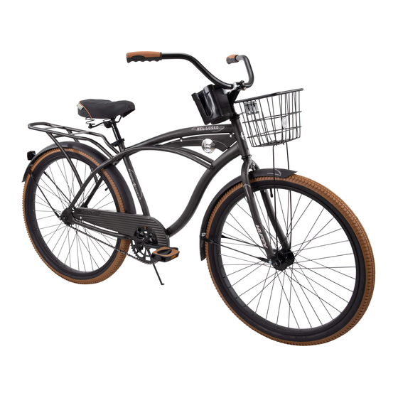
- Page 1 Owner’s Manual for Cruiser Bicycles This manual contains important safety, assem- bly, operation and maintenance information. Please read and fully understand this manual before operation. Save this manual for future reference. m0058 HCA EN 112612 Copyright Huffy Corporation 2012...
-
Page 2: Table Of Contents
Maintenance and Service • Tires ..................... 22 • Repair and Service ................23 • Lubrication .................... 23 • Lubrication Table................... 24 • Inspection of the Bearings ..............24 • Refl ectors ..................... 24 Huffy Warranty • Huffy Corporation Limited Warranty ............. 26... -
Page 3: Owner's Bicycle Identifi Cation Record
Owner’s Bicycle Identifi cation Record NOTE: This information is only available on the bicycle itself. It is not available from Huffy. Each Huffy bicycle has a Serial Number stamped into the frame. The Serial Number (1) can be found on the bottom of the crank housing as shown. -
Page 4: Warning And Safety Information
Warning and Safety Information Meanings of Warnings: This symbol is important. See the word “CAUTION” or “WARNING” which follows it. The word “CAUTION” is before mechanical instructions. If you do not obey these instructions, mechanical damage or failure of a part of the bicycle can occur. -
Page 5: The Owner's Responsibility
• Do not let anything cover the refl ectors. • Use extra caution in wet weather: • Ride slowly on damp surfaces because the tires will slide more easily. • Avoid these hazards to prevent loss of control or damage to your wheels: •... -
Page 8: Introduction
Introduction This Owner’s Manual is made for several different bicycles: • Some illustrations may vary slightly from the actual product. • Follow instructions completely. • If the bicycle has any parts that are not described in this manual, look for separate “Special Instructions”... -
Page 9: Front Fender Installation
Front Fender Installation Use Screw Driver and Wrench: 1. Front fender attaching hardware has been pre-assembled onto the fork. Remove the Bolt (8) and Washer (9) and Nut (10) from the fork crown. 2. Remove lower mounting Bolts (7) and Washers (6) from the dropout before starting (fi... - Page 10 Front Fender Installation Continued: Model without Front Refl ector: 8. Place the Fender (3) in the fork with the longer fork mounting tab (A) on the rear side of the fork (fi g 02). 9. Insert the Bolt (8) through the Washer (9) and Fender Tabs (A,D) and fork mounting hole.
-
Page 11: Assemble The Front Wheel To The Fork (Without Basket)
Assemble the Front Wheel to the Fork (without basket) 1. If the Axle Nuts (5) are already attached to the front wheel axle, begin by removing them with an open end wrench or adjustable wrench. 2. Set the wheel into the front fork (21) (fi g 04). 3. -
Page 12: Mounted Wire Basket Assembly
Mounted Wire Basket Assembly (if equipped) 1. Attach Support Legs (39) to bot- tom of Basket (35) using Bracket (40), Screws (36) [x2], Wash- ers (37) [x2] and Nuts (38) [x2]. Tighten Securely. 2. Make sure Support Legs (39) set between Bracket (40) and Basket (35) (fi... -
Page 13: Rear Fender Assembly
Rear Fender Assembly Note: Top Fender mount is loose (fi g 06) to allow installation. 1. Line up the Rear Fender Braces (A) with the Frame Mounting Tabs (B) (fi g 05). 2. Insert each lower mounting Bolt (7) and Washer (6) into the Frame Mount- ing Tabs (B) and tighten securely. -
Page 14: Handlebar And Stem Installation
Handlebar and Stem Installation WARNING: To prevent steering system damage and possible loss of control, the “MIN-IN” (minimum insertion) mark (A) on the stem must be below the top of the Locknut (B). NOTE: Remove plastic Cap (E) from the end of the Stem (13). 1. -
Page 15: Testing Stem And Handlebar Tightness
Testing Stem and Handlebar Tightness To test the tightness of the stem: • Straddle the front wheel between your legs. • Try to turn the front wheel by turning the handlebar. • If the handlebar and stem turn without turning the front wheel, realign the stem with the wheel and tighten the stem bolt(s) tighter than before (about 1/2 revolution only at a time). -
Page 16: Seat Installation
Seat Installation Attach Seat to Seat Post (fi g 09): (pre-assembled on some models) • Loosen nuts on seat clamp (A) and rotate Seat (14) into riding position. • Put the seat post (33) fully through the seat clamp (A). •... -
Page 17: Testing Seat Clamp And Post Clamp Tightness
CAUTION: Operate the Quick Release Lever (D) by hand only. Do not use a hammer or any other tool to tighten the quick release lever. You must use strong force to move the quick release lever to the “close” posi- tion. -
Page 18: Pedal Installation
Pedal Installation CAUTION: There is a right pedal marked “R” and a left pedal marked “L”. • The pedal marked “R” has right-hand threads. Tighten it in a clockwise direction. • The pedal marked “L” has left-hand threads. Tighten it in a counterclock- wise direction (anti-clockwise). -
Page 19: Front Refl Ector Bracket Installation
Front Refl ector Bracket Installation 1. Position Refl ector (17) so it points straight forward (fi g 12). 2. Tighten Clamp Screw. NOTE: Do not over-tighten. This will damage the Clamp. fig 12 Luggage Rack Adjustment 1. Loosen Adjustment Knob (48) by turning counter clockwise. 2. -
Page 20: Handlebar Bags/Basket
Handlebar Bags and Baskets (various models) Bag or Basket Installation: 1. Attach Bag (44) or Basket (50) to Handlebar using the two Straps. 2. Tighten Straps so Bag/Basket does not move. NOTE: Do not over tighten. The Straps may break. Insulated Bag Installation (various models): 1. -
Page 21: Brake System
Brake System These models are equipped with a rear ‘coaster’ brake that is operated by rotating the crank backwards (fi g 15). fig 15 Chain Adjustment WARNING: The chain must remain on the sprock- ets. If the chain comes off the sprockets, the coaster brake will not operate. -
Page 22: Tires
Tires Maintenance: • Frequently check the tire infl ation pressure because all tires lose air slowly over time. For extended storage, keep the weight of the bicycle off the tires. • Do not use unregulated air hoses to infl ate the inner tubes. An unregulated hose can suddenly over infl... -
Page 23: Repair And Service
Repair and Service WARNING: • Inspect the bicycle frequently. Failure to inspect the bicycle and to make repairs or adjustments, as necessary, can result in injury to the rider or to others. Make sure all parts are correctly assembled and adjusted as written in this manual and any “Special Instructions”. -
Page 24: Lubrication Table
Lubrication Table What When Pedals every six months Put four drops of oil where the axles go into the pedals. Chain every six months Put one drop of oil on each roller of the chain. Wipe all excess oil off the chain. Inspection of the Bearings Maintenance Frequently check the bearings of the bicycle. - Page 25 NOTES...
-
Page 26: Huffy Corporation Limited Warranty
Used in a manner contrary to the instructions and warnings in this Owner’s Manual Huffy will not be liable for incidental or consequential loss or damage, due directly or indirectly from use of this product. Some states do not allow the exclusion or limitation of incidental or consequential damages, so the above limitation may not apply to you. - Page 27 All other components are warranted for six (6) months from the date of purchase. What will Huffy do? Huffy will replace, without charge to you, the component found to be defective by Huffy. The original owner must pay all labor and transportation charges connected with the repair or warranty work.
- Page 28 • Always read the user manual that comes with your helmet to make sure it is fi tted and attached properly to the wearer’s head according to the fi tting instructions described in the user manual. Check www.Huffy.com for the current contact information H Helmet EN 100212 i0027...