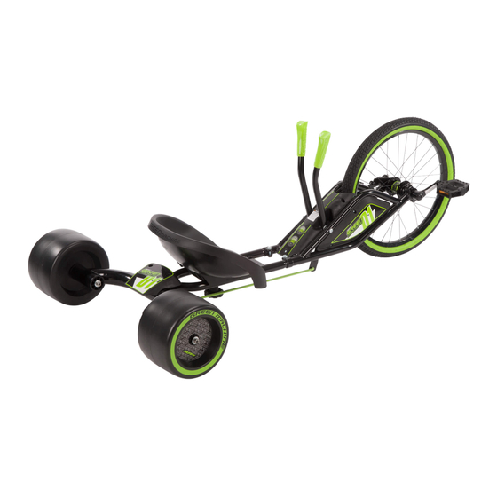
Huffy Green Machine Owner's Manual
Hide thumbs
Also See for Green Machine:
- Owner's manual (118 pages) ,
- Owner's manual (21 pages) ,
- Owner's manual (16 pages)
Table of Contents
Advertisement
Advertisement
Table of Contents

Related Manuals for Huffy Green Machine


Summary of Contents for Huffy Green Machine
- Page 1 Owner’s Manual This manual contains important safety, assembly, operation and maintenance information. Please read and fully understand this manual before operation. Save this manual for future reference. Date Code Label Here m0301 HGM-G-9 20 EN-AU 091515 Copyright Huffy Corporation 2015...
-
Page 2: Table Of Contents
Your Green Machine • Owner’s Model Identification Record ............. 3 • Warning and Safety Information ............4-5 • Assembly Notes - Tools Needed............6 • Operating Your Green Machine ............7-9 • Coaster Brake ..................9 Model Assembly • Parts Assembly List ................10-11 •... -
Page 3: Owner's Model Identification Record
Owner’s Model Identification Record NOTE: This information is only available with model itself. It is not available from Huffy. Model number is on the packaging and instruction manual. Write the model number below to keep it for future reference. If the model is stolen, give this number and a description of the model to the police. -
Page 4: Warning And Safety Information
Warning and Safety Information PLEASE READ AND FULLY UNDERSTAND THIS OWNERS MANUAL BEFORE OPERATING THE PRODUCT This symbol is important. See the word “CAUTION” or “WARNING” which fol- lows it. The word “CAUTION” is before mechanical instructions. If you do not obey these instructions, mechanical damage or failure of a part of the product can occur. -
Page 5: Warning And Safety Information
Warning and Safety Information - continued • Do not pull any objects with the product. • Do not push the product. • Never ride with more than one person. Maximum weight is 180 lbs (82Kg). • Excessive weight may cause a hazardous or unstable condition. •... -
Page 6: Assembly Notes - Tools Needed
Assembly Notes The instructions in this manual refer to the right and left side of the product, these are defined from the rider position. Do not discard any parts until the unit is com- pletely assembled. NOTE: Check Front Tire Pressure before first ride! Required Tools 13mm socket (supplied) Metric Allen Wrench (supplied) -
Page 7: Operating Your Green Machine
Steering your Green Machine Steering Function: • Pulling back on the left lever, and pushing forward on the right lever will turn the product towards the left. • Pulling back on the right lever, and pushing forward on the left lever will turn the product towards the right. - Page 8 Leaning into a Turn Lean INTO a LEFT Turn Lean INTO a RIGHT Turn WARNING: Failure to lean in the direction of the turn as shown can result in the unit rolling over.
-
Page 9: Coaster Brake
Coaster Brakes These models are equipped with a ‘coaster’ brake that is operated by rotating the crank backwards. Operation: Operate the coaster brake as follows: • Push the pedal down and forward as shown. • As you push the pedals with increasing force, the braking action of the coaster brake increases. - Page 10 Parts Assembly View...
-
Page 11: Parts Assembly List
Parts Assembly List... -
Page 12: Assemble Front Frame To Rear Frame
Assemble Front Frame to Rear Frame STEPS: NOTE: Mounting Screws (A) may be pre installed at the factory. 1. Begin by loosening Screws (A) slightly. 2. Make sure rear section of Frame (B) is right side UP: Rear Stop (C) will be on the top of the Frame. -
Page 13: Steering Arms
Steering Arms NOTE: The Steering Arms (A) are pre-assembled at the factory. Periodically check tightness of Bolts/Screws (B). See Torque Chart for recommended torques. -
Page 14: Assemble Steering Linkage
Attaching Steering Linkage - Front FORWARD STEP 1: 1. Insert end of Right Steering Rod (A) with SHORTER End (B) into Steering Rod Handle Ends (C) as shown on right side of unit. 2. Make sure Rods are on the OUTSIDE (view D) of the Steering Rods as shown and back of Rods are pointing UP (E). - Page 15 Attaching Steering Linkage - Rear STEP 2: 1. Rotate Rear Axle (A) UP 90°. 2. Move Frame (B) slightly to the side. 3. Insert both Steering Rods (C) into Pivot Bracket holes (D) as shown. Proceed to next step >>...
-
Page 16: Assemble Rear Steering Axle
Assemble Rear Steering Axle STEP 3: 1. Rotate Rear Axle back to horizontal, while moving Frame (A) into place between Pivot Bracket holes (B). 2. Swing the Frame (A) into the Pivot Bracket (B) so the mounting holes line up. 3. - Page 17 Installing Pivot Bolt Cover STEPS: NOTE: Screws (C) maybe pre-installed in Rear Axle Plate (B). Remove and set aside. 1. Place Pivot Bolt Cover (A) over Rear Axle Plate (B) so that mounting holes line 2. Install two Screws (C) through Cover and into Rear Axle Plate. 3.
-
Page 18: Assemble Rear Wheels
Installing Rear Wheels STEPS: NOTE: Axle may be Bolt style or Threaded Rod style (D). Threaded Rod style will have a Washer (F) and Lock Nut (G) on both ends. Bolt Style will have a larger Washer (C) under the head of the Bolt. 1. -
Page 19: Installing Seat
Installing Seat SEAT: 1. Place Seat (A) over Frame Seat Holes (B) (adjust Seat position for proper fit). 2. Insert Washer (C) and Seat Bolt (D) through Seat as shown. 3. Attach Adjustment Knob (E) to Seat Bolt (D) from underneath. 4. -
Page 20: Installing Pedals
Installing Pedals 1. Install the pedal marked “R” (Right) on the right side. Tighten clockwise as shown. 2. Install pedal marked “L” (Left) on the left side. Tighten counterclockwise as shown. 3. Make sure threads of each pedal are fully into crank arm. 4. -
Page 21: Repair And Service
Repair and Service WARNING: • Inspect the model frequently. Failure to inspect the model and to make repairs or adjustments, as necessary, can result in injury to the rider or to others. Make sure all parts are correctly assembled and adjusted as written in this manual and any “Special Instructions”. -
Page 22: Tires
Tires Maintenance: • Frequently check the tire inflation pressure because all tires lose air slowly over time. For extended storage, keep the weight of the model off the tires. • Do not use unregulated air hoses to inflate the inner tubes. An unregulated hose can suddenly over inflate model tires and cause them to burst. -
Page 23: Tire/Tube Replacement
Tire and Tube Replacement STEP 1 - Remove Existing Tire and Tube: Steps (start opposite Filler Valve): 1. Insert a Tire Lever under Tire Bead (A). 2. Hook end of Tire Lever on a spoke. 3. Insert second Tire Lever and slide along rim to remove tire bead. 4. -
Page 24: Lubrication And Lubrication Table
Lubrication WARNING: • Do not over lubricate. If oil gets on the wheel rims or the brake shoes, it will reduce brake performance and a longer distance to stop the model will be neces- sary. Injury to the rider or to others can occur. •... -
Page 25: Inspection Of The Bearings
Inspection of the Bearings Maintenance Frequently check the bearings of the model. Lubricate or have a bicycle service shop lubricate the bearings once a year or any time the front wheel does not spin freely and easily. Wheel Bearings Lift the front wheel off the ground and slowly spin the wheel by hand. The bearings are correctly adjusted if: •... - Page 26 • Used in a manner contrary to the instructions and warnings in this Owner’s Manual Huffy will not be liable for incidental or consequential loss or damage, due directly or indirectly from use of this product. Some states do not allow the exclusion or limitation...
- Page 27 What will Huffy do? Huffy will replace, without charge to you, the component found to be defective by Huffy. CONTACTING CUSTOMER SERVICE: How do you report a problem with this product or submit a warranty claim? •...
- Page 28 • Always read the user manual that comes with your helmet to make sure it is fi tted and attached properly to the wearer’s head according to the fi tting instructions described in the user manual. Check www.Huffy.com for the current contact information...