Summary of Contents for Honeywell DTC 100/2
-
Page 1: User Manual
DTC 100/2 Differential thermostat for solar system and combined multi-source heating DTC 100/2 User manual Instructions for installation and maintenance ID-2106-04-DTC100-2-Honey-170100.indd... -
Page 2: Dear Customer
Thanks for your trust, THE KIT INCLUDES: 1. Differential thermostat DTC 100/2 2. Sensor T1 with a silicon conductor for the collectors 3. Sensor T2 with a PVC conductor for the DHWS 4. A clamp with two fastening springs - to fasten the sensor 5. -
Page 3: General Information
DHWS. OPERATION Single differential thermostat DTC 100/2 measures the temperature in the source (collec- tors, the stove) and in the consumer (DHWS). In order to achieve heating effects, the temperature of the heating body (the heater in the boiler) needs to exceed the temperature of the water in the consumer (the boiler) by at least 3 to 5 K. -
Page 4: Installation Of The Thermostat
DTC 100/2 INSTALLATION OF THE THERMOSTAT The thermostat is fastened upon the coat of the DHWS (Domestic Hot Water Storage) or to its immediate neighbourhood. By simply using the outline of the boreholes drawn on page 11 of this booklet, the thermostat can easily be fastened to the wall in the heating room. Do not fasten the thermostat below tube joints or valves to avoid water dropping on its housing. -
Page 5: Electrical Connection
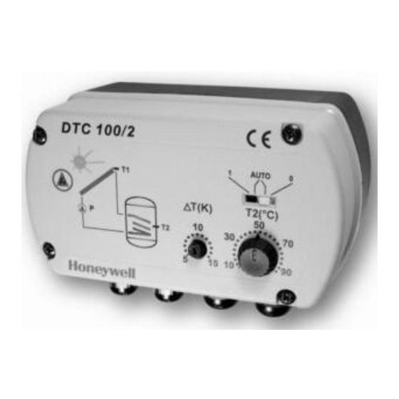
DTC 100/2 ELECTRICAL CONNECTION The grounding cables are to be connected to the specially designed terminals, to the right of the coupling terminals. TERMINAL CONNECTION sensor T1 - sensor of the source (collector) KF, silicon, 2x0.25 mm 2 m long, with two spring ribbons and one angle clamp, orange sensor T2 - DHWS sensor, 2x0.34mm2 1.5 m long, gray... - Page 6 DTC 100/2 DESCRIPTION OF THE FRONT PANEL ELEMENTS LEGEND : 1 - The switch for manual control (selection of a mode of operation) 2 - Button for adjustment of the temperature of the water in the DHWS (operates only when the gliding switch (1) is in position AUTO.) 3 - Potentiometer for the adjustment of the switching off temperature difference be tween the DHWS and the source of heating.
- Page 7 DTC 100/2 Setting the temperature in the DHWS By turning the right button (2) on the cover of the thermostat, you can set the maximum temperature of the water in the DHWS (Domestic Hot Water Storage) between 10 and 90°C. When the set temperature is achieved, the thermostat closes the valve and turns off the pump.
- Page 8 DTC 100/2 Basic coupling with a pump controlled by an electric motor actuated ball valve ( EMV 110 series 800) When the conditions required for the boiler to star heating are met, the EMV 110 series 800 opens. The pump however, is put into operation only when the valve is open.
- Page 9 DTC 100/2 Example of coupling with a pump. In this case it is necessary to connect behind the pump a non-return valve to avoid unwanted circulation of water. Differential thermostat DTC 100/2 T1, T2 Sensors T1 - sensor located in the collector...
- Page 10 DTC 100/2 Basic coupling with a pump controlled by the electri- cally actuated motor ball valve EMV 110 series 800. It is used in cases which require temperature regulation of sanitary water in the classical oil or solid fuel powered boiler. When the conditions which require heating of the DHWS (Domestic Hot Water Storage) have been met, the valve EMV 110 series 800 opens , but the pump is put into operation only when the valve is open.
- Page 11 DTC 100/2 An outline of borehole positions - to facilitate the installation of the differential thermostat upon the wall.
- Page 12 DTC 100/2 Most frequently occuring failures PROBLEM POSSIBLE FAILURE ELIMINATION No matter what the - there is no mains voltage - check the mains voltage temperature is, the - the switch is in 0-position - put the switch into AUTO...


