Table of Contents
Advertisement
Quick Links
Advertisement
Table of Contents

Related Manuals for Zanussi ZGF 646


Summary of Contents for Zanussi ZGF 646
- Page 1 GAS HOBS ZGF 646 OPERATING AND INSTALLATION MANUAL...
-
Page 2: For Your Safety
Repairs carried out by installing a cooker hood with discharge tube. unexperienced persons may cause injury or serious malfunctioning. Refer to your local Zanussi Service • In case of intensive or long time use of the Centre. Always insist on genuine Zanussi spare appliance, make the ventilation more efficient, parts. -
Page 3: Table Of Contents
Contents 1. Instruction for the User ..... Pag. 5. Technical Data ......Pag. 2. Cleaning and Maintenance ..Pag. 6. Instruction for the Installer ..Pag. 3. Periodic Maintenance ....Pag. 7. Electrical Connection ....Pag. 8. Adaptation to different 4. -
Page 4: Cleaning And Maintenance
THE HOB LID In order to make the appliance match with the kitchen Always clean the lid from cooking residues before design, a lid (not provided) can be fitted on the hob. opening it or taking it off. The lid is meant to avoid dust to settle on the hob, WARNING! The crystal lid can splinter when when it is closed, and to collect splashes of oil or overheated. -
Page 5: Periodic Maintenance
FO 2237 ENAMELLED PAN SUPPORTS In hobs provided with enamelled pan supports, these can be removed and kept in the right position thanks to special hinges in the back of the hob (see fig. 4 and 5). This solution enables rapid and easy cleaning of the hob. -
Page 6: Technical Data
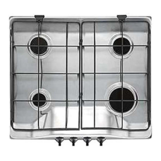
5. Technical Data Gas Burners Rating Rapid Burner (big) 2,9 kW Gas connection G 1/2" Semirapid Burner (medium) 1,9 kW Electric Supply 230 V 50 Hz Auxiliary Burner (small) 1,1 kW HOB RECESS Category II2HS3B/P DIMENSIONS Length 560 mm. Setting Natural Gas G 20 25 mbar Width 480 mm. -
Page 7: Electrical Connection
7. Electrical Connection The appliance is designed to be connected to 230 V monophase electricity supply. The connection must be carried out in compliance with the laws and regulations in force. Before the appliance is connected: 1) check that the main fuse and the domestic installation can support the load (see the rating label);... -
Page 8: Adaptation To Different Types Of Gas
8. Adaptation to different types of gas REPLACEMENT OF INJECTORS • Remove the pan supports. • Remove the burner's caps and crowns. • With a socket spanner 7 unscrew and remove the injectors (Fig. 9), and replace them with the ones required for the type of gas in use (see table on the next page). -
Page 9: Building In
BURNERS TYPE TYPE OF INJECTORS NOMINAL REDUCED NOMINAL NOMINAL OF GAS BURNER MARKS POWER POWER POWER PRESSURE 1/100 mm INPUT mbar Rapid (large) 0,65 0,276 NATURAL Semi-rapid (medium) 0,45 0,180 G 20 Auxiliary (small) 0,33 0,104 Rapido (grande) 0,65 Buthane Semirapido (medio) 0,45 G 30... - Page 10 FITTING THE LID We recommend the lid hinge block are fitted before installing the hob into the worktop. To install the lid onto the hob, proceed as follows: a. Remove the right and left hand grid blocks fitted to the back of the hob, by unscrewing the relevant screws (fig.
- Page 11 INSTALLATION AND ASSEMBLY These hobs can be installed in a kitchen unit with an opening for insertion whose dimensions are shown in Fig. 15. The edge of the cut out must have a minimum distance from the rear wall of 55 mm. If there are side walls, or sides of the furniture unit near the hob, the cut out edges must have a minimum distance of 100 mm.
- Page 12 POSSIBILITIES FOR Fig. 19 Fig. 18 INSERTION Kitchen unit with door Proper arrangements must be taken in designing the forniture unit, in order to avoid any contact with the bottom of the hob which can be heated when it is operated. The recommended solution is shown in Fig.