Husqvarna 1130SBEXP Owner's Manual
Walk-behind snow throwers
Hide thumbs
Also See for 1130SBEXP:
- Owner's manual (32 pages) ,
- Illustrated parts list (14 pages) ,
- Owner's manual (32 pages)
Table of Contents
Advertisement
Advertisement
Table of Contents

Related Manuals for Husqvarna 1130SBEXP


Summary of Contents for Husqvarna 1130SBEXP
- Page 1 1130SBEXP Owner's Manual / 96193001803...
-
Page 2: Safety Rules
IMPORTANT Safe Operation Practices for Walk-Behind Snow Throwers This snow thrower is capable of amputating hands and feet and throwing objects. Failure to observe the following safety instructions could result in serious injury. WARNING: Snow throwers have ex- Look for this symbol to point out im- posed rotating parts, which can cause por tant safety precautions. -
Page 3: Table Of Contents
Clearing a Clogged Discharge Chute 6. When cleaning, repairing or inspecting the snow thrower, stop the engine and make certain the col- Hand contact with the rotating impeller inside the discharge lector/impeller and all moving parts have stopped. chute is the most common cause of injury associated Disconnect the spark plug wire and keep the wire away with snow throwers. - Page 4 PARTS PACKED SEPARATELY IN CARTON...
-
Page 5: Assembly / Pre-Operation
ASSEMBLY / PRE-OPERATION Read these instructions and this manual in its entirety before you attempt to assemble or operate your new snow thrower. Reading the entire manual will familiarize you with the unit, which will assist you in assembly, operation and maintenance of the product. Your new snow thrower has been as sem bled at the factory with the ex cep tion of those parts left unassembled for shipping purposes. - Page 6 ASSEMBLY / PRE-OPERATION INSTALL TRACTION DRIVE CONTROL ROD INSTALL AUGER CONTROL ROD (See Figs. 5 and 6) (See Figs. 3 and 4) The auger control rod has the short loop on the end of the spring as shown. The traction drive control rod has the long loop on the end of the spring as shown.
- Page 7 ASSEMBLY / PRE-OPERATION INSTALL CHUTE DEFLECTOR REMOTE CONTROL INSTALL DISCHARGE CHUTE / CHUTE ROTATER (See Figs. 8 and 9) HEAD (See Fig. 7) 1. Install remote cable bracket to discharge chute with NOTE: The multi-wrench provided in your parts bag may 5/16-18 carriage bolt and 5/16-18 locknut as shown.
-
Page 8: Operation
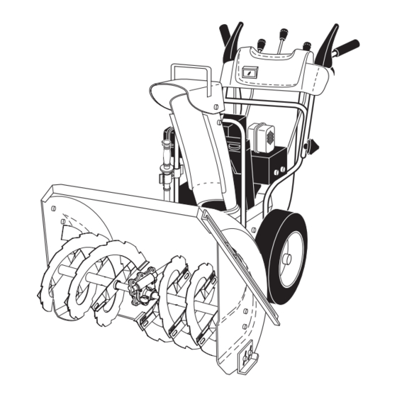
OPERATION KNOW YOUR SNOW THROWER READ THIS OWNER'S MANUAL AND ALL SAFETY RULES BEFORE OPERATING YOUR SNOW THROWER. Compare the illustrations with your snow thrower to familiarize yourself with the location of various controls and adjustments. Save this manual for future reference. These symbols may appear on your snow thrower or in literature supplied with the product. - Page 9 OPERATION SPARK ENGINE OIL CAP AUGER DISCHARGE CHUTE CONTROL LEVER PLUG WITH DIPSTICK CONTROL SAFETY LEVER TRACTION DRIVE SPEED IGNITION DRIVE CON TROL LEVER CONTROL GAS O LINE LEVER FILLER CHUTE CHOKE DE FLEC TOR CON- TROL FUEL SHUT-OFF LH TURN VALVE TRIGGER THROTTLE /...
- Page 10 OPERATION The operation of any snow thrower can result TO USE CHOKE CON TROL (See Fig. 13) in foreign objects thrown into the eyes, which The choke con trol is located on the en gine. Use the choke can result in severe eye damage. Always wear control when ev er you are starting a cold en gine.
- Page 11 OPERATION TO MOVE FORWARD AND BACKWARD (See Fig. 17) TO THROW SNOW (See Fig. 15) SELF-PROPELLING, forward and reverse movement of The auger rotation is controlled by the auger control lever located on the right side handle. the snow thrower, is controlled by the traction drive control lever located on the left side handle.
-
Page 12: Before Starting The Engine
OPERATION • When not using drift cutters, loosen adjustment nut, TO ADJUST SKID PLATES (See Fig. 19) lower to storage position and tighten nut securely. NOTE: The wrench provided in your parts bag may be used to adjust the skid plates. BEFORE STARTING THE ENGINE Skid plates are located on each side of the auger housing CHECK ENGINE OIL LEVEL (See Fig. -
Page 13: Snow Throwing Tips
OPERATION TO START ENGINE 6. When the engine starts, release the recoil starter han dle and slowly move the choke control to the OFF posi- • Be sure fuel shut-off valve is in the OPEN position. tion. Your snow thrower engine is equipped with both a 120 Volt Allow the engine to warm up for a few minutes. -
Page 14: Maintenance
MAINTENANCE GENERAL REC OM MEN DA TIONS LUBRICATION CHART ➀ The warranty on this snow thrower does not cover items SAE 5W-30 Motor Oil that have been sub ject ed to operator abuse or negligence. To receive full value from the warranty, operator must ➁... -
Page 15: Snow Thrower
MAINTENANCE SNOW THROWER Check the crankcase oil level before starting the engine and after each five (5) hours of continuous use. Tighten oil Always observe safety rules when performing main te nance. fill cap / dipstick securely each time you check the oil level. TIRES TO CHANGE ENGINE OIL •... -
Page 16: Service And Adjustments
SERVICE AND ADJUSTMENTS To replace the capscrew/shear bolts: WARNING: To avoid serious injury, before per- 1. Disengage all controls and move throttle control to forming any service or ad just ments: STOP position. Wait for all moving parts to stop. 1. -
Page 17: To Replace Belts
SERVICE AND ADJUSTMENTS TO REPLACE BELTS (See Fig. 24) HINT: Insert a 3/8" drive ratchet (in the “ON” position) into the square hole in idler arm and rotate ratchet clockwise The auger and traction drive belts are not adjustable. If to relieve tension. -
Page 18: Storage
TO REMOVE WHEELS (See Fig. 25) NOTE: To seal punctures or prevent flat tires due to slow leaks, tire sealant may be purchased from your local parts • Remove the klik pin and remove wheel from axle. dealer. Tire sealant also prevents tire dry rot and cor ro sion. IMPORTANT: When installing wheel, be sure to use the axle hole closest to the end of the shaft –... -
Page 19: Troubleshooting
TROUBLESHOOTING See appropriate section in manual unless directed to a qualified service center. PROBLEM CAUSE CORRECTION Does not start 1. Fuel shut-off valve (if so 1. Turn fuel shut-off valve to OPEN position. equipped) in OFF position. 2. Safety ignition key 2. - Page 20 AUGER HOUSING / IMPELLER ASSEMBLY REPAIR PARTS SNOW THROWER - MODEL NO. 1130SBEXP (96193001803), PRODUCT NO. 961 93 00-18...
-
Page 21: Repair Parts
AUGER HOUSING / IMPELLER ASSEMBLY REPAIR PARTS SNOW THROWER - MODEL NO. 1130SBEXP (96193001803), PRODUCT NO. 961 93 00-18 KEY PART KEY PART DESCRIPTION DESCRIPTION 532 18 25-16 Bar, Weight 532 18 79-25 Bearing, Auger 532 75 11-53 Nut, Hex 5/16-18... - Page 22 CONTROL PANEL / DISCHARGE CHUTE REPAIR PARTS SNOW THROWER - MODEL NO. 1130SBEXP (96193001803), PRODUCT NO. 961 93 00-18...
- Page 23 CONTROL PANEL / DISCHARGE CHUTE REPAIR PARTS SNOW THROWER - MODEL NO. 1130SBEXP (96193001803), PRODUCT NO. 961 93 00-18 KEY PART DESCRIPTION 532 41 42-80 Knob, Lever 817 50 10-10 Screw #10-24 x 5/8 532 19 84-75 Control Assembly, Deflector...
- Page 24 HANDLES REPAIR PARTS SNOW THROWER - MODEL NO. 1130SBEXP (96193001803), PRODUCT NO. 961 93 00-18...
- Page 25 HANDLES REPAIR PARTS SNOW THROWER - MODEL NO. 1130SBEXP (96193001803), PRODUCT NO. 961 93 00-18 KEY PART DESCRIPTION 532 41 55-42 Lever, Auger Control, RH 532 41 55-41 Lever, Traction Drive Control, LH 532 16 96-75 Retainer, Hairpin 817 06 04-08 Screw, Hex Head...
- Page 26 DRIVE REPAIR PARTS SNOW THROWER - MODEL NO. 1130SBEXP (96193001803), PRODUCT NO. 961 93 00-18 9 10 Drive 2006...
- Page 27 DRIVE REPAIR PARTS SNOW THROWER - MODEL NO. 1130SBEXP (96193001803), PRODUCT NO. 961 93 00-18 KEY PART DESCRIPTION 532 75 11-53 Nut, Lock 5/16-18 817 49 05-08 Screw, Hex Head 5/16-18 x 1/2 532 18 00-17 Bearing, Flange 532 18 01-34 Shaft, Auxiliary...
- Page 28 CHASSIS / ENGINE / PULLEYS REPAIR PARTS SNOW THROWER - MODEL NO. 1130SBEXP (96193001803), PRODUCT NO. 961 93 00-18 10 21 6 40...
- Page 29 CHASSIS / ENGINE / PULLEYS REPAIR PARTS SNOW THROWER - MODEL NO. 1130SBEXP (96193001803), PRODUCT NO. 961 93 00-18 KEY PART KEY PART DESCRIPTION DESCRIPTION 532 18 10-44 Spring, Traction Idler 532 85 10-84 Screw, Hex Head 3/8-24 x 1-3/8...
- Page 30 WHEELS / DECALS REPAIR PARTS SNOW THROWER - MODEL NO. 1130SBEXP (96193001803), PRODUCT NO. 961 93 00-18 15 12...
- Page 31 WHEELS / DECALS REPAIR PARTS SNOW THROWER - MODEL NO. 1130SBEXP (96193001803), PRODUCT NO. 961 93 00-18 KEY PART DESCRIPTION 532 19 95-21 Wheel Assembly, 16", Power Steering, LH 532 15 54-43 Pin, Klik 1/4 532 40 51-61 Cover, Power Steering...
-
Page 32: Warranty
532 41 51-89 09.07.07 TH Printed in U.S.A.