Central Machinery 93762 Assembly And Operating Instructions Manual
Harbor freight tools horizontal/vertical metal cutting bandsaw assembly and operating instructions 93762
Hide thumbs
Also See for 93762:
- Set up and operating instructions manual (29 pages) ,
- Owner's manual & safety instructions (28 pages)
Advertisement
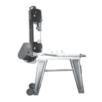
HORIZONTAL/VERTICAL
METAL CUTTING BANDSAW
Model 93762
ASSEMBLY AND OPERATING INSTRUCTIONS
Due to continuing improvements, actual product may differ slightly from the product described herein.
®
3491 Mission Oaks Blvd., Camarillo, CA 93011
Visit our Web site at: http://www.harborfreight.com
TO PREVENT SERIOUS INJURY,
READ AND UNDERSTAND ALL WARNINGS
AND INSTRUCTIONS BEFORE USE.
©
®
Copyright
2006 by Harbor Freight Tools
. All right reserved. No portion of this
manual or any artwork contained herein may be reproduced in any shape or form
without the express written consent of Harbor Freight Tools.
For technical questions, please call 1-800-444-3353.
Advertisement
Table of Contents

Related Manuals for Central Machinery 93762


Summary of Contents for Central Machinery 93762
- Page 1 2006 by Harbor Freight Tools . All right reserved. No portion of this manual or any artwork contained herein may be reproduced in any shape or form without the express written consent of Harbor Freight Tools. For technical questions, please call 1-800-444-3353.
-
Page 2: Product Specifications
Keep bystanders, children, and visitors away while operating a power tool. Distractions can cause you to lose control. Protect others in the work area from debris such as chips and sparks. Provide barriers or shields as needed. SKU 93762 For technical questions, please call 1-800-444-3353. PRODUCT SPECIFICATIONS... - Page 3 Dress properly. Do not wear loose clothing or jewelry. Contain long hair. Keep your hair, clothing, and gloves away from moving parts. Loose clothes, jewelry, or long hair can be caught in moving parts. SKU 93762 For technical questions, please call 1-800-444-3353. ELECTRICAL SAFETY...
- Page 4 If damaged, have the tool serviced before using. Many accidents are caused by poorly main- tained tools. SKU 93762 For technical questions, please call 1-800-444-3353. TOOL USE AND CARE Page 4...
-
Page 5: Specific Safety Rules
Maintain labels and nameplates on the Bandsaw. These carry important information. If unreadable or missing, contact Harbor Freight Tools for a replacement. Always wear safety impact eye goggles when using the Bandsaw. - Page 6 Allow the Saw Blade to rotate to full speed before feeding a workpiece into the Blade. When turning off the Bandsaw, allow the Saw Blade to spin down and stop on its own. Do not press against the Saw Blade to stop it.
- Page 7 Keep all safety guards in place and in proper working order. This Bandsaw is designed for indoor use only. CAUTION: If the teeth of the Saw Blade are so far apart that they straddle the workpiece, severe damage to the workpiece and/or Saw Blade will result.
- Page 8 The plug and outlet should look like those in the following illustration. (See Figure A.) THIS PRODUCT 3-PRONG PLUG FIGURE A SKU 93762 For technical questions, please call 1-800-444-3353. GROUNDING WARNING! USES A...
-
Page 9: Extension Cords
(See Figures C and D, next page.) If you are using an extension cord outdoors, make sure it is marked with the suffix “W-A” (“W” in Canada) to indicate it is acceptable for outdoor use. SKU 93762 For technical questions, please call 1-800-444-3353. EXTENSION CORDS... - Page 10 RECOMMENDED MINIMUM WIRE GAUGE FOR EXTENSION CORDS* FIGURE C FIGURE D SKU 93762 For technical questions, please call 1-800-444-3353. (120 VOLT) * Based on limiting the line voltage drop to five volts at 150% of the rated amperes.
-
Page 11: Assembly Instructions
When unpacking, check to make sure all the parts shown on the Parts Lists on pages 31 and 32 are included. If any parts are missing or broken, please call Harbor Freight Tools at the number shown on the cover of this manual as soon as possible. - Page 12 Machine Bed (142), and secure the Shaft by tightening the Hex Bolt (149). (See Figure G, next page.) Slide the Stock Stop (157) onto the Shaft (158), and secure by tightening the Socket Head Screw (156). (See Figure G.) SKU 93762 For technical questions, please call 1-800-444-3353. SCREW (59) SPRING WASHER (58)
- Page 13 Spindle Pulley to the Worm Shaft, using one Socket Head Screw (2). (See Figure I, next page. Insert the Shaft Key (80) in the slot on the Motor Shaft (81). Align the slot in the SKU 93762 For technical questions, please call 1-800-444-3353. HEX BOLT (149)
- Page 14 To Adjust The Cutting Speed: The Bandsaw is designed to cut at three different speeds: 80, 120, and 200 FPM (Feet Per Minute) depending on the type of material being cut. SKU 93762 For technical questions, please call 1-800-444-3353. SHAFT KEY (80)
- Page 15 LARGE MEDIUM SMALL WARNING! Always securely close the Lid on the Pulley Cover (72) after installing a V-Belt (10) or adjusting the cutting speed. SKU 93762 For technical questions, please call 1-800-444-3353. BELT GROOVE USED SPEED (SFM) SPINDLE PULLEY 80 FPM...
- Page 16 NOTE: Notching, slitting, and contour work is best done with the Bandsaw in its vertical position. Raise the Saw Head to its full vertical position, making sure it locks in position by turning the Support Plate (150) to the right until it firmly locks into the Body Frame (60) and inserting the Locking Pin (153).
-
Page 17: Operating Instructions
Clamp the workpiece firmly with the Moveable Vise Plate (141) by rotating the Hand Wheel (171) clockwise. (See Figure P.) HAND WHEEL (171) SKU 93762 For technical questions, please call 1-800-444-3353. MOVEABLE VISE PLATE (141) MACHINE BED (142) FIGURE O... - Page 18 Shaft (158). (See Figure R.) Adjust the Stock Stop (157) to the desired length position. Then, re-tighten the Socket Head Screw (156). (See Figure R.) SOCKET HEAD SCREW (156) SHAFT (158) SKU 93762 For technical questions, please call 1-800-444-3353. THREADED HOLE POSITION ANGLE SCALE...
- Page 19 NOTE: Blade Guide Bearings (88, 92, 100, 104) adjustment is a critical factor in the performance of the Bandsaw. It is always best to try a new Saw Blade (82) to see if it will correct poor cutting before attempting to adjust the Blade Guide Bearings. For example, if a Saw Blade becomes dull on one side sooner than the other, it will begin cutting crooked.
- Page 20 Adjusting The Blade Tracking: Raise the Saw Head to its full vertical position, making sure it locks in position by turning the Support Plate (150) to the right until it firmly locks into the Body Frame (60) and inserting the Locking Pin (153). (See Figure M.) Turn on the Bandsaw.
- Page 21 (127) clockwise to decrease the feed rate or counterclockwise to increase the feed rate. Do not turn the Handle more than one turn at a time. Excessive feed pressure can break the Saw Blade (82). Insufficient feed pressure dulls the Saw Blade rapidly. (See Figure U.)
- Page 22 Body Frame and inserting the Locking Pin (153). (See Figure W, next page.) Once all necessary adjustments to the Bandsaw have been made, plug the Power Cord Plug into the nearest 120 volt, grounded, electrical outlet. SKU 93762 For technical questions, please call 1-800-444-3353. (90, 102)
- Page 23 When cutting a large workpiece, make sure its entire length is properly sup- ported. If necessary, use a roller stand (not included) with a larger workpiece. Allow the Saw Blade (82) to turn up to full speed before feeding the workpiece into the Saw Blade. (See Figure W.) WARNING! Always keep hands and fingers safety away from the cutting area.
- Page 24 Once the cut is made, turn the Power Switch (164) to its “OFF” position. Then, unplug the Power Cord Plug from its electrical outlet. (See Figure W.) Wait until the Saw Blade (82) comes to a complete stop. Then, remove the work- piece and scrap material from the Vertical Cutting Plate (189).
- Page 25 (82) tension or machine vibration. If this is found, turn off the Bandsaw and correct the problem before using. (See Figure X.) Allow the Saw Blade (82) to turn up to full speed before feeding the Saw Blade into the workpiece. (See Figure X.) WARNING! Always keep hands and fingers safety away from the cutting area.
- Page 26 If abnormal noise or vibration occurs, have the problem corrected before further use. Do not use damaged equipment. Before each use, inspect the Saw Blade (82). Using a dull Saw Blade will cause excessive wear on the Motor of the Bandsaw and will not produce a satisfactory cut.
- Page 27 F. NOTE: The Bandsaw is equipped with a 64” diameter, .025” thick, 15/32” wide, 14 teeth per inch Saw Blade (82). The machine will also accept Blades in 4, 6, 8, and 10 tooth sizes. The choice of Blade pitch is determined by the thick- ness of the material to be cut.
- Page 28 (11) To clean the exterior parts of the Bandsaw, use only a clean cloth and mild detergent or mild solvent to clean the body of the Saw. Do not immerse any electrical part of the machine in any liquids. When the Bandsaw is not in use or when transporting the tool: Always lower...
- Page 29 LIABILITY ARISING OUT OF HIS OR HER REPAIRS TO THE ORIGINAL PRODUCT OR REPLACEMENT PARTS THERETO, OR ARISING OUT OF HIS OR HER INSTAL- LATION OF REPLACEMENT PARTS THERETO. SKU 93762 For technical questions, please call 1-800-444-3353. LOCKING PIN (115)
-
Page 30: Troubleshooting
SKU 93762 For technical questions, please call 1-800-444-3353. TROUBLESHOOTING (See Page 19.) (See Page 26.) (See Page 17.) (See Page 26.) (See Page 28.) (See Page 20.) (See Page 15.) (See Page 20.) (See Page 27.) (See Page 27.) (See Page 27.) (See Page 15.) -
Page 31: Parts List
Spring Washer (5) Screw (M5x8) Body Frame Some parts are listed and shown for illustration purposes only, and are not available individually as replacement parts. SKU 93762 For technical questions, please call 1-800-444-3353. PARTS LIST Part # Hex Head Bolt (M12x30) - Page 32 Screw (M6x8) Socket Head Screw (M8x8) Stock Stop Some parts are listed and shown for illustration purposes only, and are not available individually as replacement parts. SKU 93762 For technical questions, please call 1-800-444-3353. PARTS LIST (CONT.) Part # Shaft...
-
Page 33: Assembly Diagram
ASSEMBLY DIAGRAM 194: Vertical Cutting Plate Support Not Shown. NOTE: Some parts are listed and shown for illustration purposes only, and are not available individually as replacement parts. SKU 93762 For technical questions, please call 1-800-444-3353. Page 33...