Table of Contents
Advertisement
Chapter 1. Getting
Started
Getting Started
Thank you for purchasing the MD-5000 M-ATX
mainboard. The MD-5000 mainboard is based on SiS
North Bridge & 963 South Bridge chipsets for optimal system
efficiency. Designed to fit the advanced Intel
processors in the 478 pin package, the MD-5000
mainboard delivers a high performance and professional desktop
platform solution.
Information in this document is subject to change without
Medion® shall not be liable for errors contained herein or for
incidental or consequential damages in connection with the
furnishing, performance, or use of this material.
Pentium 4/Celeron
®
notice.
Getting Started
648
®
1-1
Advertisement
Table of Contents

Related Manuals for MSI MD 5000


Summary of Contents for MSI MD 5000
-
Page 1: Chapter 1. Getting
Getting Started Chapter 1. Getting Started Getting Started Thank you for purchasing the MD-5000 M-ATX mainboard. The MD-5000 mainboard is based on SiS ® North Bridge & 963 South Bridge chipsets for optimal system efficiency. Designed to fit the advanced Intel Pentium 4/Celeron ®... -
Page 2: Mainboard Specifications
MD5000 M-ATX Mainboard Mainboard Specifications Supports Socket 478 for P4/Celeron processors (Willimate and Northwood core) with 400/533 MHz Core Frequency from 1.3 GHz to 2.8 GHz and up Chipset 648 chipset ® - Supports Intel Pentium 4 processors with data transfer rate up to 533 MHz - Supports 64-bit high performance DDR333+/DDR333/DDR266 memory controller - Supports AGP 8X/4X interface... - Page 3 Getting Started - 1 parallel port - Audio * 3 in vertical for 6 channels Line-out, 2 in vertical for MIC & Line- - 1 standard 1394 connector - 1 mini 1394 connector - 5 USB ports (3 front + 2 rear) - 1 RJ-45 Lan Jack (optional) - PS2 KB/Mouse Onboard IEEE1394...
-
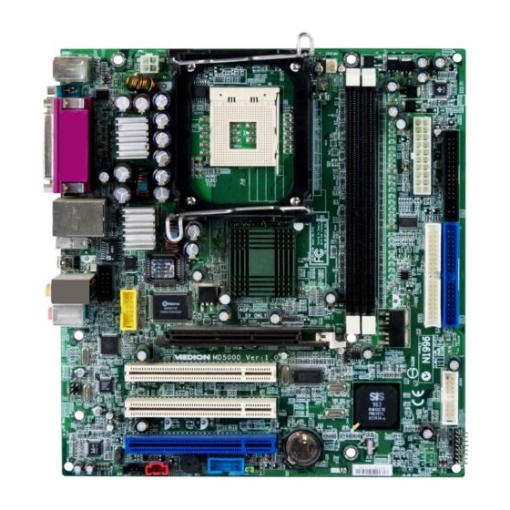
Page 4: Mainboard Layout
MD-5000 M-ATX Mainboard Mainboard Layout Top : mouse Bottom: keyboard JPW1 CPUFAN1 Top : LPT Bottom: COM A SPDIF in SPDIF out T: RJ45 LAN jack B: USB ports IEEE1394 Port Mini IEEE 1394 Port BIOS 6-Channel Line-out Winbond 83697HF Line-in AGP Slot AGERE... -
Page 5: Chapter 2. Hardware
Hardware Setup Chapter 2. Hardware Setup Hardware Setup This chapter tells you how to install the CPU, memory modules, and expansion cards, as well as how to setup the jump- ers on the mainboard. Also, it provides the instructions on con- necting the peripheral devices, such as the mouse, keyboard, etc. -
Page 6: Quick Components Guide
MD-5000 M-ATX Mainboard Quick Components Guide JPW1, p.2-9 CPU, p.2-3 CPUFAN1, p.2-17 DDR DIMMs, p.2-7 CONN1, p.2-9 Back Panel FDD1, p.2-15 I/O, p.2-10 J7, p.2-26 IDE1 & IDE2 p.2-16 J9, p.2-26 AGP Slot, p.2-28 JSPDIF1, p.2-23 JUSB1, p.2-27 F_P1, p.2-17 JCD1, p.2-25 PCI Slots, p.2-28 JBAT1, p.2-25... -
Page 7: Central Processing Unit (Cpu)
CPU core speed Host Clock x Core/Bus ratio 100MHz x 14 1.4 GHz MSI Reminds You... Overheating Overheating will seriously damage the CPU and system, al- ways make sure the cooling fan can work properly to protect the CPU from overheating. -
Page 8: Cpu Installation Procedures For Socket 478
MD-5000 M-ATX Mainboard CPU Installation Procedures for Socket 478 Please turn off the power and unplug the power cord before Open Lever installing the CPU. Pull the lever sideways away Sliding 90 degree Plate from the socket. Make sure to raise the lever up to a 90- degree angle. - Page 9 Hardware Setup Memory The mainboard provides 2 slots for 184-pin DDR SDRAM DIMM (Double In-Line Memory Module) modules and supports the memory size up to 2GB. You can install DDR200/266/333 modules on the DDR DIMM slots (DIMM 1~2). DDR DIMM Slots (DDR 1~2)
-
Page 10: Dimm Module Combination
3. The plastic clip at each side of the DIMM slot will automatically close. Notch Volt MSI Reminds You... You can barely see the golden finger if the module is properly inserted in the socket. -
Page 11: Power Supply
Hardware Setup Power Supply The mainboard supports ATX power supply for the power system. Be- fore inserting the power supply connector, always make sure that all compo- nents are installed properly to ensure that no damage will be caused. ATX 20-Pin Power Connector: CONN1 This connector allows you to connect to an ATX power supply. -
Page 12: Back Panel
MD-5000 M-ATX Mainboard Back Panel The back panel provides the following connectors: 6 Channel L-out Parallel (Optional) Mouse L-in IEEE1394 Keyboard SPDIF- SPDIF- COM A Ports Mouse Connector The mainboard provides a standard PS/2 ® mouse mini DIN connector ® ®... -
Page 13: Keyboard Connector
Hardware Setup Keyboard Connector ® The mainboard provides a standard PS/2 keyboard mini DIN connec- ® ® tor for attaching a PS/2 keyboard. You can plug a PS/2 keyboard directly into this connector. Pin Definition SIGNAL DESCRIPTION Keyboard DATA Keyboard DATA No connection Ground Keyboard Clock... -
Page 14: Parallel Port Connector: Lpt1
MD-5000 M-ATX Mainboard Parallel Port Connector: LPT1 The mainboard provides a 25-pin female centronic connector as LPT. A parallel port is a standard printer port that supports Enhanced Parallel Port (EPP) and Extended Capabilities Parallel Port (ECP) mode. Pin Definition SIGNAL DESCRIPTION STROBE... -
Page 15: Lan Jack (Optional)
(rear speakers) Line-in Line-out (front speaker) MSI Reminds You... For advanced audio application, RealTek ALC650 audio chip is provided as an option to offer support for 6-channel audio operation and can turn rear audio connectors from 2-channel to 4-/6-channel audio. - Page 16 MD-5000 M-ATX Mainboard IEEE1394 Ports The mainboard provides two IEEE 1394 ports. The mini IEEE1394 port is designed for you to connect the IEEE1394 device with external power. The standard IEEE1394 port connects to IEEE1394 devices without external power. The IEEE1394 high-speed serial bus complements USB by providing enhanced PC connectivity for a wide range of devices, including consumer electronics audio/video (A/V) appliances, storage peripherals, other PCs, and portable devices.
-
Page 17: Serial Port Connector: Com A
Hardware Setup Serial Port Connector: COM A The mainboard offers one 9-pin male DIN connector as serial port COM A. The port is a 16550A high speed communication port that sends/receives 16 bytes FIFOs. You can attach a serial mouse or other serial devices directly to the connector. -
Page 18: Floppy Disk Drive Connector: Fdd1
MD-5000 M-ATX Mainboard Connectors The mainboard provides connectors to connect to FDD, IDE HDD, case, modem, LAN, USB Ports, IR module and CPU/System FAN. Floppy Disk Drive Connector: FDD1 The mainboard provides a standard floppy disk drive connector that supports 360K, 720K, 1.2M, 1.44M and 2.88M floppy disk types. FDD1 2-16... -
Page 19: Hard Disk Connectors: Ide1 & Ide2
IDE2 (Secondary IDE Connector) IDE2 can also connect a Master and a Slave drive. MSI Reminds You... If you install two hard disks on cable, you must configure the second drive to Slave mode by setting its jumper. Refer to the hard disk documentation supplied by hard disk vendors for jumper setting instructions. -
Page 20: Fan Power Connector: Cpufan1
CPU fan control. +12V SENSOR CPUFAN1 MSI Reminds You... 1. Always consult the vendors for proper CPU cooling fan. 2. CPUFAN supports the fan control. You can install the PC Alert utility that will automatically control the CPU fan speed according to the actual CPU temperature. - Page 21 Hardware Setup Front Panel Connector: F_P1 The mainboard provides one front panel connector for electrical con- nection to the front panel switches and LEDs. PS-ON PWR_LED HDD_LED Reset F_P1 2-19...
-
Page 22: Front Panel Audio Connector: Jaudio1
MIC_IN Line_Next_R MIC_IN_S Line_Next_L MSI Reminds You... If you don’t want to connect to the front audio header, pins 1 & 2, 3 & 4 have to be jumpered in order to have signal output directed to the rear audio ports. Otherwise, the Line-Out connector on the back panel will not function. -
Page 23: Front Usb Connector: Jusb1
Hardware Setup Front USB Connector: JUSB1 The mainboard provides one front Universal Serial Bus connector for users to connect USB devices. JUSB1 JUSB1 Pin Definition Description Description Power Power SGND SGND Power Power 2-21... -
Page 24: Cd-In Connector: Jcd1
MD-5000 M-ATX Mainboard CD-In Connector: JCD1 The connector is for CD-ROM audio connector. Audio Connector: JVEDIO1 This connector allows you to connect to a TV Tuner Card. JCD1 JVEDIO1 VIDEO-L VIDEO-R 2-22... -
Page 25: Spdif Connector: Jspdif1
Hardware Setup SPDIF Connector: JSPDIF1 The connector is used to connect an optional bracket for SPDIF (Sony & Philips Digital Interconnect Format) digital audio transmission. JSPDIF1 JSPDIF1 Pin Definition Description Description VCC5 VCC3 SPDIF-O SPDIF-I 2-23... - Page 26 MD-5000 M-ATX Mainboard IEEE 1394 Connector: J7 (Optional) The mainboard provides one IEEE1394 connector with housing that allows you to connect optional IEEE 1394 ports. Pin Definition SIGNAL SIGNAL IEGND TPA0- TPA0+ Power Power TPB0+ TPB0- IEGND 2-24...
- Page 27 Hardware Setup Joystick/Game Connector: J9 (Optional) You can connect a joystick or game pad to this connector. J9 Pin Definition Description Description FVCC5 (power) Key pin 2-25...
-
Page 28: Jumpers
Keep Data Clear Data JBAT1 MSI Reminds You... You can clear CMOS by shorting 2-3 pin while the system is off. Then return to 1-2 pin position. Avoid clearing the CMOS while the system is on; it will damage the mainboard. -
Page 29: Agp (Accelerated Graphics Port) Slot
Hardware Setup Slots The motherboard provides one AGP slot and three 32-bit PCI bus slots. AGP Slot PCI Slots PCI Combo Slot for the use of special combo cards AGP (Accelerated Graphics Port) Slot The AGP slot allows you to insert the AGP graphics card. AGP is an interface specification designed for the throughput demands of 3D graphics. -
Page 30: Pci Interrupt Request Routing
MD-5000 M-ATX Mainboard PCI Interrupt Request Routing The IRQ, acronym of interrupt request line and pronounced I-R-Q, are hardware lines over which devices can send interrupt signals to the microprocessor. The PCI IRQ pins are typically connected to the PCI bus INT A# ~ INT D# pins as follows: Order 1 Order 2...