Table of Contents
Advertisement
Quick Links
Quick Start
Thank you for purchasing the MSI
MEG X399 CREATION
motherboard. This Quick
®
Start section provides demonstration diagrams about how to install your computer.
Some of the installations also provide video demonstrations. Please link to the URL to
watch it with the web browser on your phone or tablet. You may have even link to the
URL by scanning the QR code
Preparing Tools and Components
AMD
Ryzen
®
Threadripper CPU
Thermal Paste
CPU Fan
DDR4 Memory
Power Supply Unit
Chassis
SATA DVD Drive
Graphics Card
SATA Hard Disk Drive
Phillips Screwdriver
A Package of Screws
Torqkey Screwdriver
1
Quick Start
Advertisement
Table of Contents

Related Manuals for MSI MEG X399 CREATION


Summary of Contents for MSI MEG X399 CREATION
-
Page 1: Quick Start
Quick Start Thank you for purchasing the MSI MEG X399 CREATION motherboard. This Quick ® Start section provides demonstration diagrams about how to install your computer. Some of the installations also provide video demonstrations. Please link to the URL to watch it with the web browser on your phone or tablet. -
Page 2: Installing A Processor
Installing a Processor https://youtu.be/yk4EpVUU03E Quick Start... -
Page 3: Installing Ddr4 Memory
Installing DDR4 memory http://youtu.be/T03aDrJPyQs Quick Start... -
Page 4: Connecting The Front Panel Header
Connecting the Front Panel Header http://youtu.be/DPELIdVNZUI HDD LED + Power LED + HDD LED - Power LED - Reset Switch Power Switch Reset Switch Power Switch JFP1 Reserved No Pin JFP1 HDD LED - HDD LED HDD LED + POWER LED - POWER LED POWER LED + Quick Start... -
Page 5: Installing The Motherboard
Installing the Motherboard If you want to use the mounting screw hole, please refer to M.2 SHIELD FROZR1 & M.2 SHIELD FROZR2 section for removing the M.2 SHIELD FROZR 2. Quick Start... -
Page 6: Installing Sata Drives
Installing SATA Drives http://youtu.be/RZsMpqxythc Quick Start... -
Page 7: Installing A Graphics Card
Installing a Graphics Card http://youtu.be/mG0GZpr9w_A Quick Start... -
Page 8: Connecting Peripheral Devices
Connecting Peripheral Devices Quick Start... -
Page 9: Connecting The Power Connectors
Connecting the Power Connectors http://youtu.be/gkDYyR_83I4 ATX_PWR1 CPU_PWR1~2 PCIE_PWR1 Quick Start... -
Page 10: Power On
Power On Quick Start... -
Page 11: Table Of Contents
Contents Quick Start ......................1 Preparing Tools and Components ................1 Installing a Processor ..................... 2 Installing DDR4 memory ..................3 Connecting the Front Panel Header ............... 4 Installing the Motherboard ..................5 Installing SATA Drives..................... 6 Installing a Graphics Card ..................7 Connecting Peripheral Devices ................ - Page 12 CPU_FAN1, PUMP_FAN1, SYS_FAN1~5, EXT_FAN1~3: Fan Connectors .... 47 T_SEN1~3: Thermal Sensor Connectors ............. 47 JCI1: Chassis Intrusion Connector ............... 48 JTPM1: TPM Module Connector ................48 JAUD1: Front Audio Connector ................49 JBAT1: Clear CMOS (Reset BIOS) Jumper ............49 JBLK_U1, JBLK_D1: Base clock Plus, Minus connectors ........
- Page 13 COMMAND CENTER ..................... 82 GAMING APP ......................86 X-BOOST ....................... 91 MYSTIC LIGHT ....................... 93 MYSTIC LIGHT PARTY ................... 97 SMART TOOL ....................... 101 RAMDISK......................103 GAMING LAN MANAGER ..................104 Nahimic 3 ......................106 Troubleshooting ....................109 Regulatory Notices .................... 110 Contents...
-
Page 14: Safety Information
Safety Information y The components included in this package are prone to damage from electrostatic discharge (ESD). Please adhere to the following instructions to ensure successful computer assembly. y Ensure that all components are securely connected. Loose connections may cause the computer to not recognize a component or fail to start. -
Page 15: Specifications
Memory 3066(OC)/ 2933(OC)/ 2800(OC)/ 2667(OC)/ 2667(by JEDEC)/ 2400(by JEDEC)/ 2133(by JEDEC) MHz* * For the latest information about memory, please visit http://www.msi.com ** Please refer the DIMM Slots section for more details. y 4x PCIe 3.0 x16 slots Expansion Slots y 1x PCIe 2.0 x1 slot... - Page 16 Continued from previous page y ASMedia ASM3142 Chipset ® ƒ 1x USB 3.1 Gen2 (SuperSpeed USB 10Gbps) Type-C port available through the internal USB connector y AMD X399 Chipset ® ƒ 1x USB 3.1 Gen1 (SuperSpeed USB) Type-A port on the back panel ƒ...
- Page 17 Continued from previous page y 1x 24-pin ATX main power connector y 2x 8-pin ATX 12V power connector y 1x flat 4-pin ATX 12V power connector* y 8x SATA 6Gb/s connectors y 2x USB 2.0 connectors (supports additional 4 USB 2.0 ports) y 2x USB 3.1 Gen1 connectors (supports additional 4 USB 3.1 Gen1 ports)
- Page 18 Software y MYSTIC LIGHT (LED) y RAMDISK y GAMING LAN MANAGER y Nahimic 3 y Open Broadcaster Software (OBS) y CPU-Z MSI GAMING y Norton™ Internet Security Solution y Google Chrome™ ,Google Toolbar, Google Drive Continued on next page Specifications...
- Page 19 Continued from previous page y Audio Boost 4 y Nahimic 3 y GAMING LAN with Gaming LAN Manager y Intel WiFi y Triple Turbo M.2 y Pump Fan y Smart Fan Control y Mystic Light y Mystic Light Extension y Mystic light SYNC y EZ DEBUG LED y DDR4 Steel Armor y M.2 Shield FROZR...
-
Page 20: Jcorsair1 Connector Specification
JCORSAIR1 Connector Specification Supporting CORSAIR RGB Products Maximum connection Lighting PRO RGB LED Strip HD RGB Fan SP RGB Fan LL RGB Fan Package contents Please check the contents of your motherboard package. It should contain: y User Manual y Quick Installation Guide y Driver DVD y SATA 6G Cable x4 y LED Y CABLE... -
Page 21: Block Diagram
Block Diagram 2/ 4 Channel DDR4 Memory Processor 3x M.2 PCI Express Bus 8x USB 3.1 Gen1 Realtek NV6797 ALC1220 Super I/O DMI 3.0 Audio Jacks PCIe x1 slot PCIE Bus 8x SATA 6Gb/s X399 Intel 9260 WiFi 4x USB 3.1 Gen1 2x USB 3.1 Gen1 4x USB 2.0 ASMEDIA... -
Page 22: Rear I/O Panel
Rear I/O Panel BIOS FLASHBACK+ port USB 3.1 Gen1 Audio Ports** Type-A** WiFi Antenna Connectors LAN* Clear CMOS button USB 3.1 Gen1 Type-A*** Optical S/PDIF-Out** BIOS USB 3.1 Gen1 Type-A** USB 3.1 Gen1 Type-C* FLASHBACK+ (VR READY ports) button USB 3.1 Gen1 Type-A* y Clear CMOS button - Power off your computer. -
Page 23: Installing Antennas
Installing Antennas 1. Combine the antenna with the base. 2. Screw two antenna cables tight to the WiFi antenna connectors as shown. 3. Place the antenna as high as possible. Rear I/O Panel... -
Page 24: Realtek Audio Console
Realtek Audio Console After Realtek Audio Console is installed. You can use it to change sound settings to get better sound experience. Application Enhancement Advanced Settings Device Selection Main Volume Jack Status Connector Settings y Device Selection - allows you to select a audio output source to change the related options. - Page 25 Audio jacks to headphone and microphone diagram Audio jacks to stereo speakers diagram AUDIO INPUT Audio jacks to 7.1-channel speakers diagram AUDIO INPUT Rear Front Side Center/ Subwoofer Rear I/O Panel...
-
Page 26: Overview Of Components
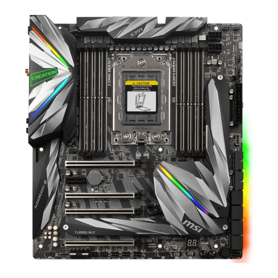
Overview of Components DIMMB2 DIMMB1 CPU_PWR1 CPU Socket DIMMA2 CPU_PWR2 CPU_FAN1 DIMMA1 PUMP_FAN1 JRGB2 T_SEN3 SYS_FAN5 DIMMC1 DIMMC2 SYS_FAN3 DIMMD1 JCORSAIR1 DIMMD2 ATX_PWR1 M2_3 JUSB3 JBLK_U1 SYS_FAN1 JBLK_D1 JUSB5 PCI_E1 JSLOW1 JCI1 PCI_E2 JUSB4 JBAT1 PCI_E3 SATA▼1▲2 JOC_RT1 PCI_E4 SATA▼3▲4 M2_1 JOC_FS1 M2_2... - Page 27 Component Contents Port Name Port Type Page CPU_FAN1, PUMP_FAN1, Fan Connectors SYS_FAN1~5, EXT_FAN1~3 CPU_PWR1~2, ATX_PWR1, Power Connectors PCIE_PWR1 CPU Socket Socket TR4 DIMMA1~DIMMD2 DIMM Slots JAUD1 Front Audio Connector JBAT1 Clear CMOS (Reset BIOS) Jumper Base clock Plus, Minus JBLK_U1, JBLK_D1 connectors JCI1 Chassis Intrusion Connector...
-
Page 28: Cpu Socket
CPU Socket Please use the Torx screwdriver come with the AMD CPU and follow the steps below to install the CPU. Video Demonstration Watch the video to learn how to unbox and install AMD Ryzen Threadripper CPU. https://youtu.be/yk4EpVUU03E 1. Loosen load plate screws with the AMD Torx screwdriver in the sequence 3→2→1. The load plate will automatically lift up to the fully open position. - Page 29 3. Remove the protective pin cap, and then close and buckle the frame rail. Protective pin cap 4. Close the load plate, and then turn the load plate screws clockwise a little with the AMD Torx screwdriver in the sequence 1→2→3→1→2→3 until they are snug. AMD Torx screwdriver 5.
- Page 30 Always unplug the power cord from the power outlet before installing or removing the CPU. Please retain the protective caps after installing the processor. MSI will deal with Return Merchandise Authorization (RMA) requests if only the motherboard comes with the protective caps on the CPU socket.
-
Page 31: Oc1: Game Boost Knob
OC1: GAME BOOST Knob This knob allows you to manually select a stage from number 0 (default) to number 11 (extreme) for overclocking the processor. The processor’ s voltage and frequency will be automatically adjusted after you power on your computer. GAME BOOST knob Using GAME BOOST Knob To setup the GAME BOOST knob, take the following steps:... -
Page 32: Joc_Rt1: Oc Retry Jumper
3. Rotate the GAME BOOST knob to 0 and then power on. The configuration parameters will be returned to default values. Important You can also control the GAME BOOST function in BIOS Setup or with MSI COMMAND CENTER software. In order to optimize performance and improve system stability, when you activate the GAME BOOST function, please leave the settings in the BIOS >... -
Page 33: Jslow1: Slow Mode Booting Jumper
JSLOW1: Slow Mode Booting Jumper This jumper is used for LN2 cooling solution, that provides the extreme overclocking conditions, to boot at a stable processor frequency and to prevent the system from crashing. Normal Enabled (default) (Please enable this jumper during BIOS POST.) Important Users will try extreme low temperature overclocking at their own risks. - Page 34 Memory module installation recommendation (For 2990WX processor only) CPU Socket 1 DIMM 2 DIMMs SocketTR4 CPU 3 DIMMs (2990WX) 4 DIMMs 8 DIMMs DIMMA2 DIMMC2 DIMMA2 DIMMB2 DIMMC2 DIMMA2 DIMMC2 DIMMB2 DIMMB2 DIMMC1 DIMMD2 DIMMA2 DIMMB1 DIMMC2 DIMMD1 DIMMA2 DIMMA1 DIMMD2 Overview of Components...
- Page 35 Memory module installation recommendation (Except 2990WX processor) CPU Socket 1 DIMM 2 DIMMs 3 DIMMs SocketTR4 CPU 4 DIMMs 8 DIMMs DIMMB2 DIMMD2 DIMMB2 DIMMB2 DIMMD2 DIMMA2 DIMMC2 DIMMB2 DIMMB2 DIMMC1 DIMMD2 DIMMA2 DIMMB1 DIMMC2 DIMMD1 DIMMA2 DIMMA1 DIMMD2 Overview of Components...
-
Page 36: Pci_E1~5: Pcie Expansion Slots
PCI_E1~5: PCIe Expansion Slots PCI_E1: PCIe 3.0 x16 PCI_E2: PCIe 2.0 x1 PCI_E3: PCIe 3.0 x8 PCI_E4: PCIe 3.0 x16 PCI_E5: PCIe 3.0 x8 Multiple graphics cards recommendation (For 2990WX processor only) Graphics Card Single 2-Way 3-Way PCI_E1 (CPU Die 1) PCI_E2 (Promontory) PCIe x1 slot PCI_E3 (CPU Die 1) - Page 37 PCI_E5 PCI_E4 Important If you install a large and heavy graphics card, you need to use a tool such as MSI Gaming Series Graphics Card Bolster to support its weight and to prevent deformation of the slot. When adding or removing expansion cards, always turn off the power supply and unplug the power supply power cable from the power outlet.
- Page 38 Installing SLI graphics cards For power supply recommendations for SLI configurations, please refer to the user guide of your graphics card to make sure you meet all the system requirements. To install SLI graphics cards: 1. Turn off your computer and disconnect the power cord, install two graphics cards into the PCI_E1 and PCI_E4 slots.
-
Page 39: M2_1~3: M.2 Slots (Key M)
M2_1~3: M.2 Slots (Key M) Video Demonstration Watch the video to learn how to Install M.2 device. http://youtu.be/JCTFABytrYA * For 2990WX processor, M2_1 and M2_2 M2_3 (Die 0) slots are controlled by Die1, and M2_3 is M2_1 (Die 1) controlled by Die0. M2_2 (Die 1) M.2 SHIELD FROZR1 &... - Page 40 Installing M.2 device 1. Loosen the M.2 riser screw from the 3. Insert your M.2 SSD into the M.2 motherboard. slot at a 30-degree angle. 2. Move and fasten the M.2 riser screw to 4. Secure the M.2 SSD in place with the appropriate location for your M.2 the supplied M.2 screw.
-
Page 41: Installing M.2 Xpander-Aero Card
Installing M.2 XPANDER-AERO card The M.2 XPANDER-AERO card provide four M.2 Key-M slots. To install the M.2 XPANDER-AERO card, please follows the steps below: 1. Remove the heatsink by loosening four heatsink screws on the bottom of M.2 XPENDER-AERO. 2. Loosen the M.2 screw from the base screw. 3. - Page 42 9. Insert the M.2 XPENDER-AERO into an PCIe x16 slot (PCI_E1 or PCI_E4). 10. Use the screw to secure the M.2 XPENDER-AERO. 11. Connect the PCIE_PWR1 connector to the power supply. 12. Connect the case’ s HDD LED cable to the JCASE connector. 13.
-
Page 43: Sata1~8: Sata 6Gb/S Connectors
SATA1~8: SATA 6Gb/s Connectors These connectors are SATA 6Gb/s interface ports. Each connector can connect to one SATA device. SATA2 SATA1 SATA4 SATA3 SATA6 SATA5 SATA8 SATA7 Important Please do not fold the SATA cable at a 90-degree angle. Data loss may result during transmission otherwise. -
Page 44: Cpu_Pwr1~2, Atx_Pwr1, Pcie_Pwr1: Power Connectors
CPU_PWR1~2, ATX_PWR1, PCIE_PWR1: Power Connectors These connectors allow you to connect an ATX power supply. CPU_PWR1/ CPU_PWR2 Ground +12V Ground +12V Ground +12V Ground +12V +3.3V +3.3V +3.3V -12V Ground Ground PS-ON# Ground Ground Ground ATX_PWR1 Ground Ground PWR OK 5VSB +12V +12V... -
Page 45: Jusb1~2: Usb 2.0 Connectors
JUSB1~2: USB 2.0 Connectors These connectors allow you to connect USB 2.0 ports on the front panel. USB0- USB1- USB0+ USB1+ Ground Ground No Pin Important Note that the VCC and Ground pins must be connected correctly to avoid possible damage. -
Page 46: Jusb3: Usb 3.1 Gen2 Type-C Connector
However, when you boot the computer into Windows ® you will need to install the MSI SUPER CHARGER application to turn ON/OFF the ®... -
Page 47: Cpu_Fan1, Pump_Fan1, Sys_Fan1~5, Ext_Fan1~3: Fan Connectors
CPU_FAN1, PUMP_FAN1, SYS_FAN1~5, EXT_FAN1~3: Fan Connectors Fan connectors can be classified as PWM (Pulse Width Modulation) Mode or DC Mode. PWM Mode fan connectors provide constant 12V output and adjust fan speed with speed control signal. DC Mode fan connectors control fan speed by changing voltage. This motherboard can automatically detect PWM and DC mode. -
Page 48: Jci1: Chassis Intrusion Connector
JCI1: Chassis Intrusion Connector This connector allows you to connect the chassis intrusion switch cable. Normal Trigger the chassis (default) intrusion event Using chassis intrusion detector 1. Connect the JCI1 connector to the chassis intrusion switch/ sensor on the chassis. 2. -
Page 49: Jaud1: Front Audio Connector
JAUD1: Front Audio Connector This connector allows you to connect audio jacks on the front panel. MIC L Ground MIC R Head Phone R MIC Detection SENSE_SEND No Pin Head Phone L Head Phone Detection JBAT1: Clear CMOS (Reset BIOS) Jumper There is CMOS memory onboard that is external powered from a battery located on the motherboard to save system configuration data. -
Page 50: Jblk_U1, Jblk_D1: Base Clock Plus, Minus Connectors
JBLK_U1, JBLK_D1: Base clock Plus, Minus connectors You can use these connectors to connect the external buttons. Press the button connecting to JBLK_U1 to increase the CPU base clock or press the button connecting to JBLK_D1 to decrease the CPU base clock. JBLK_D1 (short the jumper to decrease the CPU base clock) JBLK_U1... -
Page 51: Jrgb1, Jrgb2, Jrainbow1: Rgb Led Connectors
Addressable RGB LED strips (5V/Data/Ground) with the maximum power rating of 3A (5V). Always turn off the power supply and unplug the power cord from the power outlet before installing or removing the RGB LED strip. Please use MSI’ s software to control the extended LED strip. Overview of Components... -
Page 52: Jcorsair1: Corsair Connector
Addressable Lighting PRO RGB LED strips 5V or CORSAIR RGB fans with the CORSAIR fan hub. Once all items are connected properly, you can control the CORSAIR RGB LED strips and fans with MSI's software. Data CORSAIR RGB Fan Connection... -
Page 53: Onboard Leds
Onboard LEDs EZ Debug LED These LEDs indicate the debug status of the motherboard. CPU - indicates CPU is not detected or fail. DRAM - indicates DRAM is not detected or fail. VGA - indicates GPU is not detected or fail. BOOT - indicates the booting device is not detected or fail. -
Page 54: Jpwrled1: Led Light Demonstration Power Input Connector
JPWRLED1: LED light demonstration power input connector This connector is used by retailers to demonstrate onboard LED lights. JPWRLED1 - LED power input Debug Code LED The Debug Code LED displays progress and error codes during and after POST. Refer to the Debug Code LED table for details. -
Page 55: Debug Code Led Table
Debug Code LED Table CPU post-memory initialization. Application Processor(s) (AP) SEC Progress Codes initialization CPU post-memory initialization. Boot Power on. Reset type detection (soft/ Strap Processor (BSP) selection hard) CPU post-memory initialization. System AP initialization before microcode loading Management Mode (SMM) initialization System Agent initialization before Post-Memory System Agent initialization microcode loading... - Page 56 PCI Bus Enumeration 32 PCI resource allocation error. Out of Resources PCI Bus Request Resources No Space for Legacy Option ROM PCI Bus Assign Resources No Console Output Devices are found Console Output devices connect No Console Input Devices are found Console input devices connect Invalid password Super IO Initialization...
-
Page 57: Acpi States Codes
ACPI States Codes The following codes appear after booting and the operating system into ACPI modes. System is entering S1 sleep state System is entering S2 sleep state System is entering S3 sleep state System is entering S4 sleep state System is entering S5 sleep state System is waking up from the S1 sleep state... -
Page 58: Bios Setup
BIOS Setup The default settings offer the optimal performance for system stability in normal conditions. You should always keep the default settings to avoid possible system damage or failure booting unless you are familiar with BIOS. Important BIOS items are continuously update for better system performance. Therefore, the description may be slightly different from the latest BIOS and should be for reference only. -
Page 59: Resetting Bios
Updating BIOS Updating BIOS with M-FLASH Before updating: Please download the latest BIOS file that matches your motherboard model from MSI website. And then save the BIOS file into the USB flash drive. Updating BIOS: 1. Press Del key to enter the BIOS Setup during POST. - Page 60 Before updating: Please download the latest BIOS file that matches your motherboard model from MSI ® website and rename the BIOS file to MSI.ROM. And then, save the MSI.ROM file to the root of USB flash drive. Important Only the FAT32 format USB flash drive supports updating BIOS by BIOS FLASHBACK+.
-
Page 61: Ez Mode
EZ Mode At EZ mode, it provides the basic system information and allows you to configure the basic setting. To configure the advanced BIOS settings, please enter the Advanced Mode by pressing the Setup Mode switch or F7 function key. A-XMP switch Setup Mode switch Screenshot... - Page 62 y Information display - click on the CPU, Memory, Storage, Fan Info and Help buttons on left side to display related information. y Function buttons - enable or disable the LAN Option ROM, HD audio controller, AHCI/RAID, CPU Fan Fail Warning Control, Windows 10 WHQL support and BIOS Log Review by clicking on their respective button.
-
Page 63: Advanced Mode
Advanced Mode Press Setup Mode switch or F7 function key can switch between EZ Mode and Advanced Mode in BIOS setup. A-XMP switch Setup Mode switch Screenshot Search Language System information GAME BOOST switch Boot device priority bar BIOS menu BIOS menu selection selection... -
Page 64: Settings
SETTINGS System Status f System Date Sets the system date. Use tab key to switch between date elements. The format is <day> <month> <date> <year>. <day> Day of the week, from Sun to Sat, determined by BIOS. Read-only. <month> The month from Jan. through Dec. <date>... - Page 65 Allows you to utilize more than 4x GPUs. [Disabled] Disables this function. fPCIe SlotX Lanes Configuration PCIe lanes configuration for MSI M.2 XPANDER series cards/ Other M.2 PCIe storage card. f ACPI Settings Sets ACPI parameters of onboard power LED behaviors. Press Enter to enter the sub- menu.
- Page 66 fSATA Mode [AHCI Mode] Sets the operation mode of the onboard SATA controller. [AHCI Mode] Specify the AHCI mode for SATA storage devices. AHCI (Advanced Host Controller Interface) offers some advanced features to enhance the speed and performance of SATA storage device, such as Native Command Queuing (NCQ) and hot-plugging.
- Page 67 fSystem Power Fault Protection [Disabled] Enables or disables the system to boot up when detecting abnormal voltage input. [Enabled] Protect the system from unexpected power operating and remain the shut down status. [Disabled] Disables this function. f Windows OS Configuration Sets Windows detailed configuration and behaviors.
-
Page 68: Boot
fResume by USB Device [Disabled] Disables or enables system wake up from S3/S4 by USB device. [Enabled] Enables the system to be awakened from sleep state when activity of USB device is detected. [Disabled] Disables this function. fResume From S3/S4/S5 by PS/2 Mouse [Disabled] Enables or disables the system wake up by PS/2 mouse. -
Page 69: Security
f POST Beep [Disabled] Enables or disables POST beep. f AUTO CLR_CMOS [Disabled] Enables or disables the CMOS data to be resumed automatically when the system cannot boot to OS and reboot repeatedly. f Boot Mode Select [LEGACY+UEFI] Sets the system boot mode from legacy or UEFI architecture depending on OS installation requirement. -
Page 70: Save & Exit
f Trusted Computing Sets TPM (Trusted Platform Module) function. fSecurity Device Support [Disabled] Enables or disables the TPM function to build the endorsement key for accessing the system. fAMD fTPM switch [AMD CPU fTPM] Selects TPM device. [AMD CPU fTPM] Select it for AMD Firmware TPM. - Page 71 Game Boost Function Control [By Onboard Button] Enables the GAME BOOST function by virtual button in BIOS or physical button on motherboard. Enabling GAME BOOST function can automatically overclock the system with MSI optimized overclocking profile. f Performance Regulator [Disabled] Enables or disables the performance regulator.
- Page 72 f CPU Base Clock (MHz) [Default] Sets the CPU Base clock. You may overclock the CPU by adjusting this value. Please note that overclocking behavior and stability is not guaranteed. This item appears when a CPU that support this function is installed. f A-XMP [Disabled] Please enable A-XMP or select a profile of memory module for overclocking the memory.
- Page 73 fDRAM CH_A/B / CH_C/D Over Current Protection [Auto] Sets the current limit for DRAM over-current protection. If set to Auto, BIOS will configure this setting automatically. [Auto] This setting will be configured automatically by BIOS. [Enhanced] Extends the current range for over-current protection. fDRAM CH_A/B / CH_C/D Switching Frequency [Auto] Sets the PWM working speed to stabilize DRAM voltage and minimize ripple range.
- Page 74 fDIMMx Memory SPD Press Enter to enter the sub-menu. The sub-menu displays the information of installed memory. Read only. f CPU Features Press Enter to enter the sub-menu. fSMT Mode [Auto] Enables/ disables the AMD Simultaneous Multi-Threading. This item appears when the installed CPU supports this technology.
- Page 75 fSVM Mode [Enabled] Enables/ disables the AMD SVM (Secure Virtual Machine) Mode. fPrecision Boost Overdrive [Auto] Enables/ disables the precision boost overdrive for CPU. If set to Auto, BIOS will configure these settings. fPrecision Boost Overdrive Scalar [Auto] Sets the scalar of precision boost overdrive. If set to Auto, BIOS will configure these settings.
-
Page 76: M-Flash
M-FLASH provides the way to update BIOS with a USB flash drive. Please down-load the latest BIOS file that matches your motherboard model from MSI website, save the BIOS file into your USB flash drive. And then follow the steps below to update BIOS. -
Page 77: Oc Profile
OC PROFILE f Overclocking Profile 1/ 2/ 3/ 4/ 5/ 6 Overclocking Profile 1/ 2/ 3/ 4/ 5/ 6 management. Press <Enter> to enter the sub- menu. fSet Name for Overclocking Profile 1/ 2/ 3/ 4/ 5/ 6 Name the current overclocking profile. fSave Overclocking Profile 1/ 2/ 3/ 4/ 5/ 6 Save the current overclocking profile. -
Page 78: Software Description
Software Description Please download and update the latest utilities and drivers at www.msi.com Installing Windows ® 1. Power on the computer. 2. Insert the Windows 10 disc into your optical drive. ® 3. Press the Restart button on the computer case. -
Page 79: App Manager
Motherboard Information - shows the model name of motherboard. y Total Install/ Update - click on this tab to update/ install all the applications. Important Please note that, once you uninstall the APP MANAGER, all the MSI applications and software will be uninstalled simultaneously. Software Description... -
Page 80: Live Update 6
LIVE UPDATE 6 LIVE UPDATE 6 is an application for the MSI system to scan and download the latest ® drivers, BIOS and utilities. With LIVE UPDATE 6, you don’ t need to search the drivers on websites, and don’ t need to know the models of motherboard and graphics cards. - Page 81 1. Select the Live Update tab. 2. Choose Automatic scan, system will automatically scan all the items and search for the latest update files. Or you can choose Manual scan and select the items you wish to scan. 3. Click the Scan button at the bottom. It may take several moments to complete the process.
-
Page 82: Command Center
COMMAND CENTER COMMAND CENTER is an user-friendly software and exclusively developed by MSI, helping users to adjust system settings and monitor status under OS. With the help of COMMAND CENTER, making it possible to achieve easier and efficient monitoring process and adjustments than that under BIOS. In addition, the COMMAND CENTER can be a server for mobile remote control application. - Page 83 CPU Fan CPU Fan control panel provides Smart mode and Manual Mode. You can switch the control mode by clicking the Smart Mode and Manual Mode buttons on the top of the CPU Fan control panel. y Manual Mode - allows you to manually control the CPU fan speed by percentage.
- Page 84 Option Buttons - Advanced When click the Advanced button, The Voltage, Fan and DRAM icons will appear. y Voltage - allows you to adjust advanced voltage values of CPU and chipset. y Fan - allows you to control the system fans speed. y DRAM - shows the current Advanced DRAM parameters, and allows you to change the settings by selecting values from the drop-down menu on the right hand side.
- Page 85 7. Find the IP address on the SoftAP Management Setting area, and enter the IP address on your MSI COMMAND CENTER APP to link your system. ® 8. Press Refresh on the MSI COMMAND CENTER APP to verify that monitoring and ® OC functions are working properly.
-
Page 86: Gaming App
3. Connect your android device and motherboard to the same local area network. 4. Run MSI GAMING APP APP on your android device. ® 5. Press the Remote Control Setting icon on the MSI GAMING APP APP to find the ® paired device Name you set in the Remote Control Setting panel. - Page 87 Eye Rest Eye Rest allows you to optimize the display on your monitor. y EyeRest - reduces blue-light of your LED backlit screen, in order to protect your eyes. y Gaming - automatically increase contrast ratio of your screen. y Movie - automatically increase dynamic contrast ratio of your screen. y Customize - allows you to adjust gamma, contrast and color balance for your screen.
- Page 88 ƒ Login Keys - provides hotkey login function. ƒ MSI Smart Keys - allows you to define hotkeys for MSI Smart Keys. y Hotkey Manager - allows you to create, edit and delete hotkeys. y Current Hotkeys - shows all existing hotkeys.
- Page 89 Mouse Master Mouse Master provides mouse macro function. You can also use it to change DPI of your mouse. DPI Setting Delay Time Default Button Macro Hot Key DPI Hot Key Mouse Action Action List Test Area Edit Buttons Clear Button Load Button Save Button y Delay Time - allows you to apply a delay time in mouse macro.
- Page 90 VR Ready It will optimize the performance of your system to ensure everything is VR Ready. VR ON/ OFF Applications y VR ON/ OFF -enables or disables VR settings. y Applications - appears when you turn on the VR support. It allows you to close some applications to optimize the system for better VR experience.
-
Page 91: X-Boost
X-BOOST The MSI X-BOOST allows you to select the system performance mode to meet your current system environment or support faster storage access speed for your external storage or memory cards. Easy In Easy page, you can select one system performance mode to meet the current system environment. - Page 92 STORAGE BOOST - supports faster access speed of storage device. Important Please note that you can only select one mode at a time from Easy or Advance page as MSI X-BOOST function. The improved transfer rate/ access speed will vary with the USB/ storage device. Software Description...
-
Page 93: Mystic Light
MYSTIC LIGHT MYSTIC LIGHT is an application allows you to control LED lights of MSI products. For some earlier products, you can go to product download page to download the applicable LED control software. Main Screen The Main screen is used to configure what devices need to be synchronized and LED light effect options. - Page 94 You can also change settings for single device. To do that, you have to click the sync bubble twice and make it turn gray as below. Then you go to DEVICE SETTING and click SETTING. click SETTING After that, the computer will open a different windows and you can modify LED there individually.
- Page 95 If you wish to customize multiple device at the same time, click the bubble until it turn red like below. Use the LIGHT EFFECT & COLOR section on the main menu to make change. Note: Currently only GTX 1080 Ti Lightning -/X/Z and GTX 1080 Ti Gaming -/X Trio supports Light Speed/Brightness and no device supports Direction.
- Page 96 Motherboard Screen The motherboard screen is used to configure the LED light effect of the motherboard. SYNC ALL Return Button Motherboard ON/ OFF ALL LED Name PROFILE Live Preview LED AREA Light Effect Apply Button Options Save Button Note: The motherboard picture and name may vary according to different models. y Return Button - returns to the main screen.
-
Page 97: Mystic Light Party
This section allows you to control LED across different platform. The pre-requisite is that the platforms should all be connected within the same local network. Refer to device support list web page. https://www.msi.com/Landing/Mystic-Light-Party. PARTY Upon clicking PARTY, this window would pop out. On your master platform, click create a host group. - Page 98 The group has been created. The other computers in the same local network are able to join the group with MYSTIC LIGHT software. DELETE Group Button Control Group Button Invitation Status Indicator Group In/Out Status ƒ DELETE Group Button - deletes the group. ƒ...
- Page 99 Group Control Panel If everything is set up properly, you can see your slave platform on master platform MYSTIC LIGHT PARTY window. APPLY button Light Effect Options Invite Button Color Selection Group Members Icon At the panel below, you may apply different LED settings and color to the selected platform.
- Page 100 y Invite Button - enters the INVITE screen. y Light Effect Options - allow you to customize lighting effect. Always on Breathe Random Flash Double flash Marquee Rainbow Sound beat y Color Selection - allows you to change color. Inviting Member Click the Invite button in the Group Control Panel to enter the INVITE screen.
-
Page 101: Smart Tool
SMART TOOL SMART TOOL is a convenient tool that can help you to create your Windows installation USB flash drive, and it can also create a super RAID. Main menu After installing and activating SMART TOOL, it will display a main menu for you to choose Smart Tool or SUPER RAID. - Page 102 SUPER RAID This utility allows you to create a super RAID in Windows system. To create a super RAID: 1. Use checkboxs to select the disks you want included in your RAID. 2. Choose Speed Up or Backup for RAID type. y Speed Up = RAID0 y Backup = RAID1 3.
-
Page 103: Ramdisk
RAMDISK RAMDISK creates a virtual RAM drive using the available memory in your computer, the performance of the RAMDISK is faster than an SSD and hard drive. RAMDISK allows you to store any temporary information on it. Furthermore, using the RAMDISK will extend your SSD’... -
Page 104: Gaming Lan Manager
GAMING LAN MANAGER GAMING LAN MANAGER is an utility for traffic shaping for the Windows 10. It can keep your internet fast during heavy upload/ download and improve your ping for online games. If your motherboard has a Wi-Fi module, GAMING LAN MANAGER provides virtual access point function for traffic shaping for your mobile devices. - Page 105 Configuring Bandwidth This section describes how to configure Internet Provider Speed. You can configure default internet upload and download bandwidth from the Network Test tab on the GAMING LAN MANAGER window. Important Before using the GAMING LAN MANAGER for the first time, you should use the Test Network Speed button which runs a speed test of your current total Internet bandwidth delivered through your Internet service provider.
-
Page 106: Nahimic 3
Sound Tracker. Installation and Update Nahimic 3 is included in the audio driver. If you need to install it or update it, please use the Driver Disc with your motherboard or download the driver from MSI’ s official website. Audio Tab From this tab, you can access all of Nahimic 3’... - Page 107 ƒ Voices - it boosts (or removes) the speech in movies, video games and incoming communication from -12 to +12 dB. ƒ Bass - increases (or decreases) the energy in low frequencies from -12 to +12 dB. ƒ Treble - increases (or decreases) the energy in high frequencies from -12 to +12 y Reset Button - restores the current profile to its default values.
- Page 108 Sound Tracker Tab The Sound Tracker is an FPS oriented feature that provides a visual indication localizing the sources of the sounds while in a game. These are represented by dynamic segments pointing the direction of the sounds: the more opaque they are, the stronger the sounds are.
-
Page 109: Troubleshooting
Troubleshooting Lost BIOS password Before sending the motherboard for RMA repair, try to go over troubleshooting y Clear the CMOS, but that will cause guide first to see if your got similar you to lose all customized settings in the symptoms as mentioned below. -
Page 110: Regulatory Notices
The point of contact for regulatory matters is MSI, recycling and disposing of their end-of-life products. MSI-NL Eindhoven 5706 5692 ER Son. y Visit the MSI website and locate a nearby distributor B급 기기 (가정용 방송통신기자재) for further recycling information. - Page 111 MSI will comply with the product take entregar a una empresa autorizada para la recogida de back requirements at the end of life of MSI-branded estos residuos.
- Page 112 及醫療用電波輻射性電機設備之干擾 。 saranno obbligati a ritirare ogni prodotto alla fine del suo ciclo di vita. MSI si adeguerà a tale Direttiva Products with radio functionality (EMF) ritirando tutti i prodotti marchiati MSI che sono stati This product incorporates a radio transmitting venduti all’interno dell’Unione Europea alla fine del...
- Page 113 Alternatively, please try the following help resources for further guidance. y Visit the MSI website for technical guide, BIOS updates, driver updates, and other information: http://www.msi.com y Register your product at: http://register.msi.com...