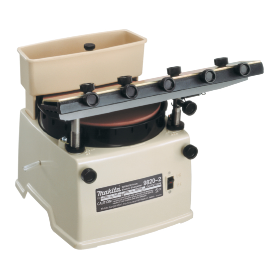
Makita 9820-2 Instruction Manual
200 mm (7-7/8") sharpener
Hide thumbs
Also See for 9820-2:
- Brochure (1 page) ,
- Instruction manual (8 pages) ,
- Instruction manual (25 pages)

Related Manuals for Makita 9820-2


Summary of Contents for Makita 9820-2
- Page 1 Sharpener 200 mm (7-718") MODEL 9820-2 INSTRUCTION MANUAL SPECIFICATIONS Wheel size No load speed Overall length Net weight x 25 mm x 75 5-3/8") Ibs) R/min. kg (24.3 (7-7/8" x 1" 3")
- Page 2 BEFORE CONNECTING YOUR TOOL TO A POWER SOURCE Be sure have read all GENERAL POWER TOOL SAFETY RULES GENERAL SAFETY PRECAUTIONS (For All Tools) KNOW YOUR POWER TOOL. Read the owner's manual carefully. Learn the tools applications and limitations, as well as the specific potential hazards peculiar t o KEEP GUARDS IN PLACE and in working order.
- Page 3 17. USE RECOMMENDED ACCESSORIES. Consult the owner's manual for recommended accessories. The use of improper accessories may cause risk of injury t o persons. 18. NEVER STAND ON TOOL. Serious injury could occur if the tool is tipped or if the cutting tool is accidentally contacted. 19.
- Page 4 GROUNDING INSTRUCTIONS ALL GROUNDED, CORD-CONNECTED TOOLS: In the event of a malfunction or breakdown, grounding provides a path of least resistance for electric current t o reduce the risk of electric shock. This tool is equipped with an electric cord hav- an equipment-grounding conductor and a grounding plug.
- Page 5 ADDITIONAL SAFETY RULES "No Use only wheels having a maximum operating speed at least as high as Load RPM" marked on the tool's nameplate. 2. Check the wheel carefully for cracks or damage before operation. Replace cracked or damaged wheel immediately. Secure the wheel carefully.
- Page 6 HOW TO USE Replacing grinding wheel Use the wrench provided to release the grinding wheel by turning the installation screw counterclockwise. To install the grinding wheel, follow the removal procedure in reverse. Adjusting wheel guard The top of the wheel guard should be 1 mm (approx.
- Page 7 Loosen the pole fastening screws and lift off the sharpening platform guide. To install the sharpening platform guide, follow the removal procedure in reverse. Adjusting sharpening platform guide using the sharpening platform guide to Sharpening platform guide (Rail) sharpen blade/knife, adjust the angle ad- justment screw to the desired blade/knife sharpening angle.
- Page 8 The nut for raising or lowering the pole on either side raises the pole 0.5 mm (1/32") for each graduation, when turned clock- wise, and lowers the pole, conversely, 0.5 mm (1/32") when turned counterclock- wise. Tilt the sharpening platform guide slightly with right side downward that the blade contacts the right side surface of the grind-...
- Page 9 Screw in clockwise the forward adjust screw on the right until the right upper edge of the blade comes into contact with the grinding wheel. Then fully tighten the fastening screw on the far right. Slide the holder to the right across sharpening platform guide.
- Page 10 Adjusting coolant flow Put water in the coolant reservoir. Turn the knob that the marking posi- tioned vertically to make the coolant flow. Turn the marking to the horizontal posi- tion to stop the coolant flow. NOTE : Adjust the coolant flow adequately. If the debris from the grinding wheel and the blade is washed away by the coolant, the coolant flow is excessive.
- Page 11 Switch action start the tool, press the ON side of the switch located on the front of the tool. turn the tool off, press the OFF side of the switch. Sharpening blade/knife After you have established the correct coolant flow, you can begin sharpening. Sharpen with the cutting edge away from you, holding the sharpening holder with both hands.
- Page 12 Sharpening power planer blades Sharpen your planer blades to a 40" angle. Power planer blade CAUTION : *Clean and dry the tool after operation. Be sure that the tool is switched off, unplugged and drained before attempting to move the tool.
- Page 13 ACCESSOR I ES CAUTION : These accessories or attachments are recommended for use with your Makita tool specified i n this manual. The use of any other accessories or attachments might present a risk of injury to persons. The accessories or attachments should be used only in the proper and intended manner.
- Page 14 Aug.-02-84 200 mm (7-7/8") SHARPENER Model 9820-2 Note: The switch and other part configurations may differ from country to country.
- Page 15 9820.2 MODEL Sep-19-'84 , " : , DESCRIPTION DESCRIPTION MACHINE MACHINE neilcai G~~~ 12 Knob 6 5 MOW, Vinyl Tube CORD ASSEMBLY Wheel Cover IASSembled Cord Plug & Item 20) Pan Head Screw M5x20 (With Washer) Flat Washer 10 set Plate Boll M10x30 lW8th Washer) Screw M6x31 Under...
- Page 16 MAKITA LIMITED ONE YEAR WARRANTY Warranty Policy Every Makita tool is thoroughly inspected and tested before leaving the factory. It is warranted to be free of defects from workmanship and materials for the period of ONE YEAR from the date of original purchase.