Table of Contents
Advertisement
Advertisement
Table of Contents

Related Manuals for Asus P4S533-MX


Summary of Contents for Asus P4S533-MX
- Page 1 P4S533-MX User Guide...
- Page 2 Product warranty or service will not be extended if: (1) the product is repaired, modified or altered, unless such repair, modification of alteration is authorized in writing by ASUS; or (2) the serial number of the product is defaced or missing.
-
Page 3: Table Of Contents
1.12 Connectors ... 1-16 Chapter 2: BIOS information 2.1 Managing and updating your BIOS ... 2-2 2.1.1 Using ASUS EZ Flash to update the BIOS ... 2-2 2.1.2 Using AFLASH to update the BIOS ... 2-4 2.1.3 CrashFree BIOS feature ... 2-7 2.2 BIOS Setup program ... - Page 4 Chapter 3: Software support 3.1 Install an operating system ... 3-2 3.2 Support CD information ... 3-2 3.2.1 Running the support CD ... 3-2 3.2.2 Drivers menu ... 3-3 3.2.3 Utilities menu ... 3-3 3.2.4 ASUS Contact Information ... 3-4...
-
Page 5: Notices
Notices Federal Communications Commission Statement This device complies with FCC Rules Part 15. Operation is subject to the following two conditions: • This device may not cause harmful interference, and • This device must accept any interference received including interference that may cause undesired operation. -
Page 6: Safety Information
Safety information Electrical safety • To prevent electrical shock hazard, disconnect the power cable from the electrical outlet before relocating the system. • When adding or removing devices to or from the system, ensure that the power cables for the devices are unplugged before the signal cables are connected. -
Page 7: About This Guide
1. ASUS Websites The ASUS websites worldwide provide updated information on ASUS hardware and software products. The ASUS websites are listed in the ASUS Contact Information on page viii. 2. Optional Documentation Your product package may include optional documentation, such as warranty flyers, that may have been added by your dealer. -
Page 8: Asus Contact Information
ASUS COMPUTER INTERNATIONAL (America) Address: General Fax: General Email: Technical Support Support Fax: General Support: Web Site: Support Email: ASUS COMPUTER GmbH (Germany and Austria) Address: General Fax: General Email: Technical Support Support Hotline: Support Fax: Support (Email): Web Site:... -
Page 9: P4S533-Mx Specifications Summary
P4S533-MX specifications summary Socket 478 for Intel On-die 512KB/256KB L2 cache with full speed Supports Intel R2.00 or later versions) Chipset Front Side Bus (FSB) 533/400 MHz Memory 2 x 184-pin DIMM sockets support for PC2700/2100/PC1600 non-ECC DDR DIMMs for up to 2GB memory... - Page 10 Accessories * Specifications are subject to change without notice. 2Mb Flash ROM, Award BIOS, TCAV, PnP, DMI2.0, WfM2.0, SM BIOS2.3, CrashFree BIOS, ASUS EZ Flash PCI 2.2, USB 2.0 WfM 2.0. DMI 2.0, WOL/WOR by PME Micro-ATX form factor: 9.6 in x 9.6 in (24.5 cm x 24.5 cm)
-
Page 11: Chapter 1: Product Introduction
Chapter 1 This chapter describes the features of the P4S533-MX motherboard. It includes brief descriptions of the motherboard components, and illustrations of the layout, jumper settings, and connectors. Product introduction... -
Page 12: Welcome
Welcome! Thank you for buying the ASUS The ASUS P4S533-MX motherboard delivers a host of new features and latest technologies making it another standout in the long line of ASUS quality motherboards! The motherboard incorporates the Intel ® coupled with the SiS 651 chipset to set a new benchmark for a cost-effective desktop platform solution. -
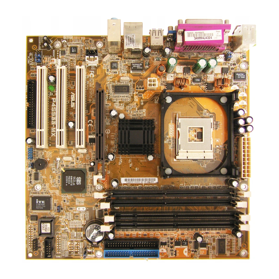
Page 13: Motherboard Components
Motherboard components Before you install the motherboard, learn about its major components and available features to facilitate the installation and future upgrades. Refer to the succeeding pages for the component descriptions. ASUS P4S533-MX motherboard user guide... - Page 14 ATX 12V connector. This power connector connects the 4-pin 12V plug from the ATX 12V power supply. North bridge controller. This SiS651 controller integrates a high performance host interface for the Intel Pentium 4 processor, a memory controller and SiS MuTIOL technology. CPU socket.
- Page 15 VGA port. This 15-pin VGA port connects to a VGA monitor. S/PDIF port. This port is for S/PDIF digital audio output devices. PS/2 keyboard port. This purple connector is for a PS/2 keyboard. ASUS P4S533-MX motherboard user guide 4-Speaker 6-Speaker...
-
Page 16: Special Features
4.2GB/s data transfer rates. SDRAM and DDRAM Combo (page 1-12) P4S533-MX has two DDR sockets and two SDR sockets that support up to 2GB non-ECC PC2700/2100/PC1600 or PC133/PC100 SDRAM DIMMs. ASUS EZ Flash (page 2-2) With ASUS EZ Flash, you can update BIOS before entering operating system. -
Page 17: Motherboard Layout
Accelerated Graphics Port AUX1 PCI Slot 1 Audio ® MDC1 Codec PCI Slot 2 CHA_FAN1 P4S533-MX SB_PWR1 PCI Slot 3 FP_AUDIO1 ASUS P4S533-MX motherboard user guide 24.4cm (9.6in) ATX Power Connector SiS651 HOST/ Memory Controller (AGP) SiS962L MuTLOL Media USBPWR_56 USB_56... -
Page 18: Before You Proceed
® P4S533-MX P4S533-MX Onboard LED Install only 1.5V AGP cards on this motherboard! SB_PWR1 Standby Powered... -
Page 19: Motherboard Installation
Place eight (8) screws into the holes indicated by circles to secure the motherboard to the chassis. Do not overtighten the screws! Doing so may damage the motherboard. Place this side towards the rear of the chassis ASUS P4S533-MX motherboard user guide... -
Page 20: Central Processing Unit (Cpu)
Central Processing Unit (CPU) 1.8.1 Overview The motherboard comes with a surface mount 478-pin Zero Insertion Force (ZIF) socket. The socket is designed for the Intel package with 512/256KB L2 cache on 0.13 micron process. This processor supports 533/400MHz front side bus (FSB), and allows data transfer rates of 4.2GB/s and 3.2GB/s. -
Page 21: Installing The Cpu
6. Install a CPU heatsink and fan following the instructions that came with the heatsink package. 7. Connect the CPU fan cable to the CPU_FAN1 connector on the motherboard. ASUS P4S533-MX motherboard user guide Socket Lever 90 - 100 Gold Mark 1-11... -
Page 22: System Memory
P4S533-MX 168-Pin DIMM Sockets ® P4S533-MX P4S533-MX 184-Pin DDR DIMM Sockets 1. Make sure to unplug the power supply before adding or removing DIMMs or other system components. Failure to do so may cause severe damage to the motherboard and other system components. -
Page 23: Expansion Slots
When using PCI cards on shared slots, ensure that the drivers support “Share IRQ” or that the cards do not need IRQ assignments. Otherwise, conflicts will arise between the two PCI groups, making the system unstable and the card inoperable. ASUS P4S533-MX motherboard user guide Standard Function System Timer Keyboard Controller... -
Page 24: Jumpers
+5VSB lead when these jumpers are set to +5VSB. Otherwise, the system would not power up. 2. The total current consumed must NOT exceed the power supply capability (+5VSB) whether under normal condition or in sleep mode. ® P4S533-MX P4S533-MX USB Device Wake Up 1-14 USBPWR_34 USBPWR_12 +5VSB (Default) -
Page 25: Clear Rtc Ram (Clrtc1)
Removing the cap will cause system boot failure! ® P4S533-MX P4S533-MX Clear RTC RAM Setting You do not need to clear the RTC when the system hangs due to overclocking. For system failure due to overclocking, use the C.P.R. (CPU Parameter Recall) feature. -
Page 26: Connectors
(Pin 5 is removed to prevent incorrect insertion when using ribbon cables with pin 5 plug). ® P4S533-MX P4S533-MX Floppy Disk Drive Connector 2. IDE connectors (40-1 pin PRI_IDE1, SEC_IDE1) This connector supports the provided UltraDMA133/100/66 IDE hard disk ribbon cable. Connect the cable’s blue connector to the primary (recommended) or... - Page 27 230W, or 300W for a fully configured system. The system may become unstable and may experience difficulty powering up if the power supply is inadequate. ® P4S533-MX P4S533-MX ATX Power Connectors ASUS P4S533-MX motherboard user guide COM1 PIN 1 ATXPWR1 ATX12V1 +12V DC...
- Page 28 DO NOT place jumper caps on the fan connectors! ® P4S533-MX P4S533-MX 12-Volt Cooling Fan Power 6. GAME/MIDI connector (16-1 pin GAME1) This connector supports a GAME/MIDI module. Connect an optional GAME/MIDI cable to this connector. The GAME/MIDI port on the module connects a joystick or a game pad for playing games, and MIDI devices for playing or editing audio files.
- Page 29 8. Front panel audio connector (10-1 pin FP_AUDIO1) This is an interface for the Intel front panel audio cable that allow convenient connection and control of audio devices. ® P4S533-MX P4S533-MX Front Panel Audio Connector ASUS P4S533-MX motherboard user guide USB56 (Blue) FP_AUDIO1...
- Page 30 CD-ROM, TV tuner, or MPEG card. ® P4S533-MX P4S533-MX Internal Audio Connectors 10. MDC header (10-1pin MDC) This ASUS proprietary modem header accomodates an optional modem module. (since PCB R1.03 or later versions) ® P4S533-MX P4S533-MX MDC Header...
-
Page 31: System Panel Connector
This connector supplies power to the hard disk activity LED. The read or write activities of any device connected to the primary or secondary IDE connector cause this LED to light up. ASUS P4S533-MX motherboard user guide Speaker Connector Power LED... - Page 32 1-22 Chapter 1: Product introduction...
-
Page 33: Chapter 2: Bios Information
Chapter 2 This chapter tells how to change system settings through the BIOS Setup menus. Detailed descriptions of the BIOS parameters are also provided. BIOS information... -
Page 34: Managing And Updating Your Bios
BIOS later. 2.1.1 Using ASUS EZ Flash to update the BIOS The ASUS EZ Flash feature allows you to easily update the BIOS without having to go through the long process of booting from a diskette and using a DOS-based utility. - Page 35 5. At the prompt, “Please Enter File Name for NEW BIOS: _”, type in the BIOS file name that you downloaded from the ASUS website, then press <Enter>. EZ Flash will automatically access drive A to look for the file name that you typed.
-
Page 36: Using Aflash To Update The Bios
2.1.2 Using AFLASH to update the BIOS Creating a bootable disk AFLASH.EXE is a Flash Memory Writer utility that updates the BIOS by uploading a new BIOS file to the programmable flash ROM on the motherboard. This file works only in DOS mode. To determine the BIOS version of your motherboard, check the last four numbers of the code displayed on the upper left-hand corner of your screen during bootup. -
Page 37: Updating The Bios
BIOS revision will solve your problems. Careless updating may result to more problems with the motherboard! 1. Download an updated ASUS BIOS file from the Internet (WWW or FTP) (see ASUS CONTACT INFORMATION on page viii for details) and save to the boot floppy disk you created earlier. - Page 38 BIOS file you saved to the boot disk. If the Flash Memory Writer utility is not able to successfully update a complete BIOS file, the system may not boot. If this happens, call the ASUS service center for support.
-
Page 39: Crashfree Bios Feature
To use the CrashFree BIOS feature on this motherboard, install a VGA card into one of the expansion slots before rebooting the computer. On motherboards with onboard VGA, such as the P4S533-MX, you will not see the screen display when the BIOS crashes even if you reboot the computer. -
Page 40: Bios Setup Program
BIOS Setup program This motherboard supports a programmable Flash ROM that you can update using the provided utility described in section “2.1 Managing and updating your BIOS.” Use the BIOS Setup program when you are installing a motherboard, reconfiguring your system, or prompted to “Run Setup”. This section explains how to configure your system using this utility. -
Page 41: Legend Bar
<PgDn> or the up and down arrow keys to scroll through the entire help document. Press <Home> to display the first page, press <End> to go to the last page. To exit the help window, press <Enter> or <Esc>. ASUS P4S533-MX motherboard user guide Function Description Displays the General Help screen from anywhere... -
Page 42: Main Menu
Sub-menu Note that a right pointer symbol (as shown on the left) appears to the left of certain fields. This pointer indicates that you can display a sub-menu from this field. A sub- menu contains additional options for a field parameter. To display a sub-menu, move the highlight to the field and press <Enter>. - Page 43 Configuration options: [All Errors] [No Error] [All but Keyboard] [All but Disk] [All but Disk/Keyboard] Installed Memory [XXX MB] This field automatically displays the amount of conventional memory detected by the system during the boot process. ASUS P4S533-MX motherboard user guide 2-11...
-
Page 44: Primary And Secondary Master/Slave
2.3.1 Primary and Secondary Master/Slave Type [Auto] Select [Auto] to automatically detect an IDE hard disk drive. If automatic detection is successful, Setup automatically fills in the correct values for the remaining fields on this sub-menu. If automatic detection fails, this may be because the hard disk drive is too old or too new. - Page 45 Type field to [User Type HDD] and the Translation Method field to [Manual]. CHS Capacity This field shows the drive’s maximum CHS capacity as calculated by the BIOS based on the drive information you entered. ASUS P4S533-MX motherboard user guide 2-13...
-
Page 46: Keyboard Features
Maximum LBA Capacity This field shows the drive’s maximum LBA capacity as calculated by the BIOS based on the drive information you entered. Multi-Sector Transfers [Maximum] This option automatically sets the number of sectors per block to the highest number that the drive supports. Note that when this field is automatically configured, the set value may not always be the fastest value for the drive. -
Page 47: Advanced Menu
This feature tells the clock generator what frequency to send to the system bus and PCI bus. The bus frequency (external frequency) multiplied by the bus multiple equals the CPU speed. ASUS P4S533-MX motherboard user guide (when CPU Speed is set to [Manual]) (when CPU Speed is set to [Manual]) - Page 48 Memory Frequency [Auto] This field determines whether the memory clock frequency is set to be in synchronous or asynchronous mode with respect to the system frequency. The options that appear in the popup menu vary according to the CPU Frequency (MHz).
-
Page 49: Chip Configuration
This item controls the number of DDR SDRAM clocks used for DDR SDRAM parameters. Configuration options: [6T] [7T] [5T] [4T] SDRAM Command Lead-off Time [Auto] Configuration options: [Auto] [2T] [1T] ASUS P4S533-MX motherboard user guide (value depends on SDRAM SPD) (value depends on SDRAM SPD) (value depends on SDRAM SPD) - Page 50 Graphics Aperture Size [64MB] This feature allows you to select the size of mapped memory for AGP graphic data. Configuration options: [4MB] [8MB] [16MB] [32MB] [64MB] [128MB] [256MB] AGP Capability [4X Mode] This motherboard supports the AGP 4X interface that transfers video data at 1066MB/s.
-
Page 51: I/O Device Configuration
This field sets the I/O address for the game port. Configuration options: [Disabled] [200H-207H] [208H-20FH] Onboard MIDI I/O [Disabled] This field sets the I/O address for the MIDI I/O port. Configuration options: [Disabled] [330H-331H] [300H-301H] ASUS P4S533-MX motherboard user guide 2-19... -
Page 52: Pci Configuration
2.4.3 PCI Configuration Slot 1, Slot 2, Slot 3 IRQ [Auto] These fields automatically assign the IRQ for each PCI slot. The default setting for each field is [Auto], which utilizes auto-routing to determine IRQ assignments. Configuration options: [Auto] [NA] [3] [4] [5] [7] [9] [10] [11] [12] [14] [15] PCI/VGA Palette Snoop [Disabled] Some non-standard VGA cards, like graphics accelerators or MPEG video cards, may not show colors properly. - Page 53 [Auto] for optimum performance. Configuration options: [Disabled] [Auto] Onboard AC97 Modem Controller [Auto] This field allows you to disable the onboard AC97 modem controller or set to the default [Auto] for optimum performance. Configuration options: [Disabled] [Auto] ASUS P4S533-MX motherboard user guide 2-21...
-
Page 54: Power Menu
2.4.3.2 PCI IRQ Resource Exclusion IRQ XX Reserved [No/ICU] These fields indicate whether or not the displayed IRQ for each field is being used by a legacy (non-PnP) ISA card. The setting [No/ICU] for an IRQ field indicates that you are using the ISA Configuration Utility (ICU), and that this particular IRQ is NOT required by a legacy ISA card. - Page 55 This field allows you to enable or disable the ACPI Suspend-to-RAM feature. To support this feature, the +5VSB of the power supply should have the capacity to provide more than 720mA current. Configuration options: [Disabled] [Enabled] ASUS P4S533-MX motherboard user guide 2-23...
-
Page 56: Power Up Control
2.5.1 Power Up Control AC PWR Loss Restart [Disabled] This allows you to set whether or not to reboot the system after power interruptions. [Disabled] leaves your system off while [Enabled] reboots the system. [Previous State] sets the system back to the state it was before the power interruption. -
Page 57: Hardware Monitor
If any of the monitored items is out of range, the following error message appears: “Hardware Monitor found an error. Enter Power setup menu for details”. You will then be prompted to “Press F1 to continue or DEL to enter SETUP”. ASUS P4S533-MX motherboard user guide 2-25... -
Page 58: Boot Menu
Boot Menu Boot Sequence The Boot menu allows you to select among the four possible types of boot devices listed using the up and down arrow keys. By using the <+> or <Space> key, you can promote devices and by using the <-> key, you can demote devices. Promotion or demotion of devices alters the priority which the system uses to search for a boot device on system power up. - Page 59 This item allows you to enable or disable the processor Hyper-Threading Technology. Configuration options: [Disabled] [Enabled] The item Hyper-Threading Technology appears only if you installed an Intel Pentium 4 CPU that supports this feature. ASUS P4S533-MX motherboard user guide 2-27...
-
Page 60: Exit Menu
Exit Menu When you have made all of your selections from the various menus in the Setup program, save your changes and exit Setup. Select Exit from the menu bar to display the following menu. Pressing <Esc> does not immediately exit this menu. Select one of the options from this menu or <F10>... -
Page 61: Chapter 3: Software Support
Chapter 3 This chapter describes the contents of the support CD that comes with the motherboard package. Software support... -
Page 62: Install An Operating System
The support CD that came with the motherboard contains useful software and several utility drivers that enhance the motherboard features. The contents of the support CD are subject to change at any time without notice. Visit the ASUS website for updates. 3.2.1 Running the support CD To begin using the support CD, simply insert the CD into your CD-ROM drive. -
Page 63: Software And Drivers Description
ASUS PC Probe V2.18.08 This smart utility monitors the fan speed, CPU temperature, and system voltages, and alerts you on any detected problems. This utility helps you keep your computer at a healthy operating condition. ASUS P4S533-MX motherboard user guide Right Left Arrow... - Page 64 ASUS Update V3.41.01 This item installs the ASUS Update. This program allows you to download the latest version of the BIOS from the ASUS website. Microsoft Direct X 8.1 Driver This item installs the Microsoft V8.1 driver. PC-CILLIN 2002 This item installs the PC-cillin 2002 anti-virus software. View the PC-CILLIN online help for detailed information.