Table of Contents
Advertisement
ELECTRIC
DRYER INSTALLATION
INSTRUCTIONS
Para una version de estas instrucciones
en espa_ol, visite www.Whirlpool.com
Table
of Contents
DRYER SAFETY .........................................................................
2
.............................................
3
Tools and Parts ......................................................................
3
....................................................
4
................................................
4
INSTALL LEVELING LEGS .........................................................
6
ELECTRICAL INSTALLATION ...................................................
7
Power Supply Cord Connection ...........................................
8
Direct Wire Connection .......................................................
10
VENTING ...................................................................................
13
.........................................................
13
Plan Vent System .................................................................
14
Venting Kits ..........................................................................
14
Install Vent System ..............................................................
15
iNLET HOSE ..........................................................
16
CONNECT VENT ......................................................................
17
LEVEL DRYER ..........................................................................
17
INSTALLATION CHECKLIST ..............................
18
DOOR REVERSAL (OPTIONAL} ..............................................
19
iNSTALLATiON
NOTES
Date of purchase:
Date of installation:
Installer:
Model number:
Serial number:
W10057363B
W10310420B
=SP
Advertisement
Table of Contents

Related Manuals for Maytag MED7000XG0


Summary of Contents for Maytag MED7000XG0
-
Page 1: Table Of Contents
ELECTRIC DRYER INSTALLATION INSTRUCTIONS Para una version de estas instrucciones en espa_ol, visite www.Whirlpool.com Table of Contents DRYER SAFETY ................. INSTALLATION REQUIREMENTS ..........Tools and Parts ..............LOCATION REQUIREMENTS ............ ELECTRICAL REQUIREMENTS ..........INSTALL LEVELING LEGS ............ELECTRICAL INSTALLATION ........... Power Supply Cord Connection ........... -
Page 2: Dryer Safety
DRYER S_ETY Your safety and the safety of others are very important. We have provided many important safety messages in this manual and on your appliance. Always read and obey all safety messages. This is the safety alert symbol. This symbol alerts you to potential hazards that can kill or hurt you and others. All safety messages will follow the safety alert symbol and either the word "DANGER"... -
Page 3: Installation Requirements
LATION REQUIREMENTS TOOLS PARTS Gather the required tools and parts before starting installation. Tools needed: Parts needed: (Not supplied with dryer) [] Vent clamps [] Vent elbows and ductwork Additional parts may be required, depending in your installation. Check local codes. Check existing electrical supply and venting. Read "Electrical Requirements"... -
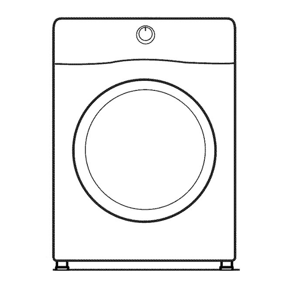
Page 4: Location Requirements
DRYER DIMENSIONS LOCATXON REQUXREMENT$ Check code requirements. Some codes limit, or do not permit, Front view: installing dryer in garages, closets, mobile homes, or sleeping ram) (686 quarters. Contact your local building inspector. © 381/8" (968 ram) Explosion Hazard Keep flammable materials and vapors, such as gasoline, away from dryer. - Page 5 installation spacing for recessed area ELECTR[C, REQU[REMENWS or closet installation All dimensions show recommended and minimum spacing it is your responsibility: allowed. [] To contact a qualified electrical installer. [] Additional spacing should be considered for ease of installation [] To be sure that the electrical connection is adequate and in and servicing.
-
Page 6: Install Leveling Legs
if your outlet looks like this: INS%ALL LE¥ L[NG LEGS Then choose a 4-wire power supply cord with ring or spade terminals and UL listed strain relief. The 4-wire power supply cord, at least 4 ft. (1.22 m) long, must have four 10-gauge Excessive Weight Hazard copper wires and match a 4-wire receptacle of Use two or more people to move and install dryer. -
Page 7: Electrical Installation
ELECTRIC LATION For direct wire installations: For power supply cord installations: Fire Hazard Fire Hazard Use 10 gauge copper wire. Use a new UL listed 30 amp power supply cord. Use a UL listed strain relief. Use a UL listed strain relief. Disconnect power before making electrical connections. -
Page 8: Power Supply Cord Connection
Power Supply Cord Connection Power supply cord strain relief: 4=Wire Power Supply Cord Connection IMPORTANT: A 4-wire connection is required for mobile homes and where local codes do not 3ermit the use of 3-wire connections. 4-wire receptacle (NEMA 4-prong plug type 14-30R) Remove the screws from a 3/4"... - Page 9 . Remove center screw Connect ground wire Connect ground wire (F) (green or bare) of power supply cord Remove center terminal block screw (B). under green external ground conductor screw (A). Tighten screw. Connect neutral wire Connect neutral wire (white or center) (C) of power supply cord under center terminal block screw (B).
-
Page 10: Direct Wire Connection
Direct Wire Connection Direct wire strain relief 4=Wire Direct Wire Connection IMPORTANT: A 4-wire connection is required for mobile homes and where local codes do not permit 3-wire connections. Prepare your 4=wire cable direct connection Unscrew the removable conduit connector (A) and any Direct wire cable must have 5 ft. - Page 11 3=Wire Direct Wire Connection Connect neutral ground wire and neutral wire Use where local codes permit connecting cabinet-ground conductor to neutral wire. Prepare your 3=wire cable direct connection Connect neutral ground wire (E) and place hooked end (hook facing right) of neutral wire (white or center wire) (C) of direct wire Direct wire cable must have 5 ft.
- Page 12 Connect remaining wires neutral wire Place hooked ends of remaining direct wire cable wires under outer terminal block screws (hooks facing right). Squeeze hooked ends together and tighten screws. Finally, reinsert tab of terminal Connect neutral ground wire (E) and neutral wire (white or block cover into slot of dryer rear panel.
-
Page 13: Venting
Exhaust hoods: [] An exhaust hood should cap the vent to keep rodents and Venting Requirements insects from entering the home. [] Must be at least 12" (305 mm) from ground or any object that may obstruct exhaust (such as flowers, rocks, bushes, or snow). -
Page 14: Plan Vent System
Determine vent path: Plan Vent System [] Select route that will provide straightest and most direct path outdoors. Choose your exhaust installation type [] Plan installation to use fewest number of elbows and turns. Recommended exhaust installation: [] When using elbows or making turns, allow as much room --------C as possible. -
Page 15: Install Vent System
CONNECT INLET HOSE Install Vent System The dryer must be connected to the cold water faucet using the new inlet hoses. Do not use old hoses. install exhaust hood NOTE: Replace inlet hoses after 5 years of use to reduce the risk of hose failure. -
Page 16: Connect Inlet Hose
and tighten coupling Using pliers, tighten the couplings with additional two-thirds turn. NOTE: Do not overtighten. Damage to the coupling can result. Remove protective cap from 4,. Attach long hose to "Y" water inlet valve. Attach other end connector and tighten couplings of long hose to fill valve at bottom of dryer back panel. -
Page 17: Connect Vent
CONNECT LE_L Connect vent to exhaust outlet Level dryer Place level here © Using a 4" (102 mm) clamp, connect vent to exhaust outlet Check levelness of dryer from in dryer. If connecting to existing vent, make sure vent is side to side. -
Page 18: Complete Installation Checklist
COMPLETE INSTAL [_ Check that all parts are now installed. If there is an extra [_ If you live in a hard water area, use of a water softener is part, go back through steps to see what was skipped. recommended to control the buildup of scale through the water system in the dryer. -
Page 19: Door Reversal
Move the door strike DOOR RE TRS (OPTION ) The following instructions are for models with a round-shaped door. ® ® IMPORTANT: For models with a square shaped door, an ® ® additional kit is needed. Please contact your retailer, or see the For Assistance or Service page in your Use and Care Guide. - Page 20 Reverse outer window assembly Remove outer window assembly from trim ring Handle Using a Phillips screwdriver, remove the 2 screws from the outer window retainer and rotate the outer window assembly clockwise until the square notches line up with the 4 tabs on the trim ring indicated with arrows in the figure A above.
- Page 21 Rotate and reassemble outer window assembly to trim ring Bottom of door Notches Using a Torx ®T25 screwdriver, remove the 3 Torx screws securing the latch plate and latch backing plate and the 5 screws holding the hinge assembly in place. Reinstall hinge and latch opposite...
- Page 22 Reinstall inner door assembly Bottom of door Position the door with the inside of the door facing up. Reinstall the 10 screws securing the inner door to the outer door. Using a Torx ® T25 screwdriver, remove the 4 screws on the dryer.
- Page 24 W10057363B W10310420B © 2010 11/10 Printed in U.S.A. All rights reserved...