Advertisement
Quick Links
Congratualtions on choosing an Ariston appliance, which you will find is dependable and easy to use. We recommend
that you read this manual for best performance and to extend the life of your appliance. Thank you.
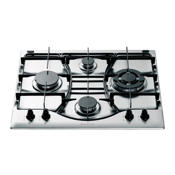
A. Gas Burners
B. Support Grid for Cookware
C. Control Knobs for Gas Burners
D. Ignitor for Gas Burners (only on certain models)
E. Ignition Button for Gas Burners (only on certain
models)
F. Safety Device (only on certain models) - Activates if
the flame accidentally goes out (spills, drafts, etc.),
interrupting the delivery of gas to the burner.
The position of the corresponding gas burner or electric
hot plate (if present) is indicated on each control knob.
Gas Burners
The burners differ in size and power. Choose the most
appropriate one for the diameter of the cookware being
used.
The burner can be regulated with the corresonding control
knob by using one of the following settings:
• Off
High
Low
To turn on one of the burners, place a lighted match or
lighter near the burner, press the knob all the way in and
turn in the counter-clockwise direction to the "High" setting.
On those models fitted with a safety device (F), the
knob must be pressed in for about 6 seconds until the
device that keeps the flame lighted warms up.
Close-up View
How To Use Your Appliance
2
On those models fitted with an ignitor (D), the "E"
ignition button, identified by the
pressed and then the corresponding knob pushed all the
way in and turned in the counter-clockwise direction to
the "High" setting.
Some models are equipped with an ignition switch
incorporated into the control knob. If this is the case, the
ignitor (D) is present, but not the "E" switch (the
is located near each knob).
To light a burner, simply press the corresponding knob all
the way in and then turn it in the counter-clockwise
direction to the "High" setting, keeping it pressed in until
the burner lights.
Caution: If the burner accidently goes out, turn off the
gas with the control knob and try to light it again after
waiting at least 1 minute.
To turn off a burner, turn the knob in the clockwise
direction until it stops (it should be on the "•" setting).
symbol, must first be
symbol
Advertisement

Related Manuals for Ariston CISPH 640 Series


Summary of Contents for Ariston CISPH 640 Series
- Page 1 Congratualtions on choosing an Ariston appliance, which you will find is dependable and easy to use. We recommend that you read this manual for best performance and to extend the life of your appliance. Thank you. Close-up View A. Gas Burners B.
-
Page 2: Practical Advice
How to Keep Your Cooktop in Shape Before cleaning or performing maintenance on your • Stainless steel can be stained if it remains in contact appliance, disconnect it from the electrical power supply. with highly calcareous water or aggressive detergents To extend the life of the cooktop, it is absolutely (containing phosphorous) for an extended period of indispensable that it be cleaned carefully and... -
Page 3: Is There A Problem
Is there a problem? It may occur that the cooktop does not function or does The burner does not remain on when set to "Low". not function properly. Before calling customer service for Check to make sure that: assistance, lets see what can be done. •... - Page 4 Always check to make sure that the control knobs are Check the condition of the appliance after it has been on the “•”/” ” setting when the appliance is not in use; unpacked; Cut the power supply cord after disconnecting it from Disconnect the appliance from the power supply in the the electrical mains when you decide to no longer use event of malfunction and always before cleaning or...
- Page 5 f) In the event the cooktop is not installed above a built- in oven, a wood panel must be inserted as insulation. This panel must be placed at least 20 mm from the HOOD bottom of the cooktop itself. Min. Important: When installing the cooktop above a built-in oven, the oven should be placed on two wooden strips;...
- Page 6 The appliance is fitted with an adjustable, "L" shaped Connect the Green & Yellow wire to the terminal marked connector and a gasket for the attachment to the gas supply. “E” or or coloured Green or Green & Yellow. Should this connector have to be turned, the gasket must be Connect the Brown wire to the terminal marked “L”...
-
Page 7: Burners And Nozzle Specifications
Burners and Nozzle Specifications Table 1 Liquid Gas Natural Gas Burner Diameter Thermal Power By-pass Nozzle Flow* Nozzle Flow* Nozzle Flow* (mm) kW (p.c.s.*) 1/100 1/100 1/100 1/100 (mm) Nom. Red. (mm) (mm) (mm) Fast 3.00 (Large) (R) Reduced Fast 2.60 0.70 (RR) - Page 12 HOOD Min. 555 mm...