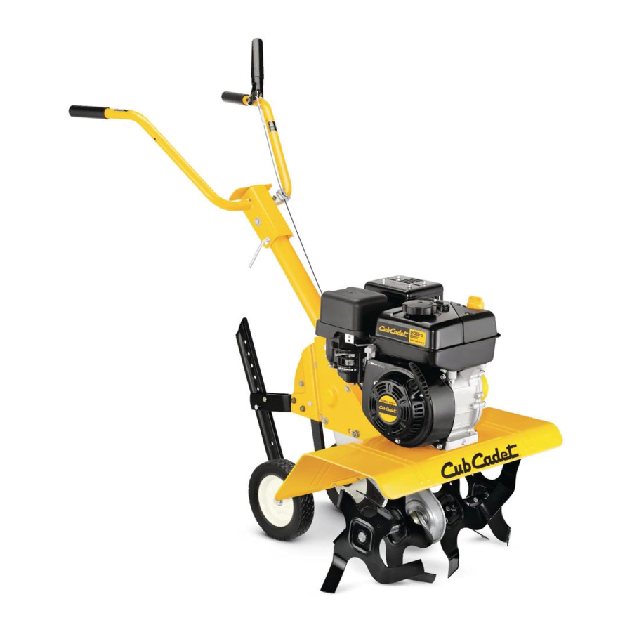
Cub Cadet RT 65 Operator's Manual
Rear tine tiller
Hide thumbs
Also See for RT 65:
- Parts manual (41 pages) ,
- Operator's manual (40 pages) ,
- Illustrated parts manual (24 pages)
Table of Contents
Advertisement
Available languages
Available languages
Safe Operation Practices • Set-Up • Operation • Maintenance • Service • Troubleshooting • Warranty
O
'
M
peratOr
s
anual
Rear Tine Tiller — Model RT 65
WARNING
READ AND FOLLOW ALL SAFETY RULES AND INSTRUCTIONS IN THIS MANUAL
BEFORE ATTEMPTING TO OPERATE THIS MACHINE.
FAILURE TO COMPLY WITH THESE INSTRUCTIONS MAY RESULT IN PERSONAL INJURY.
CUB CADET LLC, P.O. BOX 361131 CLEVELAND, OHIO 44136-0019
Printed In USA
Form No. 769-03598
(October 30, 2007)
Advertisement
Chapters
Table of Contents

Related Manuals for Cub Cadet RT 65


Summary of Contents for Cub Cadet RT 65
- Page 1 READ AND FOLLOW ALL SAFETY RULES AND INSTRUCTIONS IN THIS MANUAL BEFORE ATTEMPTING TO OPERATE THIS MACHINE. FAILURE TO COMPLY WITH THESE INSTRUCTIONS MAY RESULT IN PERSONAL INJURY. CUB CADET LLC, P.O. BOX 361131 CLEVELAND, OHIO 44136-0019 Printed In USA Form No. 769-03598...
-
Page 2: Table Of Contents
Choose from the options below: ◊ Visit us on the web at www.cubcadet.com ◊ Locate your nearest Cub Cadet Dealer at (877) 282-8684 ◊ Write us at Cub Cadet LLC • P.O. Box 361131 • Cleveland, OH • 44136-0019... -
Page 3: Important Safe Operation Practices
Important Safe Operation Practices WARNING! This symbol points out important safety instructions which, if not followed, could endanger the personal safety and/or property of yourself and others. Read and follow all instructions in this manual before attempting to operate this machine. Failure to comply with these instructions may result in personal injury. - Page 4 When practical, remove gas-powered equipment After striking a foreign object, stop the engine, disconnect from the truck or trailer and refuel it on the ground. the spark plug wire and ground against the engine. If this is not possible, then refuel such equipment on Thoroughly inspect the machine for any damage.
- Page 5 Average Useful Life If the fuel tank has to be drained, do this outdoors. Observe proper disposal laws and regulations for gas, oil, According to the Consumer Products Safety Commission etc. to protect the environment. (CPSC) and the U.S. Environmental Protection Agency (EPA), Notice Regarding Emissions this product has an Average Useful Life of seven (7) years, or 130 hours of operation.
-
Page 6: Assembly & Set-Up
Assembly & Set-Up Contents of Carton • One Tiller • One Handlebar Assembly • One Shift Rod • One Depth Stake • One Operator’s Manual • One Engine Operator’s Manual Assembly Depth Stake WARNING! Unpacking Instructions Disconnect the spark plug wire and ground it against the engine to prevent unintended NOTE: Reference to the right or left side of the tiller is starting. - Page 7 Handle Clutch Cable Remove the top two bolts and flange lock nuts from the Attach the clutch cable to the handle as follows: (be careful not handle mounting brackets, but do not remove the bottom to kink the cable) bolt and nut. See Fig. 3-2. Remove the threaded eyebolt and nut from the cable end.
- Page 8 Fasten the threaded eyebolt onto the bail by securing it Insert the longer end of the control rod through the hole in from the top with the slot head screw, flat washers and lock the gear selector handle and secure with the hairpin clip. nut.
- Page 9 Set-Up Tires The tires on the tiller may be over-inflated for shipping purposes. Reduce the tire pressure before operating the tiller. Recommended operating tire pressure is approximately 20 PSI (check the sidewall of the tire for the manufacturer’s recommended pressure). Be sure that both tires are inflated equally or the tiller will pull to one side.
-
Page 10: Controls & Features
Controls and Features Clutch Control Gear Selection Handle Handle Adjustment Lock Depth Stake Figure 4-1 Throttle Control Engine Controls The throttle control lever is located on the engine. It controls the See the separate Engine Operator’s Manual for additional information and functions of the engine controls. engine speed and stops the engine. -
Page 11: Operation
Operation Starting the Engine Setting The Depth Tilling depth is controlled by the depth stake which can be WARNING! Read, understand, and follow all adjusted to five different settings. Adjust the side shields as you instructions and warnings on the machine and in adjust the depth stake. -
Page 12: Operating The Tiller
NOTE: Use the reverse tine drive when tilling virgin When breaking up sod and for shallow cultivation, use the setting which gives 1” of tilling depth (second hole from ground, sod, or hard soil. Use the forward tine drive when the top). -
Page 13: Maintenance & Adjustments
Maintenance & Adjustments Wheel Shafts WARNING! Disconnect the spark plug wire and ground it against the engine before performing any Remove wheel assemblies and lubricate the axle shafts at least maintenance or repairs. once a season. Maintenance Adjustments Engine Belt Tension Refer to the separate Engine Operator’s Manual for engine WARNING! Never attempt to make any... - Page 14 Off-Season Storage If the tiller will not be used for a period longer than 30 days, the following steps should be taken to prepare the tiller for storage. • Clean the exterior of the engine and the entire tiller thoroughly. Lubricate the tiller as described in the lubrication instructions.
-
Page 15: Service
Service Belt Replacement Remove the belt keeper bracket located behind the engine pulley by removing the two hex bolts and lock washers. Your tiller has been engineered with a belt made of special See Fig. 7-2. material (Kevlar Tensile) for longer life and better performance. It should not be replaced with an off-the-shelf belt. -
Page 16: Troubleshooting
Troubleshooting Problem Cause Remedy Engine fails to start Fuel tank empty, or stale fuel. Fill tank with clean, fresh gasoline. Throttle control lever not in correct starting Move throttle lever to start position. position (if equipped). Blocked fuel line. Clean fuel line. Dirty air cleaner. -
Page 17: Replacement Parts
Replacement Parts Component Part Number and Description 754-0434, Drive Belt, 4LX58.16 LG 742-0305, Articulating Tine 746-1117, Drive Cable 734-0808, Tires 17211-ZL8-023, Air Filter 98079-56846, Spark Plug Phone (800) 800-7310 to order replacement parts or a complete Parts Manual (have your full model number and serial number ready). Parts Manual downloads are also available free of charge at www.mtdproducts.com. - Page 18 Notes...
- Page 19 11 — n ectiOn Otes...
- Page 20 MANUFACTURER’S LIMITED WARRANTY FOR EDGERS, STRING TRIMMERS & TILLERS The limited warranty set forth below is given by Cub Cadet LLC with c. Cub Cadet does not extend any warranty for products sold or respect to new merchandise purchased and used in the United States,...
- Page 21 Medidas importantes de seguridad • Configuración • Funcionamiento • Mantenimiento • Servicio • Solución de problemas • Garantía anual del OperadOr Cultivadora de Dientes Traseros — Modelo RT 65 ADVERTENCIA LEA Y SIGA TODAS LAS INSTRUCCIONES DE ESTE MANUAL ANTES DE PONER EN FUNCIONAMIENTO ESTA MÁQUINA.
- Page 22 Elija entre las opciones que se presentan a continuación: ◊ Visite nuestro sitio web en www.cubcadet.com ◊ Llame a un representante de Asistencia al Cliente al (800) 965-4CUB ◊ Escríbanos a Cub Cadet LLC • P.O. Box 361131 • Cleveland, OH • 44136-0019...
-
Page 23: Importante Medidas Importantes De Seguridad
Medidas importantes de seguridad ¡ADVERTENCIA! La presencia de este símbolo indica que se trata de instrucciones importantes de seguridad que se deben respetar para evitar poner en peligro su seguridad personal y/o material y la de otras personas. Lea y siga todas las instrucciones de este manual antes de poner en funcionamiento esta máquina. - Page 24 Cuando sea factible, retire el equipo a gasolina del Después de golpear con algún objeto extraño, detenga el camión o remolque y llénelo en el suelo. Si esto motor, desconecte el cable de la bujía y conecte el motor a no es posible, llene el equipo en un remolque con masa.
- Page 25 Vida útil media Si debe vaciar el tanque de combustible, hágalo al aire libre. Respete las normas referentes a la disposición correcta de Según la Comisión de Seguridad de Productos para el residuos y las reglamentaciones sobre gasolina, aceite, etc. Consumidor de los Estados Unidos (CPSC) y la Agencia de para proteger el medio ambiente.
-
Page 26: Ensamblado Y Configuración
Montaje y Configuración El Contenido del Cartón • Un Cultivadora • Un Unidad de la Manija • Un Varilla de control • Un Depth Stake • Un Manual de Operario • Un Manual de Operario de Motor Montaje Estaca de profundidad ¡ADVERTENCIA! Desembalar Instrucciones Desconecte el cable de la bujía y... - Page 27 Manija Cable del Embrague Retire los dos pernos superiores y las tuercas de seguridad Fije el cable del embrague a la manija de la siguiente manera: con reborde de los soportes de montaje de la manija, pero (tenga cuidado de no torcer el cable)) no retire el perno y la tuerca inferiores.
- Page 28 Fije el perno de ojo roscado al gancho sujetándolo desde Inserte el extremo más largo de la varilla de control en el arriba con el tornillo de cabeza ranurada, las arandelas orificio de la manija selectora de cambios y asegure con un planas y la tuerca de seguridad.
- Page 29 Configuración Neumáticos Tal vez los neumáticos de la unidad hayan sido inflados en exceso para el envío del producto. Reduzca la presión de los neumáticos antes de operar la unidad. La presión de funcionamiento recomendada para los neumáticos es de aproximadamente 210 p.s.i.
-
Page 30: Controles Y Características
Controles y Características Control de embrague Manija selectora de cambios Traba de ajuste de la manija Estaca de profundidad Figura 4-1 Controles del motor Control del regulador Consulte Manual de Operario de motor, por separado, para La palanca de control del regulador está ubicada sobre el motor. obtener información adicional y detalles sobre las funciones de Controla la velocidad del motor y lo detiene. -
Page 31: Funcionamiento
Funcionamiento Encendido del motor Establecimiento de la profundidad La profundidad de labranza está controlada por la estaca ¡ADVERTENCIA! Lea, comprenda y siga todas las de profundidad que se puede regular en cinco posiciones instrucciones y advertencias que aparecen en la diferentes. - Page 32 NOTA: Utilice la marcha atrás de los dientes para labrar Para fracturar el césped y para cultivo superficial, utilice la posición que ofrece 1” de profundidad de labranza tierra virgen, césped o suelo duro. Utilice la marcha directa (segundo orificio de arriba). Coloque los protectores de los dientes para cultivar o labrar tierras blandas.
-
Page 33: Mantenimiento Y Ajustes
Mantenimiento y Ajustes Ejes de los Dientes ¡ADVERTENCIA! Desconecte el cable de la bujía y póngalo haciendo masa contra el motor antes de Retire los conjuntos de los dientes y lubrique los ejes de los realizar cualquier reparación. mismos por lo menos una vez por temporada. Eje de las Ruedas Mantenimiento Retire los juegos de ruedas y lubrique los semiejes por lo menos... - Page 34 Almacenamiento fuera de temporada Si la cultivadora no se usa por un período de más de 30 días, se deben realizar los siguientes pasos para preparar la unidad para el almacenamiento. • Limpie el exterior del motor y la cultivadora en su totalidad a fondo.
-
Page 35: Servicio
Servicio Cambio de correa Retire la ménsula del guardacorrea ubicado detrás de la polea del motor extrayendo dos pernos hexagonales y El diseño de la cultivadora incluye una correa de material arandelas de seguridad. Vea la Fig. 7-2.. especial (Kevlar Tracción) que le proporciona mayor duración y mejor rendimiento. -
Page 36: Solución De Problemas
Solución de Problemas Problema Causa Solución El motor no arranca El depósito de combustible está vacío o el Llene el tanque con gasolina limpia y fresca. combustible se ha echado a perder. La palanca de control del regulador (si está Mueva la palanca del regulador a la posición incluida) no está... - Page 37 Problema Causa Solución Los dientes no enganchan Hay un objeto extraño entre los dientes. Desaloje el objeto extraño. Falta la o las chavetas de horquilla de los Cambie la o las chavetas de horquilla de los dientes. dientes. La polea y la polea loca necesitan ajuste. Lleve la unidad al distribuidor de servicio autorizado.
- Page 38 Notas...
- Page 39 11 — n ección Otas...
- Page 40 Cub Cadet para su uso con el o los productos con respecto a los productos, obligará a Cub Cadet. Durante el incluido(s) en este manual anulará...