Table of Contents
Advertisement
Quick Links
Safety • Assembly • Operation • Tips & Techniques • Maintenance • Troubleshooting • Parts Lists • Warranty
OPERATOR'S MANUAL
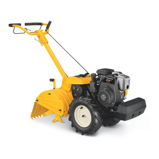
Rear Tine Tiller – Model RT 65
IMPORTANT
READ SAFETY RULES AND INSTRUCTIONS CAREFULLY BEFORE OPERATION
Warning: This unit is equipped with an internal combustion engine and should not be used on or near any unimproved forest-covered, brush-
covered or grass-covered land unless the engine's exhaust system is equipped with a spark arrester meeting applicable local or state laws (if any).
If a spark arrester is used, it should be maintained in effective working order by the operator. In the State of California the above is required by law
(Section 4442 of the California Public Resources Code). Other states may have similar laws. Federal laws apply on federal lands. A spark arrester
for the muffler is available through your nearest engine authorized service dealer or contact the service department, P.O. Box 361131 Cleveland,
Ohio 44136-0019.
PRINTED IN U.S.A
FORM NO. 769-01671C
CUB CADET LLC, P.O. BOX 361131 CLEVELAND, OHIO 44136-0019
12/15/2006
Advertisement
Table of Contents

Related Manuals for Cub Cadet 21AB455C710


Summary of Contents for Cub Cadet 21AB455C710
- Page 1 (Section 4442 of the California Public Resources Code). Other states may have similar laws. Federal laws apply on federal lands. A spark arrester for the muffler is available through your nearest engine authorized service dealer or contact the service department, P.O. Box 361131 Cleveland, Ohio 44136-0019. PRINTED IN U.S.A FORM NO. 769-01671C CUB CADET LLC, P.O. BOX 361131 CLEVELAND, OHIO 44136-0019 12/15/2006...
-
Page 2: Table Of Contents
You can locate the model plate by looking at the rear of the tine shield. This information is important for use when communi- CUB CADET LLC cating with an authorized service dealer. P. O. BOX 361131 www.cubcadet.com... - Page 3 Safety Labels WARNING WARNING Hot surfaces can Hot surfaces can cause severe burns. cause severe burns. Do not touch Do not touch WARNING muffler or muffler or adjacent areas. adjacent areas. This symbol points out important safety instructions which, if not followed, could WARNING WARNING...
-
Page 4: Safe Operation Practices
WARNING: Engine Exhaust, some of its constituents, and certain vehicle components contain or emit chemicals known to State of California to cause cancer and birth defects or other reproductive harm. DANGER: This machine was built to be operated according to the rules for safe operation in this manual. - Page 5 Maintenance & Storage • After striking a foreign object, stop the engine, disconnect the spark plug wire and ground against • Never tamper with safety devices. Check their the engine Thoroughly inspect the machine for any proper operation regularly. damage. Repair the damage before starting and •...
-
Page 6: Assembling Your Tiller
NOTE: References to right or left side of the tiller are Hex Bolt determined from behind the unit in the operating position. Flat Washer To Remove Unit From Carton Hairpin Clip T-Knob • Remove staples, break glue on top flaps, or cut tape Clevis Pin at carton end and peel along top flap to open carton. - Page 7 Attaching Control Rod Slot Head Screw, Nut, & Flat Washers • Make sure the handle assembly is in the highest position. Refer to Know Your Tiller section. Internally • Remove hairpin clips from control rod, (rubber Threaded Tube washers to remain on control rod). •...
-
Page 8: Know Your Tiller
Clutch Control Gear Selection Handle Handle Adjustment Lock Know Your Tiller Depth Stake WARNING Make certain unit is in NEUTRAL when starting the engine. Figure 4-1 Gear Selection Handle IMPORTANT: Use the reverse tine drive when tilling virgin ground, sod, or hard soil. Use the forward tine drive The gear selection handle is located in the center of when cultivating or tilling soft ground. - Page 9 Clutch Control The clutch control is located beneath the handle. Squeezing the clutch control against the handle engages the wheel and tine drive mechanisms. NOTE: Never engage clutch lever while shifting. Know Your Handle Adjustment Lock Tiller The handle may be adjusted to the height desired. Loosen the handle height adjustment lock a few turns.
-
Page 10: Operating Your Tiller
Setting The Depth WARNING: Read, understand, and follow all instructions and warnings on the ma- Tilling depth is controlled by the depth stake which can be chine and in this manual before operating. adjusted to five different settings. Adjust the side shields Before Starting as you adjust the depth stake. -
Page 11: Making Adjustments
Belt Tension Adjustment To adjust the depth stake, remove the clevis pin and hairpin clip. Move the depth stake to the desired setting and Periodic adjustment of the belt tension may be required secure with the clevis pin and hairpin clip. See Figure 7. due to normal stretch and wear on the belt. -
Page 12: Maintaining Your Tiller
Cleaning Tine Area WARNING: Disconnect the spark plug wire and ground it against the engine Clean the underside of the tine shield after each use. before performing any repairs. The dirt washes off the tines easier if rinsed off im- Engine mediately instead of after it dries. -
Page 13: Troubleshooting
• Clean the exterior of engine and the entire tiller Idler Pulley Rod thoroughly. Lubricate the tiller as described in the lubrication instructions. • We do not recommend the use of pressure washers to clean your unit. They may cause damage to electric components, spindles, pulleys, bearings or Trouble the engine. - Page 14 19 49...
-
Page 15: Parts Lists
Tine Idler Gear Ass’y: 30T parts, contact your 736-0351 Fl-Wash.76” I.D. x 1.5” O.D. 617-0060 Tine Input Sprocket Ass’y: 9T local Cub Cadet dealer; 736-0407 Bell-Wash .45” I.D. x 1.0” 617-0061 Wheel Input Sprocket Ass’y: 10T or call our dealer 736-0518 Thrust Wash. - Page 17 712-3054 Hex Nut 3/8-24 parts, contact your 735-0246A Plug 742-0305 13” Articulating Tine local Cub Cadet dealer; 736-0117 Flat Washer 3/8 ID x .620 OD 738-0689 Shoulder Bolt or call our dealer 736-0242 Bell Washer .340 ID x .872 OD 736-0208 Flat Washer .51”...
- Page 18 Wheel shaft shown for reference only...
- Page 19 Idler Belt Keeper parts, contact your 710-0723 Hex Cap Screw 3/8-16 x 1.25 634-04231 Wheel Assembly 16.0 x 4.6 x 8 local Cub Cadet dealer; 712-0266 Lock Jam Nut 3/8-16 734-0808 Tire Only 16.2 x 4.6 or call our dealer...
-
Page 20: Warranty
MANUFACTURER’S LIMITED WARRANTY FOR The limited warranty set forth below is given by Cub Cadet LLC with e. Replacement parts that are not genuine Cub Cadet parts. respect to new merchandise purchased and used in the United States, its f. Service completed by someone other than an authorized service possessions and territories.