Table of Contents
Advertisement
Quick Links
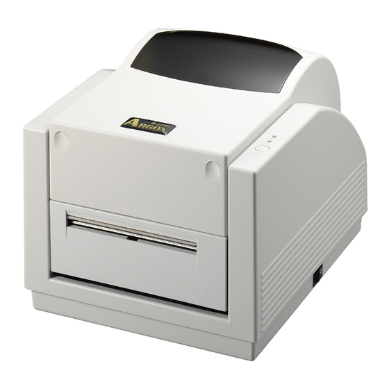
A-2240, A-2240E
Desktop Barcode Printer
User's Manual
Proprietary Statement
This manual contains proprietary information of Argox Information Co., Ltd. It is
intended solely for the information and use of parties operating and maintaining
the equipment described herein. Such proprietary information may not be used,
reproduced, or disclosed to any other parties for any other purpose without the
expressed written permission of Argox Information Co., Ltd.
Product Improvements
Continuous improvement of products is a policy of Argox Information Co., Ltd. All
specifications and signs are subject to change without notice.
FCC Compliance Statement
This equipment has been tested and found to comply with the limits for a Class A
digital device, pursuant to Part 15 of the FCC Rules. These limits are designed
to provide reasonable protection against harmful interference in a residential
installation. This equipment generates, uses, and can radiate radio frequency
energy and, if not installed and used in accordance with the instructions, may
cause harmful interference to radio communications. However, there is no
guarantee that the interference will not occur in a particular installation. If this
equipment does cause harmful interference to radio or television reception,
which can be determined by turning the equipment off and on, the user is
encouraged to try to correct the interference by the following measures:
Reorient or relocate the receiving antenna.
Increase the separation between the equipment and the receiver.
Connect the equipment into a different outlet on a different circuit.
Consult the dealer or an experience Radio/TV technician for help.
This unit was tested with shielded cables on the peripheral devices. Shielded
cables must be used with the unit to insure compliance. The user is cautioned
that any changes or modifications not expressly approved by Argox Information
Co., Ltd. could void the user's authority to operate the equipment.
CE Statement of Conformity
This products is herewith confirmed to comply with the requirements set out in
the Council Directive on the Approximation of the laws of the Member States
relating to Electromagnetic Compatibility Directive (2004/108/EC).
evaluation regarding EMC, the following standard was applied:
RFI Emission:
EN 55022: 2006 + A1: 2007 Class A
EN 61000-3-2: 2006
For the
2
Advertisement
Table of Contents

Related Manuals for Argox A-2240


Summary of Contents for Argox A-2240
- Page 1 A-2240, A-2240E Desktop Barcode Printer Product Improvements Continuous improvement of products is a policy of Argox Information Co., Ltd. All specifications and signs are subject to change without notice. FCC Compliance Statement This equipment has been tested and found to comply with the limits for a Class A digital device, pursuant to Part 15 of the FCC Rules.
-
Page 2: Table Of Contents
Peel Off Mode ................. 24 loss) arising out of the use of or the results of use of or inability to use such product, even if Argox Information Co., Ltd. has been advised of the possibility of Cutter Mode..................29 such damages. -
Page 3: Getting Started
Important notice during TPH replacement......... 72 Getting Started Technical Reference ..............73 General Specifications............73 Congratulations on choosing the Argox Amigo Series Fonts, Bar Codes and Graphics Specification....... 76 desktop barcode printer. This user’s manual will help you get Printer Programming Language A, PPLA........76 to know your new printer. -
Page 4: Package Contents
Printer Connecting the Power Supply Sample Media Connect the power supply as below. Ribbon WARNING: 1. do not operate the printer and power supply in an area where they might get wet. 1. Make sure the power switch is in the "O" position. 2. -
Page 5: Getting To Know Your Printer
Getting to Know Your Printer The illustrations that follow describe the printer’s parts, features, controls, and indicators. Parts and Features Ready Indicator Top Cover Power Indicator Power Cord Feed Button Power Switch... -
Page 6: Controls And Indicators
Controls and Indicators The printer’s controls and indicators are shown in the diagram Media Hanger below. The following table explains control and indicator functions. Release Levers Ready Indicator Top Cover Power Indicator Ribbon Pick-up Holder Ribbon Supply Holder Thermal Printhead Feed Button Power Switch... -
Page 7: Loading Ribbon And Media
Control / Loading Ribbon and Media Function Indicator On: turns on normal operation This section describes how to load ribbon and media in the Amigo Power Switch Series printers. Off: turns off power Note: Turn power off before connecting or Loading a Ribbon disconnecting cables Green light shows printer power on... - Page 8 4. Unwrap the ribbon roll pack and separate the ribbon roll and the bare core. 5. Attach the edge of the ribbon on the bare core and wind it a Media Compartment little bit onto the core. 6. Insert the ribbon roll into the supply holder. (First snap in the Release Lever right side and then the left side.) Ribbon Roll...
- Page 9 7. Turn back the print head module and then insert the bare core 8. Turn the wheel of the print head module to ensure the ribbon is into the pick-up holder. (First snap in the right side, then the lift tightly wound.
-
Page 10: Loading Media
2. Remove the media hanger. Loading Media 3. Load the media roll onto the hanger. 4. Unlatch the print head module. The Amigo Series printers offer three different loading modes: standard, peel-off, or with a cutter. 5. Open the front cover to allow the labels pass through the slot. Standard mode allows you to collect each label freely. - Page 11 6. Lead the labels through the media guides with the other hand. 7. Press the print head module down firmly on both sides until you The media guide can be adjusted centrally to fit with different hear a snap. label widths. Print Head Module Media Guides...
-
Page 12: Peel Off Mode
Peel Off Mode 8. Close the top cover and turn on the printer or press the feed button if the printer is already on. 1. Unscrew the two screws behind the front cover. 2. Remove the front cover. Screw Feed Button... - Page 13 3. Plug in the dispenser connecter. 5. Secure the two screws behind the front cover. 4. Mount the dispenser module. 6. Lead the labels through the media guides and dispenser. Dispenser Connecter Screws Media Guides Dispenser Module Dispenser...
- Page 14 7. Press down the print head module firmly until you hear 9. Press the feed button and the label backing paper will come out from the slot under dispenser. a snap. 8. Close the top cover and turn on the printer or press the feed button if the printer is already on.
-
Page 15: Cutter Mode
4. Loose the 2 screws on the printer bottom. Cutter Mode Note: For cutter mode you must first install the cutter and cutter baby board to J16 on the main board 1. Turn off the POWER switch. 2. Unscrew the two screws behind the front cover. 3. - Page 16 7. Remove the whole print head assembly by releasing the 4 screws at its feet. 8. Plug the cutter baby board to J16 on the main board.
- Page 17 12. Plug in the cutter connecter 9. Reattach the print head assembly by securing the 4 screws and pull the front side of "Middle Cover" to put it back. 10. Screw the 2 screws on the printer bottom. 11. Unscrew the screw on the printer module. 12.
- Page 18 Print Head 14. Lead the label through the media guides and cutter slot. Note: The feed button does not make the printer cut. Cutting 15. Press down the print head module firmly on both sides until occurs only when the software is properly set. you hear a snap.
-
Page 19: Configuration And Configuration
Configuration and Configuration Retuning to Factory Default Settings 1. Turn on the printer and wait for 5 or more seconds. This section discusses calibration, printing configuration and 2. Press the "Feed" button for 10 seconds, and the "Ready" resetting the printer to factory defaults. indicator and "Power"... -
Page 20: Computer Connections
Computer Connections Serial (RS-232) Interface Requirements Note: You must insert the power supply’s barrel connector The required cable must have a nine-pin "D" type male connector on one end, which is plugged into the mating serial port located into the power jack on the back of the printer before on the back of the printer. -
Page 21: Ethernet 10/100 Internal Printer Server Option
Ethernet 10/100 Internal Printer Server Option This connector is for Ethernet application; it is convenient to use several printers by Ethernet connector at the same time. Notes: When using Ethernet model printer, please wait till the Ready Indicator to stop blinking and then can start to use printer. Power Cord Power Cord... -
Page 22: Communicating With The Printer
Ethernet Status/Activity Indicators Communicating with the Printer LED Status Description The bundled printer driver can be applied to all applications under Both Off No Ethernet link detected Windows 2000/2003/Windows XP and Windows Vista and Speed LED support 32/64 bits version. With this driver you can run any Green LED On: 100 Mbps link Off: l0 Mbps link popular Windows software applications such as MS-Word and... -
Page 23: Installing The Printer Driver (Argox Seagull Driver)
4. Click "Finish". Installing the Printer Driver (Argox Seagull Driver) 1. Double click the driver file (Argox Seagull driver) to execute the installation. 2. Windows Printer Driver…..Select I accept and Click "Next" 5. Select Install printer drivers and Click "Next"... - Page 24 6. Select a driver for your printer and click "Next". 8. Select the port of the printer and click "Next" 9. Enter Printer name (i.e. Argox A-2240 PPLB) and select 7. Select model & emulation: A-2240 PPLB "do not share this printer”, and Cli...
- Page 25 10. Checking all the data on the showing screen, if data corrected, 12. After the installation is complete click " Close" click "Finish" 11. After the related files have been copied to your system, click "Finish"...
-
Page 26: Driver For Plug And Play (Usb Only)
Driver for Plug and Play (USB only) 5. Select “Search for the best driver in these locations” and choose “Include this location in the search”. Input the 1. Extract the PrinterDriver.exe to the fixed route. location of the printer driver, click “Next”. (“C:\Seagull) 2. - Page 27 6. Select “Continue Anyway”. 7. Click “Finish”.
-
Page 28: Driver For Win Vista (Usb Only)
Driver for WIN Vista (USB only) 8. The Argox A-2240E PPLB printer is added in “Printers 1. Extract the PrinterDriver.exe to the fixed route. and Faxes”. (“C:\Seagull) 9. Reboot the system. 2. Connect the label printer to a computer with a USB 10. - Page 29 6. Select “I don’t have the disk. Show me the other options.” 7. Select “Browse my computer for driver software (advanced) “.
- Page 30 8. Input the location of printer driver. (“C:\Seagull) 9. Select” Install this driver software anyway” 10. The related files start to copy to your system.
-
Page 31: Troubleshooting
11. After the installation is complete, click “Close”. Troubleshooting Normally, when the printer is in not working properly, the "Power" LED blinks continuously, and printing and communication between the host and printer stops. LED Diagnosis If the Power and Ready LEDs are blinking, it means you may have a problem. - Page 32 LED Indicators: Only the Ready LED blinks LED Indicators: Power and Ready LEDs blink alternately Power LED Ready LED Power LED Ready LED Possible Problems Solutions Remarks Possible Problems Solutions Remarks Print head too hot Printing will stop until Ribbon out Supply the ribbon roll Not applicable to direct...
-
Page 33: Miscellaneous
Poor printout quality: Miscellaneous The ribbon may not be qualified. The media may not be qualified. If the host shows "Printer Time out" 1. Check if the communication cable (serial) is connected Adjust the Darkness (heat temperature). ... -
Page 34: Caring For Your Printer
TPH Cleaning Interval: Caring for Your Printer It’s strongly recommended to regularly clean print heads at least when changing every one ribbon roll (in thermal transfer Adhesives and coatings of media can over time transfer onto the printing mode), or every one label roll (in direct thermal printing printer components along the media path including the thermal mode). -
Page 35: Replacing Thermal Print Head
Replacing Thermal Print Head Turn off the power and wait for both LEDs to go off. Push the print head module and pull it down as shown by the two arrows below. This releases the print head module from the printer chassis. Push Special Caution: Warranty of print heads will be void if print head serial number... -
Page 36: Important Notice During Tph Replacement
Loosen the 2 screws(C) and take off COVER-TPH(79) Important notice during TPH replacement Unplug the 2 print head cables from the connectors on the 1. Heater line should NOT be touched by bare hands to old TPH-module. prevent any damage caused by ESD or corrosion. Plug the 2 print head cable to the new TPH-module. -
Page 37: Technical Reference
A/B/C, UCC/EAN-128, General Specifications UCC/EAN-128 K-MART, UCC/EAN-128 , Random Weight, Plessey, HBIC, Telepen, FIM, UPC2, UPC5, GS1 Data Bar A-2240 A-2240E Specificatio PPLB: Code 39 (standard/with checksum digit),Code 93 Printing method Direct Transfer/Thermal Transfer Interleaved 2 of 5 (standard/with checksum digit/with human... -
Page 38: Fonts, Bar Codes And Graphics Specification
Ribbon Width: 1”~4” Ribbon roll – max OD: 1.45”(37mm) Fonts, Bar Codes and Graphics Specification Ribbon Length: max 100m Ribbon Core size – ID: 0.5”(13mm) with notch Wax, Wax/Resin, The specifications of fonts, bar codes and graphics depends on Resin (Outside Ribbon) Dimensions W 200mm x H 170mm x L 245mm the printer emulation. -
Page 39: Printer Programming Language B, Pplb
Printer Programming Language B, PPLB Printer Programming Language Z, PPLZ Programming Programming PPLB PPLZ Language Language Internal fonts 5 fonts with different point size 8 (A~H) fonts with different point size. 8 AGFA fonts: 7 (P~V) fonts with fixed different 8 bits code page : 437, 850, 852, 860, 863, 865, Internal fonts point size (can’t scale). -
Page 40: Interface Specifications
Notes: Interface Specifications 1. The bare core for the ribbon must be 11 cm in length. It USB Interface should have two opposite slits at two ends. If the ribbon itself is less than 11 cm, it must be aligned with the bare This is port complies with USB 2.0 Full Speed. -
Page 41: Serial
Serial Ethernet The RS232 connector on the printer side is a female, DB-9. The following port complies with Ethernet communication. Direction Definition Signal Shorted to Pin 6 Transmit+ RxData Transmit- TxData Receive+ N.C. Reserved Ground Reserved Shorted to Pin 1 Receive- Reserved Reserved... -
Page 42: Connection With Host
Connection with host Printer Terminal/Host Pin 2- RxData ……… TxData Pin 3- TxData ……… RxData Host 25S Printer 9P Host 9S Printer 9P Pin 5- Ground ……… Ground (PC or compatible) (PC or compatible) In general, as long as the data quantity is not too large and you DTR 20 ……... -
Page 43: Appendix I - Installing The Extension Card
Appendix I - Installing the Extension Card 4. Remove the middle cover. Extension Card designated for all optional extension modules. For example, RTC card and Add-on card. Install the extension card into the printer as follows: 1. Turn off the printer power. 2. - Page 44 5. Mount the extension card to J14 on the main board. 6. Click back the middle cover. 7. Secure the two screws for the base housing. 8. Click the top cover into place.