Heatilator NDV3630 Owner's Manual Installation And Operation
Hide thumbs
Also See for NDV3630:
- Owner's manual (88 pages) ,
- Specification (4 pages) ,
- Owner's manual (84 pages)
Table of Contents
Advertisement
Quick Links
Model(s):
NDV3630, NDV3933, NDV4236, NDV4842,
NDV3630I, NDV3933I, NDV4236I, NDV4842I,
NDV3630L, NDV3933L, NDV4236L, NDV4842L,
NDV3630IL, NDV3933IL, NDV4236IL, NDV4842IL
• Important operating
a n d m a i n t e n a n c e
instructions included.
WARNING: If the information in these
instructions is not followed exactly, a fi re
or explosion may result causing property
damage, personal injury, or death.
• DO NOT store or use gasoline or other fl am-
mable vapors and liquids in the vicinity of this
or any other appliance.
• What to do if you smell gas
- DO NOT try to light any appliance.
- DO NOT touch any electrical switch. DO
NOT use any phone in your building.
- Immediately call your gas supplier from a
neighbor's phone. Follow the gas suppli-
er's instructions.
- If you cannot reach your gas supplier, call
the fi re department.
• Installation and service must be performed
by a qualifi ed installer, service agency, or the
gas supplier.
In the Commonwealth of Massachusetts installation must be
performed by a licensed plumber or gas fi tter.
See Table of Contents for location of additional Commonwealth
of Massachusetts requirements.
Installation and service of this appliance should be
performed by qualifi ed personnel. Hearth & Home
Technologies suggests NFI certifi ed or factory trained
professionals, or technicians supervised by an NFI
certifi ed professional.
NOTICE
DO NOT DISCARD THIS MANUAL
• Read, understand and follow
these instructions for safe
installation and operation.
Heatilator • Novus NDV Series • 4055-187 Rev. AA • 10/13
Owner's Manual
Installation and Operation
• Leave this manual with
party responsible for use
and operation.
WARNING
DO NOT TOUCH GLASS
NEVER ALLOW CHILDREN
A barrier designed to reduce the risk of burns
from the hot viewing glass is provided with this
appliance and shall be installed.
This appliance may be installed as an OEM
installation in manufactured home (USA
only) or mobile home and must be installed
in accordance with the manufacturer's
instructions and the Manufactured Home
Construction and Safety Standard, Title 24
CFR, Part 3280 in the United States, or the
Standard for Installation in Mobile Homes,
CAN/CSA Z240 MH Series, in Canada.
This appliance is only for use with the type(s)
of gas indicated on the rating plate. This
appliance is not convertible for use with other
gases, unless a certifi ed kit is used.
HOT GLASS WILL
CAUSE BURNS.
UNTIL COOLED.
TO TOUCH GLASS.
1
Advertisement
Table of Contents

Related Manuals for Heatilator NDV3630


Summary of Contents for Heatilator NDV3630
- Page 1 Technologies suggests NFI certifi ed or factory trained appliance is not convertible for use with other professionals, or technicians supervised by an NFI gases, unless a certifi ed kit is used. certifi ed professional. Heatilator • Novus NDV Series • 4055-187 Rev. AA • 10/13...
-
Page 2: Congratulations
As the owner of a new fi replace, you’ll want to read and Your new Heatilator gas fi replace will give you years of carefully follow all of the instructions contained in this durable use and trouble-free enjoyment. Welcome to the Owner’s Manual. -
Page 3: Table Of Contents
B. Constructing the Appliance Chase Junction Box Installation C. Clearances G. Wall Switch Installation for Fan (Optional) D. Mantel and Wall Projections 6 Termination Locations A. Vent Termination Minimum Clearances Heatilator • Novus NDV Series • 4055-187 Rev. AA • 10/13... - Page 4 B. Intellifi re Ignition System 17 Reference Materials A. Appliance Dimension Diagram B. Vent Components Diagrams C. Service Parts D. Optional Components E. Contact Information = Contains updated information. Heatilator • Novus NDV Series • 4055-187 Rev. AA • 10/13...
-
Page 5: Limited Lifetime Warranty
3 years Firebox and heat exchanger Lifetime All replacement parts 90 Days beyond warranty period See conditions, exclusions, and limitations on next page. 4021-645F 02-18-13 Page 1 of 2 Heatilator • Novus NDV Series • 4055-187 Rev. AA • 10/13... - Page 6 THE EXTENT PROVIDED BY LAW, HHT MAKES NO EXPRESS WARRANTIES OTHER THAN THE WARRANTY SPECIFIED HEREIN. THE DURATION OF ANY IMPLIED WARRANTY IS LIMITED TO DURATION OF THE EXPRESSED WARRANTY SPECIFIED ABOVE. 4021-645F 02-18-13 Page 2 of 2 Heatilator • Novus NDV Series • 4055-187 Rev. AA • 10/13...
-
Page 7: Listing And Code Approvals
A 110-120 VAC circuit for this product must be protected with ground-fault circuit-interrupter protection, in compliance with the applicable electrical codes, when it is installed in locations such as in bathrooms or near sinks. Heatilator • Novus NDV Series • 4055-187 Rev. AA • 10/13... -
Page 8: Requirements For The Commonwealth Of
(1/2) inch in size, “GAS See Gas Connection section for additional Common- VENT DIRECTLY BELOW. KEEP CLEAR OF ALL OB- wealth of Massachusetts requirements. STRUCTIONS”. Heatilator • Novus NDV Series • 4055-187 Rev. AA • 10/13... -
Page 9: User Guide
Failure to operate fi replace according to operating instructions could cause fi re or injury. HEARTH CLEAR SPACE (not required) SECTION 2 Figure 2.1 General Operating Parts Heatilator • Novus NDV Series • 4055-187 Rev. AA • 10/13... -
Page 10: Fan Kit (Optional)
For more information refer to the instructions supplied with your decorative door or front. Red or Black Button Figure 2.3 Ignitor Button Heatilator • Novus NDV Series • 4055-187 Rev. AA • 10/13... -
Page 11: Lighting Instructions (Ipi)
See installation and operating instructions accompanying appliance. For additional information on operating your Hearth & Home Technologies fi replace, please refer to www.fi replaces.com. Final inspection by Heatilator • Novus NDV Series • 4055-187 Rev. AA • 10/13... -
Page 12: Lighting Instructions (Standing Pilot)
Hearth & Home Technologies fi replace, please refer to www.fi replaces.com. 4. Push in gas control knob slightly and turn clock- wise to OFF”. DO NOT force. 5. Close control access panel. Final inspection by 464-903H Heatilator • Novus NDV Series • 4055-187 Rev. AA • 10/13... -
Page 13: After Appliance Is Lit
fl ame burn continually? Some optional control systems available with IPI models may allow pilot fl ame to remain lit. In a standing pilot system the pilot will always stay on. Heatilator • Novus NDV Series • 4055-187 Rev. AA • 10/13... -
Page 14: Maintenance And Service
Carefully set fi xed glass assembly in place on appliance. Hold glass in place with one hand and secure glass latches with the other hand. • Reinstall door or decorative front. Heatilator • Novus NDV Series • 4055-187 Rev. AA • 10/13... -
Page 15: Maintenance Tasks-Service Technician
Inspect for paint condition, warped surfaces, corrosion or perforation. Sand and repaint as necessary. • Replace appliance if fi rebox has been perforated. Control Compartment and Firebox Top Frequency: Annually By: Service Technician Heatilator • Novus NDV Series • 4055-187 Rev. AA • 10/13... - Page 16 (Either cobrahead or SIT) Figure 3.1 IPI Flame Patterns Figure 3.2 Standing Pilot Flame Patterns Heatilator • Novus NDV Series • 4055-187 Rev. AA • 10/13...
-
Page 17: Installer Guide
FRAMING/HEADER (SECTION 5) OPTIONAL WALL SWITCH (SECTION 13) MANTEL AND MANTEL LEG (SECTION 5 & 14) SURROUND (SECTION 14) GAS LINE (SECTION 12) Figure 4.1 Typical Appliance System Heatilator • Novus NDV Series • 4055-187 Rev. AA • 10/13... -
Page 18: Design And Installation Considerations
Manometer Flat blade screwdriver 1/2 - 3/4 inch length, #6 or #8 Self-drilling screws Caulking material (300ºF minimum continuous exposure rating) One 1/4 inch female connection (for optional fan). Heatilator • Novus NDV Series • 4055-187 Rev. AA • 10/13... -
Page 19: Framing And Clearances
19- /8 4 - /8 -1/4 10 7 1102 1194 1092 4842 41-7/8 19- /8 4 - /8 -1/4 1219 10 4 1102 1194 Figure 5.1 Appliance Locations Heatilator • Novus NDV Series • 4055-187 Rev. AA • 10/13... -
Page 20: Constructing The Appliance Chase
19-5/8 in./498 mm 10 in./254 mm 9 in./229 mm 48 in./1219 mm 34-7/8 in./886 mm 19-5/8 in./498 mm 10 in./254 mm 9 in./229 mm NDV4842 Figure 5.2 Clearances to Combustibles Heatilator • Novus NDV Series • 4055-187 Rev. AA • 10/13... -
Page 21: Mantel And Wall Projections
Mantel Leg or Wall Projections (Acceptable on both 6-1/4 5-1/2 sides of opening) Measured from top of hood (in inches) Figure 5.3 Clearances To Mantels Or Other Combustibles Above Appliance Heatilator • Novus NDV Series • 4055-187 Rev. AA • 10/13... -
Page 22: Termination Locations
Over 18/12 to 20/12 Over 10/12 to 11/12 3.25 Over 20/12 to 21/12 * 3 ft. minimum in snow regions Figure 6.1 Minimum Height From Roof to Lowest Discharge Opening Heatilator • Novus NDV Series • 4055-187 Rev. AA • 10/13... - Page 23 Figure 6.3 Minimum Clearances for Terminations CAUTION: IF EXTERIOR WALLS ARE FINISHED WITH VINYL SIDING, IT IS SUGGESTED THAT A VINYL PROTECTOR KIT BE INSTALLED. Heatilator • Novus NDV Series • 4055-187 Rev. AA • 10/13...
-
Page 24: Vent Information And Diagrams
8-1/2 (216 mm) inches vertical (see chart) run. A length of straight pipe is allowed between two 45º elbows (see Figure 7.1). Figure 7.2 Pipe Effective Length Vertical 8-1/2 in. Horizontal Figure 7.1 Heatilator • Novus NDV Series • 4055-187 Rev. AA • 10/13... -
Page 25: Vent Diagrams
12 ft (3.66 m) min. 12 ft (3.66 m) min. 60 ft (18.29 m) max. 60 ft (18.29 m) max. Figure 7.3 Minimum Installation Requirements for Two 45° Elbows-Top Vent-Horizontal Termination Heatilator • Novus NDV Series • 4055-187 Rev. AA • 10/13... - Page 26 45° elbow installed horizontally. 25 ft/7.62 m (DVP) 25 ft/7.62m 25 ft/7.62m 23 ft/7.01 m (SLP) 25 ft/7.62m 25 ft/7.62m Installed Vertically Installed Horizontally Figure 7.5 Heatilator • Novus NDV Series • 4055-187 Rev. AA • 10/13...
- Page 27 Three Elbows 12 in./305 mm 24 ft/7.32 m (DVP) 19 ft/5.79 m 12 in./305 mm 22 ft/6.71 m (SLP) 19 ft/5.79 m Installed Vertically Figure 7.6 Heatilator • Novus NDV Series • 4055-187 Rev. AA • 10/13...
- Page 28 60 ft (18.29 m) max. Maximum horizontal run is 100% of vertical, but cannot exceed 26 ft (7.92 m) Figure 7.7d 31 ft to 60 ft Vertical Run Figure 7.8 Heatilator • Novus NDV Series • 4055-187 Rev. AA • 10/13...
- Page 29 45° elbow installed horizontally. Maximum horizontal run is 100% of vertical, but cannot exceed 26 ft (7.92 m) 12 ft (3.66 m) min. 60 ft (18.29 m) max. Figure 7.9 Heatilator • Novus NDV Series • 4055-187 Rev. AA • 10/13...
- Page 30 3. Rear Vent - Horizontal Termination (DVP only) No Elbow 18 in. (457 mm) max. Figure 7.10 One 45° Elbow 18 in. (457 mm) max. Figure 7.11 Heatilator • Novus NDV Series • 4055-187 Rev. AA • 10/13...
- Page 31 Subtract 1-1/2 ft (457 mm) from the total horizontal measurement for each 45° elbow installed horizontally. 1.22 0.61 1.83 1.83 0.91 2.74 2.44 1.22 3.66 Installed 2.44 1.52 4.57 Horizontally 2.44 1.83 5.49 Figure 7.13 Heatilator • Novus NDV Series • 4055-187 Rev. AA • 10/13...
- Page 32 12 ft (3.66 m) min. 6 ft (1.83 m) max. 60 ft (18.29 m) max. Maximum horizontal run is 100% of vertical, but cannot exceed 26 ft (7.92 m) Figure 7.15 Heatilator • Novus NDV Series • 4055-187 Rev. AA • 10/13...
- Page 33 6 ft (1.83 m) max. 12 ft (3.66 m) min. 60 ft (18.29 m) max. Maximum horizontal run is 100% of vertical, but can- not exceed 26 ft (7.92 m). Figure 7.16 Heatilator • Novus NDV Series • 4055-187 Rev. AA • 10/13...
-
Page 34: Vent Clearances And Framing
Top: 2-1/2 in. (64 mm) Bottom: 1/2 in. (13 mm) Sides: 1 in. (25 mm) Figure 8.1 Pipe Clearances Figure 8.2 Wall Penetration DVP Only Heatilator • Novus NDV Series • 4055-187 Rev. AA • 10/13... -
Page 35: Install The Ceiling Firestop
INSTALL ATTIC INSULATION SHIELDS BEFORE OR AFTER INSTALLATION OF VENT SYSTEM 3 FASTENERS PER SIDE CEILING FIRESTOP CEILING FIRESTOP INSTALLED BELOW CEILING INSTALLED ABOVE CEILING Figure 8.4 Installing the Attic Shield Heatilator • Novus NDV Series • 4055-187 Rev. AA • 10/13... -
Page 36: Install Attic Insulation Shield
Bend all tabs inward 90° around the top of the shield. These tabs must be used to prevent blown insulation from getting between the shield and vent pipe, and to maintain air space clearance. Heatilator • Novus NDV Series • 4055-187 Rev. AA • 10/13... -
Page 37: Appliance Preparation
Figure 9.3 • Attach the fi rst vent section. It will snap into place. • Cut the metal retaining band and fold the sides out. Proceed to Section 9.C. Heatilator • Novus NDV Series • 4055-187 Rev. AA • 10/13... -
Page 38: Rear Vent
Figure 9.11 • Attach the fi rst vent section (it will snap into place). Slide the insulation gasket onto the vent section, up against the appliance and over the tabs. Heatilator • Novus NDV Series • 4055-187 Rev. AA • 10/13... -
Page 39: Secure And Level The Appliance
Secure the appliance to the framing by using nails or screws through the nailing tabs. • Secure the appliance to the fl oor by inserting two screws through the pilot holes at the bottom of the appliance. Heatilator • Novus NDV Series • 4055-187 Rev. AA • 10/13... -
Page 40: Installing Vent Pipe
fl ue at the horizontal elbow joint to prevent the elbow from rotating. Use screws no longer than 1/2 in. (13 mm). If predrilling screw holes, DO NOT penetrate in- ner pipe. INCORRECT Figure 10.4 Seams Heatilator • Novus NDV Series • 4055-187 Rev. AA • 10/13... -
Page 41: Assemble Vent Sections (Slp Pipe Only)
• Only outer pipes are sealed, sealing the inner fl ue is not required. • All unit collar, pipe, slip section, elbow and cap outer fl ues shall be sealed. Heatilator • Novus NDV Series • 4055-187 Rev. AA • 10/13... -
Page 42: Secure The Vent Sections
Figure 10.10 Rotate Seams for Disassembly Figure 10.11 Align and Disassemble Vent Sections Figure 10.8 Securing Vertical Pipe Sections Figure 10.9 Securing Horizontal Pipe Sections Heatilator • Novus NDV Series • 4055-187 Rev. AA • 10/13... -
Page 43: Install Decorative Ceiling Components (Slp Only)
fl aps and the roof. WARNING! Risk of Fire! Clean out ALL materials from inside the support box and complete the vertical vent run Figure 10.13 and termination. Heatilator • Novus NDV Series • 4055-187 Rev. AA • 10/13... -
Page 44: Install Metal Roof Flashing
• Caulk the perimeter of the fl ashing where it contacts the roof surface. See Figure 10.15. • Caulk the overlap seam of any exposed pipe sections that are located above the roof line. CAULK Figure 10.15 Figure 10.15 Heatilator • Novus NDV Series • 4055-187 Rev. AA • 10/13... -
Page 45: Install Vertical Termination Cap
Once the pipe section and the termination cap have been connected, slide the wall thimble up to the interior wall surface and attach with screws provided. See Figure 10.18. Figure 10.18 Wall Thimble Heatilator • Novus NDV Series • 4055-187 Rev. AA • 10/13... -
Page 46: Install Horizontal Termination Cap
SLP-TRAP2 can adjust 4 in. (5 1/4 to 9 1/4)) DVP-HPC1 can adjust 2 1/8 in. (4 1/4 to 6 3/8) DVP-HPC2 can adjust 4 1/8 in. (6 3/8 to 10 1/2) Heatilator • Novus NDV Series • 4055-187 Rev. AA • 10/13... -
Page 47: Shrouds
19 x 19 Min. 483 x 483 Top Dim. Min. Top Dims. 16 x 16 406 x 406 Min. Base Dim. Min. Base Dim. Figure 11.1 Open Top Shroud Dimensions Heatilator • Novus NDV Series • 4055-187 Rev. AA • 10/13... - Page 48 20 x 20 508 x 508 Min. Height Minimum Height Minimum Opening Min. Opening Width Height Min. Opening Width Minimum Base Dimension Min. Opening Height Figure 11.2 Roofed Style Shroud Dimensions Heatilator • Novus NDV Series • 4055-187 Rev. AA • 10/13...
-
Page 49: Gas Information
2000 feet and 4500 feet. Above 4500 feet, • If substituting for these components, please consult consult local gas utility. local codes for compliance. Heatilator • Novus NDV Series • 4055-187 Rev. AA • 10/13... -
Page 50: Electrical Information
Wiring for optional Hearth & Home Technologies approved accessories should be done now to avoid reconstruction. Follow instructions that come with those accessories. Heatilator • Novus NDV Series • 4055-187 Rev. AA • 10/13... -
Page 51: Electrical Service And Repair
* GRN wire only used Pack with optional wall switch Pilot Assembly WSK-MLT-HTL Control Junction Wall Switch Adapter GRN* Valve Figure 13.3 Intellifi re Pilot Ignition (IPI) Wiring Diagram Heatilator • Novus NDV Series • 4055-187 Rev. AA • 10/13... -
Page 52: Junction Box Installation
(1/4 in. male) as shown. Figure 13.5 Junction Box Wired to Wall Switch or BC10 Heatilator • Novus NDV Series • 4055-187 Rev. AA • 10/13... -
Page 53: Finishing
1 in. (25 mm) min. to perpendicular wall 3-1/2 in. (89 mm) min. from fireplace opening to perpendicular wall Figure 14.2 Mantel Leg or Wall Projections (Acceptable on both sides of opening) Heatilator • Novus NDV Series • 4055-187 Rev. AA • 10/13... -
Page 54: Facing Material
Finish wall material may be combustible - Top and Sides 0 in. 0 in. 0 in. High Temperature Sealant (300° F/149° C min.) Top and Side Seal Joint Figure 14.3 Non-combustible Facing Diagram Heatilator • Novus NDV Series • 4055-187 Rev. AA • 10/13... -
Page 55: Appliance Setup
Hearth & Home Technologies-approved optional acces- sories with this appliance. Using non-listed accessories could result in a safety hazard and will void the warranty. Figure 15.3 Remove Screen Package Heatilator • Novus NDV Series • 4055-187 Rev. AA • 10/13... -
Page 56: Place The Rockwool
• Some models may not require use of entire contents of bag. Close Open Figure 15.6 Adjusting Air Shutter Rockwool BURNER Lava Rock & Vermiculite Figure 15.5 Placement of Rockwool, Lava Rock and Vermiculite Heatilator • Novus NDV Series • 4055-187 Rev. AA • 10/13... -
Page 57: Remove Screen Protector
Figure 15.10 Installing Hood Figure 15.8 Remove Screen Protector M. Unpackage the Hood Remove parts package from appliance as shown in Fig- ure 5.9. HOOD Figure 15.9 Removing Hood Heatilator • Novus NDV Series • 4055-187 Rev. AA • 10/13... -
Page 58: Close The Screen Assembly
Open Figure 15.13 Rotate the Screen Down Figure 15.11 Magnetic Touch Latch Open Hang Screen on Shoulder Screws Figure 15.14 Press on Bottom of Screen Figure 15.12 Hang Screen Heatilator • Novus NDV Series • 4055-187 Rev. AA • 10/13... -
Page 59: Troubleshooting
With the pilot in the ON position, disconnect the thermopile leads from the valve. Take a reading at the thermopile leads. The reading should be 350 millivolts minimum. Replace the thermopile if the reading is below the minimum. Heatilator • Novus NDV Series • 4055-187 Rev. AA • 10/13... - Page 60 Ensure that no debris has been placed at the base of, or in the area of the air holes in the center of the base pan beneath the burner. Ensure that the glass is tightened properly on the unit, particularly on top corners. Heatilator • Novus NDV Series • 4055-187 Rev. AA • 10/13...
-
Page 61: Intellifi Re Ignition System
Verify module is securely grounded to metal chassis of appliance. D. Module voltage output / Valve/ Verify battery voltage is at least 2.7 volts. Replace batteries if Pilot solenoid ohms readings. voltage is below 2.7. Heatilator • Novus NDV Series • 4055-187 Rev. AA • 10/13... - Page 62 “I” from module. Place ON/OFF rocker switch or wall switch in ON position. If there is no spark at “I” terminal module must be replaced. If there is a spark at “I” terminal, module is fi ne. Heatilator • Novus NDV Series • 4055-187 Rev. AA • 10/13...
-
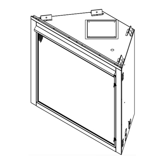
Page 63: Reference Materials
(203 mm) 15-3/4 in. (400 mm) 23-1/2 in. (597 mm) Model NDV3630 8 5/8 NDV3933 11 5/8 NDV4236 14 5/8 1041 NDV4842 20 5/8 1194 1067 Figure 17.1 Appliance Dimensions Heatilator • Novus NDV Series • 4055-187 Rev. AA • 10/13... -
Page 64: Vent Components Diagrams
(254 mm) 8 in. (203 mm) 14 in. (356 mm) 12 in. (305 mm) 5 in. (127 mm) DVP-WS DVP-HVS Wall Shield Firestop Vent Support Figure 17.2 DVP Vent Components Heatilator • Novus NDV Series • 4055-187 Rev. AA • 10/13... - Page 65 Flashing 13-7/8 in. 9-1/2 in. (352 mm) (241 mm) 26 in. (660 mm) 14 in. (356 mm) DVP-HSM-B Extended Heat Shield DRC-RADIUS Cap Shield Figure 17.3 DVP Vent Components Heatilator • Novus NDV Series • 4055-187 Rev. AA • 10/13...
- Page 66 1 in. (25 mm) 7-3/4 to 10-3/8 in. 1-5/8 in. (197 to 264 mm) (41 mm) DVP-FBHT DVP-HPC Fire Brick Termination Cap High Performance Cap Figure 17.4 DVP Vent Components Heatilator • Novus NDV Series • 4055-187 Rev. AA • 10/13...
- Page 67 12 in. 5-3/8 in. 9-3/8 in. Trap2 Effective (305 mm) 137 mm 238 mm Length DVP-TRAP Horizontal Termination Cap DVP-TRAP1 DVP-TRAPK1 DVP-TRAP2 DVP-TRAPK2 DVP-HPC1 DVP-HPC2 Figure 17.5 DVP Vent Components Heatilator • Novus NDV Series • 4055-187 Rev. AA • 10/13...
- Page 68 3° 87° 15 in. 10-1/2 in. (381 mm) 267 mm 10-7/8 in. 276 mm DVP-HRC-SS DVP-HRC-ZC-SS (Not approved for NDV4842) (Not approved for NDV4842) Figure 17.6 DVP Vent Components Heatilator • Novus NDV Series • 4055-187 Rev. AA • 10/13...
- Page 69 8-11/16 in. 1-1/2 in. 12 in. 5-1/2 in. 220 mm 38 mm 305 mm 146 mm SLP-WS SLP-FS Wall Shield Firestop Ceiling Firestop Figure 17.7 SLP Series Vent Components Heatilator • Novus NDV Series • 4055-187 Rev. AA • 10/13...
- Page 70 1 in. (25 mm) 13-1/2 in. 343 mm 7-3/4 to 10-3/8 in. (197 to 264 mm) DVP-FBHT SLK-SNKD Horizontal Snorkel Termination Cap Termination Cap Figure 17.8 SLP Series Vent Components Heatilator • Novus NDV Series • 4055-187 Rev. AA • 10/13...
- Page 71 (70 mm) 11-1/2 in. (292 mm) 12-1/4 in. (311 mm) 16 in. (406 mm) PVK-80 (For use with IPI and DSI appliances only.) Figure 17.9 SLP Series Vent Components Heatilator • Novus NDV Series • 4055-187 Rev. AA • 10/13...
-
Page 72: Service Parts
C. Service Parts Service Parts Beginning Manufacturing Date: Feb 2008 Novus Gas Fireplaces - DV Ending Manufacturing Date: Active Log Set Assembly Part number list on following page. 10/13 Heatilator • Novus NDV Series • 4055-187 Rev. AA • 10/13... - Page 73 Thumb Screws Pkg of 25 4021-558/25 Lava Rock Bag Assembly 4040-094 Lava Rock, 3 Lbs 4021-297 Mineral Wool 14333B Vermiculite 28746 Additional service part numbers appear on following page. Heatilator • Novus NDV Series • 4055-187 Rev. AA • 10/13...
- Page 74 Thumb Screws Pkg of 25 4021-558/25 Lava Rock Bag Assembly 4040-094 Lava Rock, 3 Lbs 4021-297 Mineral Wool 14333B Vermiculite 28746 Additional service part numbers appear on following page. Heatilator • Novus NDV Series • 4055-187 Rev. AA • 10/13...
- Page 75 Thumb Screws Pkg of 25 4021-558/25 Lava Rock Bag Assembly 4040-094 Lava Rock, 3 Lbs 4021-297 Mineral Wool 14333B Vermiculite 28746 Additional service part numbers appear on following page. Heatilator • Novus NDV Series • 4055-187 Rev. AA • 10/13...
- Page 76 Thumb Screws Pkg of 25 4021-558/25 Lava Rock Bag Assembly 4040-094 Lava Rock, 3 Lbs 4021-297 Mineral Wool 14333B Vermiculite 28746 Additional service part numbers appear on following page. Heatilator • Novus NDV Series • 4055-187 Rev. AA • 10/13...
- Page 77 Conversion Kit NG Conversion Kit LP DCKVP-NOVUS Pilot Orifi ce NG 593-528 Pilot Orifi ce LP 593-527 Regulator NG NGK-DXV Regulator LP LPK-DXV Additional service part numbers appear on following page. Heatilator • Novus NDV Series • 4055-187 Rev. AA • 10/13...
- Page 78 Orifi ce NG (#42C) 582-842 NDV4236 Orifi ce LP (0.058) 4021-602 Orifi ce NG (#37C) 582-837 NDV4842 Orifi ce LP (#52C) 582-852 Additional service part numbers appear on following page. Heatilator • Novus NDV Series • 4055-187 Rev. AA • 10/13...
- Page 79 582-843 NDV3933I Orifi ce LP (#54C) 582-854 Orifi ce NG (#42C) 582-842 NDV4236I Orifi ce LP (0.058) 4021-602 Orifi ce NG (#37C) 582-837 NDV4842I Orifi ce LP (#52C) 582-852 Heatilator • Novus NDV Series • 4055-187 Rev. AA • 10/13...
-
Page 80: Optional Components
LDS33 LDS46 1219 1829 LDSCP-M Shroud Leg Multipack (not shown) LDS-BV Decorative Shroud Catalog # 12.5 15.5 LDS-BV See your Heatilator dealer for a complete listing of optional components. Heatilator • Novus NDV Series • 4055-187 Rev. AA • 10/13... -
Page 81: Contact Information
5890485, 5941237, 6006743, 6019099, 6053165, 6145502, 6374822, 6484712, 6601579, 6769426, 6863064, 7077122, 7098269, 7258116, 7470729, 8147240 or other U.S. and foreign patents pending. 2000-945B Printed in U.S.A. - Copyright 2013 Heatilator • Novus NDV Series • 4055-187 Rev. AA • 10/13...