
Related Manuals for Grizzly G7945/46


Summary of Contents for Grizzly G7945/46
- Page 1 MODEL G7945/46 RADIAL DRILL PRESS OWNER'S MANUAL G7946 G7945 WARNING: NO PORTION OF THIS MANUAL MAY BE REPRODUCED IN ANY SHAPE OR FORM WITHOUT THE WRITTEN APPROVAL OF GRIZZLY INDUSTRIAL, INC.
-
Page 3: Table Of Contents
INTRODUCTION ... 2 SECTION 1: SAFETY ... 8 SECTION 2: CIRCUIT REQUIREMENTS ... 11 SECTION 3: SET UP ... 12 SECTION 4: OPERATIONS ... 22 Table of Contents SECTION 5: ACCESSORIES ... 29 SECTION 6: MAINTENANCE ... 31 SECTION 7: SERVICE ... 32 WARRANTY AND RETURNS ... -
Page 4: Introduction
INTRODUCTION Manual Accuracy Contact Info your machine may not exactly match the manual www.grizzly.com... - Page 5 Figures 1 & 2 Power Switch: Belt Tension Lock Knobs: Horizontal Adjustment Lever: Clamp Bolts: Crank Handle: Downfeed Handles: Depth Stop: Lash Screw: Torsion Spring: 10. Lock Pin: 11. Headstock Angle Tilt Scale: Figure 1. Identification ON/OFF Headstock Arbor Quill Spindle Figure 2.
-
Page 6: Machine Data Sheet
G7945 Machine Data Sheet Customer Service #: (570) 546-9663 · To Order Call: (800) 523-4777 · Fax #: (800) 438-5901 MODEL G7945 5 SPEED BENCH-TOP RADIAL DRILL PRESS Weight... 88 lbs. Length/Width/Height...33-1/2 x 11-1/2 x 31-1/2 in. Foot Print (Length/Width)... 13-1/2 x 8-1/2 in. - Page 7 Swing...34 in. Drilling Capacity... 1/2 in. in Steel No Of Spindle Speeds...5 Range Of Spindle Speeds...550, 880, 1520, 2490, 3470 RPM Drill Chuck Type... JT33 Key Chuck Drill Chuck Size... 5/8 in. Country Of Origin ... China Warranty ... 1 Year Serial Number Location ...Data Label on Head...
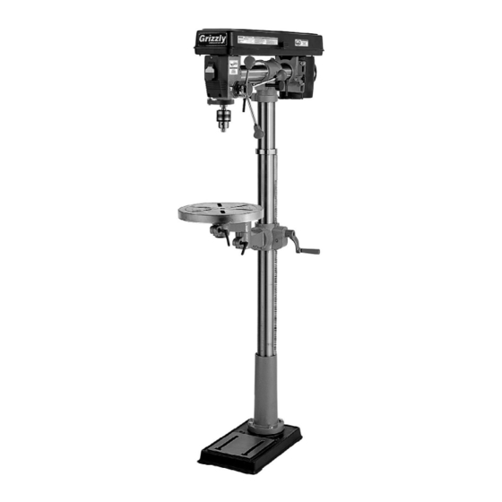
- Page 8 G7946 Machine Data Sheet Customer Service #: (570) 546-9663 · To Order Call: (800) 523-4777 · Fax #: (800) 438-5901 MODEL G7946 5 SPEED FLOOR RADIAL DRILL PRESS Weight... 138 lbs. Length/Width/Height... 32 x 14 x 64-1/2 in. Foot Print (Length/Width)... 18 x 11 in.
- Page 9 Swing... 33-1/2 in. Drilling Capacity... 1/2 in. in Steel No Of Spindle Speeds...5 Range Of Spindle Speeds...550, 880, 1520, 2490, 3470 RPM Drill Chuck Type... JT33 Key Chuck Drill Chuck Size... 5/8 in. Country Of Origin ... China Warranty ... 1 Year Serial Number Location ...Data Label on Head...
-
Page 10: Section 1: Safety
SECTION 1: SAFETY For Your Own Safety, Read Instruction Manual Before Operating this Machine The purpose of safety symbols is to attract your attention to possible hazardous conditions. This manual uses a series of symbols and signal words intended to convey the level of importance of the safety messages. -
Page 11: Safety Instructions For Machinery
Safety Instructions for Machinery 7. ONLY ALLOW TRAINED AND PROP- ERLY SUPERVISED PERSONNEL TO OPERATE MACHINERY. 8. KEEP CHILDREN/VISITORS 9. UNATTENDED OPERATION. 10. DO DANGEROUS ENVIRONMENTS. 11. KEEP WORK AREA CLEAN AND WELL LIGHTED. 12. USE A GROUNDED POWER SUPPLY RATED FOR THE MACHINE AMPERAGE. -
Page 12: Additional Safety For Drill Presses
Additional Safety for Drill Presses EYE/FACE/HAND PROTECTION. 2. SECURING BIT. 3. CORRECT BIT. 4. ADJUSTING KEYS AND WRENCHES. 5. DRILLING SHEET METAL. 6. SURFACE /WORKPIECE PREPARATION DAMAGED TOOLS. Like all machines there is danger associated with this machine. Accidents are frequently caused by lack of familiarity or failure to pay attention. -
Page 13: Section 2: Circuit Requirements
SECTION 2: CIRCUIT REQUIREMENTS 110V Operation Serious personal injury could occur if you connect the machine to power before com- pleting the setup process. DO NOT connect the machine to the power until instructed later in this manual. Electrocution or fire could result if machine is not grounded and installed in compliance with electrical... -
Page 14: Section 3: Set Up
SECTION 3: SET UP This machine presents serious injury hazards to untrained users. Read through this entire manu- al to become familiar with the controls and opera- tions before starting the machine! Wear safety glasses dur- ing the entire set up pro- cess! The Model G7945/G7946 is a heavy machine. - Page 15 Figures 4 & 5 Description Inventory Figure 4. Figure 5.
- Page 16 Hardware Recognition Chart...
-
Page 17: Site Considerations
Clean Up mum performance from your machine, make sure you clean all moving parts or sliding contact surfaces that are coated. Gasoline and petroleum products have low flash points and could cause an explosion or fire if used to clean machinery. DO NOT use gasoline or petroleum products to clean the machinery. - Page 18 Column and Base Components and Hardware Needed: To secure the column to the base: Figure 7 Figure 7. Table Bracket Components and Hardware Needed: To install the table bracket: Figure 8 Figure 9 Figure 8 Figure 9. Figure 10...
- Page 19 Figure 9 Figure 9 over-tighten the set screw or you may split the column ring. Also make sure the rack is seated firmly in the lower ring. Figure 10 Components and Hardware Needed: To install the column: Figure 10 Note: Do not Figure 11 Headstock Figure 11.
- Page 20 To install the downfeed handles: Figure 13 Figure 13. Drill Chuck and Arbor To assemble the drill chuck and mount it to the spindle, carefully follow the instructions below: to clean the mating surfaces may cause the tapered fit to loosen during operation,...
-
Page 21: Test Run
To test run the drill press: Troubleshooting Page 32 Bench Mounting glasses Components and Hardware Needed: starting To mount the G7945 drill press to a table: clothing Figure 15. Mounting Figure... -
Page 22: Floor Mounting
Figure 16 Figure 16. Mobile Base Mounting Figure 18 Drill presses are top-heavy and must be securely attached to a large-footprint base plate when used with a mobile base. Failure to use a base plate greatly increases pos- sibility of tipping and personal injury. -
Page 23: Recommended Adjustments
Note: Use 2" to 2 ⁄ " long hex bolts. Figure 18 Figure 18. Recommended Adjustments SECTION 7: SERVICE Factory adjustments that should be verified: Page 34 Page 34... -
Page 24: Section 4: Operations
OMMEND that you read books, trade maga- zines, or get formal training before begin- ning any projects. Regardless of the con- tent in this section, Grizzly Industrial will not be held liable for accidents caused by lack of training. Switch/Safety Key To use the switch: Figure 19. -
Page 25: Choosing Speeds
Choosing Speeds Using the Drill Bit Speed Chart Figure 20 Twist/Brad Point Drill Bits 1/16" – 3/16" 13/64" – 3/8" 25/64" – 5/8" 11/16" – 1" Spade/Forstner Bits 1/4" – 1/2" 9/16" – 1" 1-1/8" – 1-7/8" 2–3" Hole Saws 1/2"... -
Page 26: Changing Speeds
Changing Speeds To change speeds: Figure 21 Figure 21. Never operate drill press with pulley cover in the open position. Your hand may become trapped in the belt and serious personal injury will occur. - Page 27 For safe operation and optimum results, it is very important to follow these guidelines when drilling CLEARING CHIPS: SECURING WORKPIECE TO TABLE: PROTECTING TABLE: USING CORRECT SPEEDS: Drill Bit Speed Chart Page 23 LARGE DIAMETER BITS: SMALL DIAMETER BITS: HARD MATERIAL: SOFT MATERIAL: LUBRICANT:...
-
Page 28: Depth Stop
Depth Stop Depth Stop Figure 22. To set the depth stop: To set the spindle return distance: Note: The scale on the depth stop can be recali- brated if it gets moved or has changed since the factory setting. Refer to Depth Stop Calibration on Page 34 for instructions on how this is done. - Page 29 Table Tilt Step 2 Figure 24. Figure 25 Figure 25. Step 1 Figure 24 Table Rotation Note: The following steps only apply to the G7946.) Distance from Column (Note: The following steps only apply to the G7946. Figure 26. Figure 26...
- Page 30 Head Adjustments To tilt the headstock: Figure 27 Figure 27. To return to vertical position: Note: The lock pin is only intended to be a rough indexing tool. To adjust the headstock back and forth:...
-
Page 31: Section 5: Accessories
SECTION 5: ACCESSORIES G2500—20-PC Regular Sanding Drum Set Figure 28. G5753—Drill Press Vise 6" Figure 29. G8581— ⁄ " Keyless Drill Chuck JT #33 Figure 30. ® G5562—SLIPIT 1 Qt. Gel G5563—SLIPIT ® 12 oz Spray ® G2871—Boeshield T-9 12 oz Spray ®... - Page 32 H7196—Bifocal Safety Glasses 2.5 T20502 T20503 H7194 Figure 32. H2499—Small Half-Mask Respirator H3631—Medium Half-Mask Respirator H3632—Large Half-Mask Respirator H3635—Cartridge Filter Pair P100 Figure 33. G8865—Cobalt Alloy Drill Bits 13-PC. Set G8866—Steelex G8867—Steelex T20452 T20451 H0736 Figure 34. H9816—Power Twist Figure 35. ®...
-
Page 33: Section 6: Maintenance
SECTION 6: MAINTENANCE Unpainted Cast Iron Always disconnect power to the machine before performing maintenance. Failure to do this may result in serious person- al injury. General SECTION 5: ACCESSORIES Page 29 Lubrication V-Belts Changing Speeds Page 24 Cleaning... -
Page 34: Section 7: Service
SECTION 7: SERVICE Review the troubleshooting and procedures in this section to fix your machine if a problem develops. If you need replacement parts or you are unsure of your repair skills, then feel free to call our Technical Support at (570) 546-9663. - Page 35 Page 24 Drill Press Operations Page 34 Page 27...
-
Page 36: Depth Stop Calibration
Depth Stop Calibration To calibrate the depth stop: Figure 36. Figure 36. Feed Shaft Spring Tension Wear safety glasses and gloves when springs. Serious may occur if this warning is ignored! To adjust the feed shaft spring tension: Figure 37 Figure 37. -
Page 37: Electrical Components
Figure 38 Figure 38. A high tension coiled spring is underneath the cover. Put on heavy leather gloves to protect yours hands from possible lacera- tions when removing the cover. Electrical Components Figure 39. Note: It is important to keep a good grip during this step. - Page 38 Wiring Diagram G7945/G7946 Wiring Diagram...
- Page 39 G7945/G7946 Main Parts Breakdown...
- Page 40 G7945/G7946 Main Parts List PART # DESCRIPTION P7945008 GEAR PR16M EXT RETAINING RING 9MM PN03M HEX NUT M8-1.25 P7945015 KNOB BOLT M8-1.25 X 16 P7945016A MOUNT PLATE V2.06.06 P7945019B MOTOR 1/2HP 110V V2.3.07 19-1 P7945019-1 MOTOR MOUNT BRACKET V2.02.05 19-2 P7945019-2 CAPACITOR COVER 19-3...
- Page 41 G7945 Column Breakdown...
- Page 42 G7946 Column Breakdown...
- Page 43 G7945 Column Parts List REF PART # DESCRIPTION P7945001 BASE PB09M HEX BOLT M8-1.25 X 20 P7945004 SHORT RACK P7945005 SHORT VERTICAL COLUMN P7945007 GEARED TABLE BRACKET P7945007-1 TABLE BRACKET ASSEMBLY P7945011 CLAMP BOLT M10-1.5 X 30 P7945013 HORIZ BRACKET 2-5/16 V2.02.99 P7945070 P7945071 WORM SHAFT...
- Page 44 The machine owner MUST maintain the original label location and readability. If a label is removed or becomes unreadable, REPLACE the label before using the machine. For new labels, contact Grizzly Industrial Inc. at (570) 546-9663 or PART #...
-
Page 47: Warranty And Returns
WARRANTY AND RETURNS... - Page 48 Buy Direct and Save with Grizzly ® – Trusted, Proven and a Great Value! ~Since 1983~ Visit Our Website Today For Current Specials! ORDER 24 HOURS A DAY! 1-800-523-4777...