Invacare Mirage User Manual
Hide thumbs
Also See for Mirage:
- Operating manual (121 pages) ,
- User manual (84 pages) ,
- Service manual (40 pages)
Table of Contents
Advertisement
Quick Links
Advertisement
Table of Contents

Related Manuals for Invacare Mirage


Summary of Contents for Invacare Mirage
- Page 1 Yes, you can. ® Invacare® Mirage Power wheelchair User manual...
- Page 3 How can you get in touch with Invacare®? If you have any questions or need support, please contact your authorised Invacare® Dealer, who has the necessary know-how and equipment plus the special knowledge concerning your Invacare® product, and can offer you all-round satisfactory service. Should you wish to contact Invacare® directly, you can reach us in Europe at the following addresses and phone numbers.
- Page 4 +44 (0)1656 77 62 20 Pencoed uk@invacare.com Bridgend CF35 5AQ WWW: www.invacare.co.uk United Kingdom Invacare Mecc San s.r.l. +39 0445 38 00 59 Via dei Pini, 62 Fax: +39 0445 38 00 34 I - 36016 Thiene (VI) italia@invacare.com ITALIA WWW: www.invacare.it...
- Page 5 +46 (0)8 761 81 08 Fagerstagatan 9 sweden@invacare.com S-163 91 Spånga finland@invacare.com Sverige WWW: www.invacare.se Tillverkare: MÖLNDAL Invacare® Deutschland GmbH : +46 (0)31 86 36 00 Kleiststraße 49 Fax: +46 (0)31 86 36 06 D-32457 Porta Westfalica ginvacare@invacare.com Deutschland LANDSKRONA ...
-
Page 6: Table Of Contents
Table of Contents Chapter Page Introduction Important symbols in this manual ..................11 Important symbols found on the vehicle ................13 Type classification and permissible use................15 Indications..........................16 Usability............................16 Warranty ...........................17 Life expectancy........................18 Safety notes General safety notes .......................19 Safety information with regard to care and maintenance ...........22 Safety information on electromagnetic interference ............23 Safety information on driving and freewheel mode.............24 Safety information on maintenance work and alterations to the wheelchair....27... - Page 7 Taking Obstacles........................36 5.2.1 Maximum obstacle height .....................36 5.2.2 Safety information when ascending obstacles .............36 5.2.3 The correct way to overcome obstacles ...............37 Driving up and down gradients....................38 Parking and stationary......................39 5.4.1 Activating and deactivating the manual wheel lock ............39 Use on public roads ........................40 Pushing the wheelchair in freewheel mode Disengaging Motors ........................40 Remotes...
- Page 8 8.6.2 Adjusting the depth of the tray / removing the tray............57 8.6.3 Swinging the tray away to the side ................57 Adjusting footrests and legrests Standard legrests ........................59 9.1.1 Swivelling the footrest outward and/or removing............59 9.1.1.1 Adjusting the length ....................61 Manually height-adjustable legrest ..................62 9.2.1 Swivelling the footrest outward and/or removing............62 9.2.2...
- Page 9 11 Care and maintenance 12 Maintenance- and repair work 12.1 Repairing a flat tyre .........................84 12.1.1 Repairing a flat tyre at the back (tyre type 3.00-8") ............85 13 Transport 13.1 Transferring the wheelchair to a vehicle................89 13.2 Securing the wheelchair for transport without passengers ..........90 13.3 Use of the wheelchair as a seat in a vehicle.................91 13.3.1 How the wheelchair is anchored in a vehicle for use as a vehicle seat .......93...
-
Page 10: Introduction
The decision whether the model is suitable for the user may only be taken by medical specialists with appropriate expertise. Invacare® or their statutory representatives can accept no liability in cases in which the wheelchair has not been adapted to suit the users’ handicaps. -
Page 11: Important Symbols In This Manual
This manual contains copyrighted information. This manual may not be reproduced or reprinted either partly or completely without previous written consent from Invacare® or its statutory representatives. We reserve the right to make any necessary alterations on the grounds of technical improvements. - Page 12 RISK OF CRUSHING! This symbol warns of a risk of crushing caused by being careless with heavy components. • Always follow the instructions to avoid injury to the user or damage to the product. Wear eye protection This symbol refers to the requirement for wearing eye protection, for example when working with batteries.
-
Page 13: Important Symbols Found On The Vehicle
Important symbols found on the vehicle This product has been supplied from an environmentally aware manufacturer. This product may contain substances that could be harmful to the environment if disposed of in places (landfills) that are not appropriate according to legislation. •... - Page 14 This symbol indicates the position of an anchor point when using a lashing system during transport. If the symbol appears on a bright yellow sticker, the anchoring point is suitable for fixation of the wheelchair in a vehicle for use as a vehicle seat. This wheelchair may not be used as a vehicle seat! •...
-
Page 15: Type Classification And Permissible Use
If the power wheelchair is fitted with a table, it is imperative that it is removed and safely stowed when transporting the wheelchair in a vehicle! Type classification and permissible use This vehicle was designed for persons whose ability to walk is impaired, but who are still in terms of their eyesight and physically and mentally able to operate an electric vehicle. -
Page 16: Indications
• You should immediately stop using your power wheelchair if its usability is restricted due to: - brake failure • You should immediately contact an authorised Invacare® dealer if the usability of your power wheelchair is restricted due to: - the lighting system failing or being defective... -
Page 17: Warranty
- reflectors falling off - worn thread or insufficient tyre pressure - damage to the armrests (e.g. torn armrest padding) - damage to the legrest hangers (e.g. missing or torn heel loops) - damage to the postural belt - damage to the joystick (joystick cannot be moved into the neutral position) - cables that are damaged, kinked, pinched or have come loose from the holder - the wheelchair drifting when braking - the wheelchair pulling to one side when moving... -
Page 18: Life Expectancy
Life expectancy We estimate a life expectancy of five years for this product, provided it is used in strict accordance with the intended use as set out in this document and all maintenance and service requirements are met. The estimated life expectancy can be exceeded if the product is carefully used and properly maintained, and provided technical and scientific advances do not result in technical limitations. -
Page 19: Safety Notes
Safety notes READ WELL BEFORE OPERATION! General safety notes Danger of injury if mobility device is used in any other way than the purpose described in this manual! • Only ever use the mobility device in accordance with the instructions in this User's Manual (see chapter "Type classification and permissible use"... - Page 20 Danger of injury if the mobility device is switched off while driving, for example by pressing the On/Off Button or disconnecting a cable, due to it coming to an abrupt, sharp stop! • If you have to brake in an emergency, simply release the joystick which will bring you to a halt. (refer to the joystick operating manual for more information).
- Page 21 Danger of fire or breaking down due to electric devices being connected! • Do not connect any electric devices to your mobility device that are not expressly certified by Invacare® for this purpose. Have all electrical installations done by your authorised Invacare® Dealer.
-
Page 22: Safety Information With Regard To Care And Maintenance
Danger of injury and damage to wheelchair if the cross strut that connects the push handles becomes loosened during use, or is removed intentionally! • The cross strut between the push handles stabilizes the folding backrest and must be securely fitted at all times during use! It may only be removed to disassemble and/or fold the wheelchair! Safety information with regard to care and maintenance... -
Page 23: Safety Information On Electromagnetic Interference
Safety information on electromagnetic interference This electric vehicle was successfully tested in accordance with International standards as to its compliance with Electromagnetic Interference (EMI) regulations. However, electromagnetic fields, such as those generated by radio and television transmitters, and cellular phones can influence the functions of electric vehicles. -
Page 24: Safety Information On Driving And Freewheel Mode
Safety information on driving and freewheel mode Danger of injury if the wheelchair tips over! • Inclines and declines can only be travelled up to the maximum safe slope (see chapter "Technical specifications" from page 109). • Always return the backrest of your seat or the seat tilt to an upright position before ascending slopes. - Page 25 Danger of breaking down in adverse weather conditions, i.e. extreme cold, in an isolated area! • If you are a user with severely limited mobility, we advise that in the case of adverse weather conditions DO NOT attempt a journey without an accompanying attendant! Danger of injury if your foot slides off the footrest and gets caught underneath the wheelchair when it is in motion! •...
- Page 26 CAUTION: Danger of tipping! Anti tip wheels (stabilisers) are only effective on firm ground! They sink in on soft ground such as grass, snow or mud if the mobility device rests itself on them. They lose their effect and the mobility device can tip over. •...
-
Page 27: Safety Information On Maintenance Work And Alterations To The Wheelchair
EEC / MPG (Medical Devices Act) and only applies to the complete product. The CE marking is invalidated if components or accessories are replaced or added that have not been approved for this product by Invacare. In this case, the company that adds or replaces the components or accessories is responsible for the conformity assessment/ CE marking or for registering the wheelchair as a special design and for the relevant documentation. - Page 28 • Only use seating systems that have been approved by Invacare® for this power wheelchair. Electrical and electronic components which have not been approved by Invacare® for use with this mobility aid can cause fire hazards and lead to electromagnetic damage! •...
- Page 29 Important information about maintenance work tools! Some maintenance work which is described in this manual and can be carried out by the user without problems require the correct tools for proper work. If you do not have the correct tool available we do not recommend that you try to carry out the relevant work.
-
Page 30: Key Features
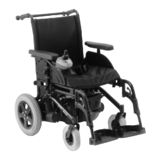
Key features 1) Push handle cross-strut 2) Locking screw for adjusting armrest height 3) Locking screw for adjusting backrest angle 4) Manual wheel lock (only right side visible in the picture) 5) Disengaging lever (not visible in the picture, located on both sides on each motor) 6) Remote 7) Legrest unlocking lever... -
Page 31: Getting In And Out Of The Wheelchair
Getting in and out of the wheelchair Important information when side transferring in and out of the wheelchair In order to side transfer it is necessary for the armrest to either be raised or removed completely depending on the model. A skirtguard can be installed as an option in connection with the parallel sliding armrest. -
Page 32: Remove The Standard Armrest In Order To Side Transfer
Remove the standard armrest in order to side transfer Removing the armrest: • Loosen star key screw (1) • Remove the side panel from the receptacle... -
Page 33: Swinging The Kerb Climber Rearward To Get In And Out Of The Powerchair
Swinging the kerb climber rearward to get in and out of the powerchair • Pull the handle (1) all the way forward. The kerb climber swings away towards the back and locks in place in this position. • To bring the kerb climber back towards the front, push the handle (1) rearward. - Page 34 Getting out of the wheelchair: • Drive your wheelchair as close as possible to your seat. • Switch your wheelchair off. • Apply the manual wheel lock of your wheelchair (if existing). • Detach the skirt guard of your wheelchair or swivel it up. •...
-
Page 35: Driving
Driving NOTE The maximum load capacity that is stated in the technical data only states that the system is designed for this mass in total. However, this does not mean that one can sit a person with this body weight in the wheelchair without restrictions. Attention must be paid to the body proportions, such as height, weight distribution, abdominal girth, leg and calf girth and seat depth. -
Page 36: Taking Obstacles
• The rear mirror (if installed) is adjusted so you can look behind at all times without having to bend forward or shift your seating position. Taking Obstacles 5.2.1 Maximum obstacle height You can find information about maximum obstacle heights in the chapter entitled "Technical specifications"... -
Page 37: The Correct Way To Overcome Obstacles
5.2.3 The correct way to overcome obstacles Information about the kerb climber! A kerb climber is a mechanism which enables the electric wheelchair to overcome obstacles which would normally not be possible due to their height. The way in which an obstacle should be approached (at right angles and slowly) is the same whether your wheelchair is fitted with a kerb climber or not. -
Page 38: Driving Up And Down Gradients
Driving up and down gradients For information concerning the maximum safe slope, please see chapter "Technical specifications" starting on page 109. WARNING: Danger of tipping over! • Only ever drive downhill at a maximum of 2/3 of the top speed. Avoid sudden changes of direction or abrupt braking when driving on slopes. -
Page 39: Parking And Stationary
Parking and stationary When parking your vehicle or if your vehicle is stationary for a prolonged period: • Switch the vehicle's power system off (ON-/OFF key). • Activate your anti-theft lock, if existing. 5.4.1 Activating and deactivating the manual wheel lock The manual wheel locks are located on the left and right sides above the wheels. -
Page 40: Use On Public Roads
If you wish to use your wheelchair on public roads and lighting is required by national legislation, then your wheelchair needs to be equipped with an appropriate lighting system. Please contact your Invacare ® dealer if you have any questions. Pushing the wheelchair in freewheel mode The motors of the wheelchair are equipped with automatic brakes, preventing that the wheelchair starts rolling out of control when the joystick box is switched off. -
Page 41: Remotes
Disengaging motors: • Switch off remote. • Rotate the engaging lever (1) to the side (position B). The motors are now disengaged. Re-engaging motors • Rotate the engaging lever (1) to the rear (position A). The motors are now re-engaged. Remotes Your wheelchair may be equipped with one of several different remotes. -
Page 42: Adjusting The Wheelchair To The User's Seating Posture
Adjusting the wheelchair to the user's seating posture Adjusting the armrests and the control panel 8.1.1 Adapting the control panel to the length of the user’s arm • Release wing nut (1) . • Adjust the remote by pushing it forwards or backwards to the required location. -
Page 43: Setting The Height Of The Remote
8.1.2 Setting the height of the remote • Release wing nut (1) . • Adjust remote to required height. • Retighten the wing nuts. -
Page 44: Setting The Height Of The Armrests
8.1.3 Setting the height of the armrests • Loosen the hand screw (1). • Adjust armrest to required height. • Retighten the hand nut. -
Page 45: Adjusting The Width Of The Armrests
8.1.4 Adjusting the width of the armrests The distance between the armrests can be adjusted by 4 cm on both sides (8 cm in total). WARNING! Danger of serious injury if an armrest falls out of it's fixation tube, due to it having been adjusted to a width that exceeds the specified value! •... - Page 47 Doing the adjustment • Loosen screw (1) • Adjust armrest to required position. • Retighten the screw. • Repeat this procedure for the second armrest.
-
Page 48: Adjusting The Backrest
Adjusting the backrest 8.2.1 Gas spring angle adjustment The levers (1) for adjusting the backrest are located on the push handles. The inclination can be infinitely adjusted within a range of + 3° and + 38°. Adjusting the backrest: • Pull both levers (1) upwards. •... -
Page 49: Manual Angle Adjustment
8.2.2 Manual angle adjustment The levers (1) for adjusting the backrest are located on the push handles. The inclination can be adjusted to four positions 3°, 13°, 23° and 33°. Adjusting the backrest: • Pull both levers (1) upwards. • Adjust backrest by moving the backrest forward or backwards. -
Page 50: Adjusting The Tension Adjustable Backrest Upholstery
8.2.3 Adjusting the tension adjustable backrest upholstery • Remove the backrest cushion (attached with Velcro strips) by pulling it up and off to access the adjustment straps. • Adjust the tension of the individual straps as desired. • Replace the backrest cushion. -
Page 51: Folding The Backrest Over
Folding the backrest over WARNING! Danger of most severe injury or death, if a wheelchair with a folding backrest is used as a vehicle seat! A wheelchair with a folding backrest does not fulfil the requirements of ISO 7176-19:2001. Using a wheelchair that does not fulfil these requirements as a vehicle seat can lead to the most severe injuries and even death in the event of a traffic accident. - Page 52 Folding the backrest over: • Pull both levers (1) upwards. • Fold the upper half of the backrest backwards. Folding the backrest up: • Fold the upper half of the backrest up. The hinges engage audibly.
-
Page 53: Postural Belts
Postural belts A postural belt is an option which can either be fixed to the wheelchair ex-works or can be retrofitted by your specialist dealer. If your wheelchair is fitted with a postural belt, your specialist dealer will have informed you about fitting and usage. The postural belt is used to help the wheelchair user keep an optimum sitting position. -
Page 54: Adjusting The Postural Belt Correctly
If the belt is only fastened with a bolted connection, ensure that the connection has not loosened or undone. You can find more information about maintenance work on belts in the service manual, which is available from Invacare®. -
Page 55: Headrest
• It is recommended to use a headrest during transport. The Invacare® headrest for this wheelchair (available as an option) is the perfect solution for use during transport. • The headrest must be adjusted to the ear height of the user. -
Page 56: Adjusting And Removing The Tray
Adjusting and removing the tray CAUTION: Injury hazard or material damage if a power wheelchair which is fitted with a table is transported in a vehicle! • If a table is fitted, always remove it before transporting the wheelchair. 8.6.1 Laterally adjusting the tray •... -
Page 57: Adjusting The Depth Of The Tray / Removing The Tray
8.6.2 Adjusting the depth of the tray / removing the tray • Loosen the wing-screw (1). • Adjust the table to the desired depth (or remove it entirely). • Re-tighten the screw. 8.6.3 Swinging the tray away to the side The tray can be swivelled up and away to the side to allow the user to get in and out of the mobility device CAUTION! Risk of injury! When the tray is raised it does not lock in place in this position! - Page 58 The tray can be swivelled upwards and pushed to the side as illustrated to enable getting on and off.
-
Page 59: Adjusting Footrests And Legrests
Adjusting footrests and legrests Standard legrests 9.1.1 Swivelling the footrest outward and/or removing The small release lever is to be found in the upper part of the legrest (1). When the legrest is released it can be swivelled inward or outward to facilitate access and also be removed completely. - Page 60 • Push the release lever inward or outward. The legrest is released. • Swivel the legrest inward or outward. • To remove the legrest simply pull upward.
-
Page 61: Adjusting The Length
9.1.1.1 Adjusting the length Pre-requisites: • 1x 5 mm hexagon socket spanner • Loosen the screw (1) using the Allen key, but do not remove completely. • Set the legrest to the desired length. • Re-tighten the screw. -
Page 62: Manually Height-Adjustable Legrest
Manually height-adjustable legrest 9.2.1 Swivelling the footrest outward and/or removing The unlocking knob is located on the top section of the legrests. When the legrest is unlocked, it can be swivelled to the inside or outside to facilitate getting in, or can be completely removed. •... -
Page 63: Adjusting The Angle
9.2.2 Adjusting the angle PLEASE NOTE: Danger of crushing! • Do not reach inside the swivelling range of the legrest! PLEASE NOTE: Danger of injury due to incorrect adjustment of the footrests and legrests. • Before and during every journey it is imperative to ensure that the legrests contact neither the castor wheels nor the ground! •... -
Page 64: Adjusting Legrest Length
9.2.3 Adjusting legrest length PLEASE NOTE: Danger of injury due to incorrect adjustment of the footrests and legrests. • Before and during every journey it is imperative to ensure that the legrests contact neither the castor wheels nor the ground! Pre-requisites: •... -
Page 65: Adjusting The Calf Support Depth
9.2.4 Adjusting the calf support depth The calf support has four depth settings. Pre-requisites: • 1x 4 mm Allen key • Swivel the calf support to the front. • Release bolt (1) with the Allen key and remove. • Set the nut on the other side to the required depth. •... -
Page 66: Adjusting The Calf Support Height
9.2.5 Adjusting the calf support height • Loosen the hand screw (1). • Adjust to required position. • Retighten the wing nuts. -
Page 67: Adjusting The Angle And Depth Adjustable Foot Plate
9.2.6 Adjusting the angle and depth adjustable foot plate Pre-requisites: • 1x 5 mm Allen key • Use the Allen key to loosen the set screw on the foot plate (1). • Adjust the foot plate to the desired angle or depth. •... -
Page 68: Electrical System
Electrical system 10.1 Electronics protection system The vehicle drive electronics is fitted with an overload protection. If the drive is severely overloaded over a long period (e.g. during steep climbs) and, above all, at simultaneous high external temperatures, the electronic system can overheat. In this case, the vehicle performance is gradually reduced until it comes to a standstill. -
Page 69: The Main Circuit Breakers
10.1.1 The main circuit breakers NOTE The circuit breakers are located on the left sides of the battery boxes. If the electrical system draws too much power for a period of time, one or both may overheat and pop out. To reactivate the electrical system, wait a few minutes until they have cooled down a bit, then push them back The illustration at right shows the positions of the circuit breakers (1) on the battery boxes. -
Page 70: Batteries
10.2 Batteries Power is supplied by two 12 V batteries. The batteries are maintenance-free and only need regular charging. In the following, you find information on how to charge, handle, transport, store, maintain, and use batteries. 10.2.1 Charging the batteries 10.2.1.1 General information on charging New batteries should always be fully charged once before their first use. -
Page 71: How To Charge The Batteries
10 °C. • Use only charging devices in Class 2. This class of chargers may be left unattended during charging. All charging devices which are supplied by Invacare® comply with these requirements. -
Page 72: How To Disconnect The Batteries After Charging
Risk of explosion and destruction of batteries if the wrong battery charger is used! • Only ever use the battery charger supplied with your vehicle, or a charger that has been approved by Invacare®. Risk of electric shock and damage to the battery charger if it gets wet! •... -
Page 73: Storage And Maintenance
10.2.2 Storage and Maintenance Follow the instructions listed below to ensure safe use and longevity of the batteries: • Always store the batteries fully charged. • Do not leave the batteries in a low state of charge for an extended length of time. Charge a discharged battery as soon as possible. - Page 74 The last 3 LED (two red and one orange) mean a remaining capacity of about 15 %. • Driving with blinking red LED’s means an extreme stress for the battery and should be avoided under normal circumstances. • When only one red LED is blinking, the Battery Safe feature is enabled. From this time, speed and acceleration is reduced drastically.
-
Page 75: Transporting Batteries
• Under normal operation, once a month the battery should be discharged until all green and orange LED are off. This should be done within one day. A 16 hour charge afterwards is necessary as reconditioning. 10.2.4 Transporting batteries The batteries supplied with your electric vehicle are not hazardous goods. This classification is based on the German GGVS Hazardous Goods Road Transport Ordinances, and the IATA/DGR Hazardous Goods Rail Transport / Air Transport Ordinances. - Page 76 • Only ever transport damaged batteries in an appropriate acid-resistant receptacle. • Wash all objects that have come into contact with acid with lots of water. Disposing of dead or damaged batteries correctly Dead or damaged batteries can be given back to your dealer or directly to Invacare®.
-
Page 77: Removing The Batteries
10.2.5.3 Removing the batteries CAUTION: Risk of fire and burns if battery poles are bridged! • When replacing the batteries the battery poles MUST NOT come into contact with metal parts of the wheelchair causing bridging. • Be sure to replace the battery pole caps after the batteries have been replaced. WARNING: Risk of fire and burns due to damage to the battery cables! •... - Page 78 • Open battery fixing strap (buckle). • Remove battery cable connecting plugs on both sides (the figure only shows the right-hand side).
- Page 79 • Pull the rear battery box out towards the back. • Open the battery retaining strap velcro fastening.
- Page 80 • Pull the battery retaining strap to the side over the edge of the battery box. • Open the battery box. • Pull the battery terminal caps (1) upwards and push them back to allow access to the battery terminals. •...
-
Page 81: Care And Maintenance
Care and maintenance NOTE: Have your vehicle checked once a year by an authorised Invacare® dealer in order to maintain it's driving safety and roadworthiness. Cleaning the vehicle When cleaning the vehicle, pay attention to the following points: • Only use a damp cloth and gentle detergent. - Page 82 Maintenance Jobs Seat and backrest padding: - Check for perfect condition. Side part and armrest: - Are all fastening elements installed? - Can armrests / side parts be removed and installed without too much physical effort? - Are armrests secured in their positions? Legrests: - Do legrests lock into place without any problem (only applies to detachable legrests)?
- Page 83 - Clean all parts carefully. When necessary Have your vehicle inspected and serviced once a year by your authorised dealer. A complete checklist of necessary maintenance work can be found in the Service Manual, which can be obtained from Invacare®.
-
Page 84: Maintenance- And Repair Work
"Technical specifications" on page 109, or consult the Service Manual, available from Invacare® (in this connection please see the addresses and phone numbers in section "How can you get in touch with Invacare®?" on page 3). In case you require assistance, please contact your Invacare® Dealer. -
Page 85: Repairing A Flat Tyre At The Back (Tyre Type 3.00-8")
12.1.1 Repairing a flat tyre at the back (tyre type 3.00-8") Injury hazard! If the wheel has been insufficiently secured during assembly, it can become loosened during driving! • When refitting the drive wheels, tighten the Torx screw that secures the wheel to the hub to a torque of 30 Nm! •... - Page 86 Removing the wheel • Jack the vehicle up and place a block of wood underneath it to prop it up. • Remove the countersunk screw (1) using the Torx bit. • Remove the wheel from the axle. EXPLOSION HAZARD! The wheel will explode if the air pressure is not released from the tyre before disassembling the wheel rim! •...
- Page 87 NOTE In case the old inner tube is to be repaired and used again, and it happens to get wet during repair, then it is easier to re-fit it if you powder it lightly with talcum powder. NOTE Re-assembly is done in reverse order. Make sure that the wheel is put back on the same side it was on, and that it runs in the same direction it did before it was removed.
-
Page 88: Transport
Transport CAUTION: Injury hazard or material damage if a power wheelchair which is fitted with a table is transported in a vehicle! • If a table is fitted, always remove it before transporting the wheelchair. CAUTION: Danger of death or serious injury to the mobility device user and potentially any other nearby occupant of the vehicle, if a mobility device is secured using a 4-point tie-down system available from a third party supplier and the unladen weight of the mobility device exceeds the maximum weight for which the tie-down system is certified! -
Page 89: Transferring The Wheelchair To A Vehicle
13.1 Transferring the wheelchair to a vehicle WARNING: The wheelchair is in danger of tipping over if it is transferred to a vehicle while the driver is still seated in the wheelchair! • Transfer the wheelchair without the driver whenever possible! •... -
Page 90: Securing The Wheelchair For Transport Without Passengers
CAUTION: Injury hazard! ® • If you are unable to fasten your electric wheelchair securely in a transport vehicle, Invacare recommends that you do not transport it! • Before transporting your wheelchair, make sure the motors are engaged and that the Joystick Box is switched off. -
Page 91: Use Of The Wheelchair As A Seat In A Vehicle
(UK for example), but may also be obtained from Invacare® as an option in other countries. This power wheelchair complies with the requirements of ISO 7176-19:2001 and may be used as a vehicle seat in connection with an anchoring system that has been checked and approved in accordance with ISO 10542. - Page 92 Caution: There is a danger of injury if the wheelchair is not properly secured during use as a vehicle seat! • If possible, the user should always leave the wheelchair to use a vehicle seat and the safety belts provided with the vehicle. •...
-
Page 93: How The Wheelchair Is Anchored In A Vehicle For Use As A Vehicle Seat
13.3.1 How the wheelchair is anchored in a vehicle for use as a vehicle seat The power wheelchair is fitted with four anchoring points, which are labelled with the symbol shown on the right. Snap hooks or belt loops can be used for fixation. -
Page 95: How The User Is Secured Within The Wheelchair
13.3.2 How the user is secured within the wheelchair CAUTION: There is a danger of injury if the user is not properly secured within the wheelchair! • Even if the wheelchair is fitted with a postural belt, this is no substitute for a proper safety belt which complies with ISO 10542 in the transport vehicle. - Page 96 • It is recommended to use a headrest during transport. The Invacare® headrest for this wheelchair (available as an option) is the perfect solution for use during transport. • The headrest must be adjusted to the ear height of the user.
- Page 97 Seat belts may not be held at a distance The pelvic belt should be positioned in the from the user's body using parts of the area between the user's pelvis and thighs wheelchair such as armrests or wheels. so that it is unobstructed and not too loose. The ideal angle of the pelvic belt to the horizontal is between 45°...
- Page 98 The safety belt installed in the transporting vehicle should be applied as shown in the illustration at right. 1) Centre line of the body 2) Centre of the sternum...
-
Page 99: Dismantling The Wheelchair For Transport
13.4 Dismantling the wheelchair for transport To dismantle and fold the wheelchair together for transport, please proceed as follows. • Remove legrests. • Remove the kerb climber (available as option and not always fitted). • Remove the battery cable. • Remove the battery case. •... -
Page 100: Removing Legrests
13.4.1 Removing legrests NOTE: Disassembly of the legrests is dependent on their type. For more information about this, please see Chapter Adjusting footrests and legrests on page 59. 13.4.2 Removing the kerb climber The kerb climber is fitted with quick release axles. The quick release axles are fitted with securing balls (1) which prevent the quick release axles sliding out of the mounting. - Page 101 Removing the kerb climber • Press the unlocking knobs and pull the quick release axles (1) out of the mountings. • Remove the kerb climber from the mountings.
-
Page 102: Removing Batteries
13.4.3 Removing batteries • Open battery fixing strap. • Remove battery cable connecting plugs on both sides (the figure only shows the right-hand side). - Page 103 • Pull the rear battery box out towards the back.
-
Page 104: Removing Backrest Frame Cross Strut
13.4.4 Removing backrest frame cross strut Removing the cross strut: • Release the knurled screws on both sides (1) of the cross strut. • Unhook the cross strut at the right-hand knurled screw. -
Page 105: Folding The Wheelchair
13.4.5 Folding the wheelchair Stage 1 Stage 2 Stage 3 Removing the seat cushion There are two locks (1) Press the locking lever (1) (1). located right and left under inwards and downwards. the seat which need to be opened in order to fold the chair together. - Page 106 Stage 4 Stage 5 Stage 6 Open the lock inwards. Tilt the wheelchair slightly to Repeat the procedure on the the side and press it other side. together.
-
Page 107: Reassembling The Wheelchair
• Cleaning and disinfection. Please see chapter "Care and maintenance" on page 81. • Inspection according to service plan. Please consult service instructions, available from Invacare®. • Adaptation to the user. Please see chapter "Adjusting the wheelchair to the user's seating... -
Page 108: Disposal
• Electric components and printed circuit boards are disposed of as electronic scrap. • Exhausted or damaged batteries can be returned to your medical equipment supplier or Invacare®. • Disposal must be carried out in accordance with the respective national legal provisions. -
Page 109: Technical Specifications
Technical specifications The technical information provided hereafter applies to a standard configuration or represents maximum achievable values. These can change if accessories are added. The precise changes to these values are detailed in the sections for the respective accessories. Permissible operating and storage conditions Temperature range for operation according to ISO 7176-9: •... - Page 110 Steering wheel tyres Tyre type • 200 x 50 mm pneumatic or solid rubber Tyre pressure The recommended maximum tyre pressure in bar or kpa is marked on the side wall of the tyre or the rim. If more than one value is listed, the lower one in the corresponding units applies.
- Page 111 Dimensions Seat depth • 400, 450, 500 mm Backrest height **** • 450, 530 mm Seat cushion thickness • 50 mm Backrest angle • +3° ... +35° (gas spring) • +14° (fixed) • 3°, 13°, 23°, 33° (manual) Armrest height (standard armrest) • 270 ... 340 mm Legrest length •...
- Page 112 **** Measured without seat cushion ***** The actual kerb weight depends on the fittings your mobility aid has been supplied with. Every Invacare® mobility aid is weighed when leaving the works. Please refer to the nameplate for the kerb weight (including batteries) measured.
-
Page 113: Inspections Performed
It is confirmed by stamp and signature that all jobs listed in the inspection schedule of the Service and Repair Instructions have been properly performed. The list of the inspection jobs to be performed can be found in the Service Manual which is available through Invacare®. Delivery Inspection...