Table of Contents
Advertisement
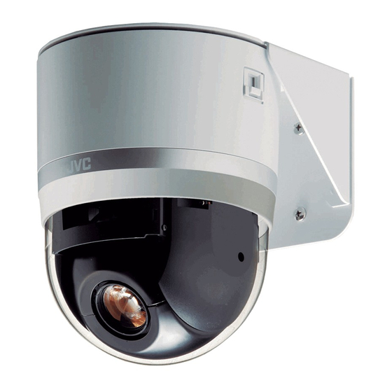
PTZ DOME CAMERA
OUTDOOR PTZ DOME CAMERA
TK-C685E
TK-C686E
TK-C685WPE
TK-C686WPE
Thank you for purchasing this product.
Before beginning to operate this unit, please read
the instruction manual carefully in order to make
sure that the best possible performance is obtained.
INSTRUCTIONS
TK-C685E/TK-C686E
TK-C686E (A)
TK-C686WPE (B)
TK-C685WPE/TK-C686WPE
LST0737-001B
Advertisement
Table of Contents

Related Manuals for JVC TK-C685E


Summary of Contents for JVC TK-C685E
- Page 1 PTZ DOME CAMERA OUTDOOR PTZ DOME CAMERA TK-C685E INSTRUCTIONS TK-C686E (A) TK-C686WPE (B) TK-C686E TK-C685WPE TK-C686WPE TK-C685E/TK-C686E TK-C685WPE/TK-C686WPE Thank you for purchasing this product. Before beginning to operate this unit, please read the instruction manual carefully in order to make sure that the best possible performance is obtained.
-
Page 2: Safety Precautions
[European Union] of the unit. This symbol indicates that the electrical and Mass: Approx. 1.9 kg (TK-C685E/TK-C686E) electronic equipment should not be disposed as general household waste at its end-of-life. Approx. 5.5 kg (TK-C685WPE/TK-C686WPE) Instead, the product should be handed over to the If the ceiling material (e.g., decorated plywood, plaster... -
Page 3: Getting Started
Contents of this manual does not have a slowdown mechanism, it is very durable, has a ● JVC holds the copyright to this manual. Any part or all of high stopping accuracy and can rotate smoothly even at low this manual may not be reproduced without prior speed. -
Page 4: Table Of Contents
Connection/Installation Others (TK-C685E/TK-C686E) Troubleshooting ............76 Camera Installation Procedures........14 Specifications ............... 77 Mounting the Camera ..........14 TK-C685E/TK-C686E ..........77 Switch Setting .............. 19 TK-C685WPE/TK-C686WPE ........78 Cable Connection ............22 Connection/Installation (TK-C685WPE/TK-C686WPE) Camera Installation Procedures........26 Mounting the Camera ..........26 Switch Setting .............. -
Page 5: Precautions
Otherwise, an error Maintenance and operating environment may occur during camera operation. TK-C685E/TK-C686E is an indoor camera. It cannot be A Face the heat release vents upward and secure the used outdoors. lens section with tape. -
Page 6: Getting Started
Handle the unit with care and do not subject it to vibration supply. The camera will be damaged. If the wrong cable is or shock. connected, the internal circuit will be damaged. Stop using the camera and send it to your nearest JVC dealer for repair. (Chargeable) - Page 7 ● The camera may be out of focus during zooming. Preset Positions You can configure up to a maximum of 256 preset positions on this product. The number of configurable preset positions varies according to the switch settings. A Page 19 [Switch Setting](TK-C685E/TK-C686E) A Page 30 [Switch Setting](TK-C685WPE/TK-C686WPE)
-
Page 8: Name And Function Of Parts
Getting Started Name and Function of Parts TK-C685E/TK-C686E Ceiling mount bracket Terminal Setting switch [ALARM I/O 2] Alarm Input 2 to 6/Alarm Output [CONTROL] Control signal connection terminal 2 Terminal (CN605) (J601) This is a terminal for alarm input 2 to 6 and alarm output 2. - Page 9 Camera Fixing holes (x3) Camera fixing lock knob (x2) This hole is for mounting the ceiling mount bracket to the This knob secures the camera to the ceiling so that it does ceiling or the ceiling recessed bracket (WB-S685U: Sold not fall.
-
Page 10: Tk-C685Wpe/Tk-C686Wpe
Getting Started Name and Function of Parts (continued) TK-C685WPE/TK-C686WPE Camera Camera securing hole (x4) Alarm Input 1/Alarm Output 1 Cable (5 cables) This hole is used for mounting the camera on the wall. Alarm Input 1, Alarm Output 1 Cable. (A Page 32) Cable connecting hole, cap Remove the cap and pull out the cables from this hole for... - Page 11 Camera (Interior) Alarm Input 2 to 6/Alarm Output 2 cable Option Switch This is a cable for alarm input 2 to 6 and alarm output 2. Configure this switch when Pelco protocol is used. (A Page 32) (A Page 19) Machine ID Setting Switch Cable color Signal Name...
-
Page 12: System Connection Example
(TK-C685WPE/TK-C686WPE) ● Do not connect the control signal cables in a loop. T TK-C685E/TK-C686E is used in the camera’s illustration. Note : ● Set the TERM switch of CAM1 to ON, and terminate at the controller with a resistance of 110 K. - Page 13 T TK-C685E/TK-C686E is used in the camera’s illustration.
-
Page 14: Connection/Installation (Tk-C685E/Tk-C686E)
Connection/Installation (TK-C685E/TK-C686E) Unfasten the ceiling mount bracket from the Camera Installation camera unit Procedures The ceiling mount bracket comes attached to the camera unit. Before installing, unfasten the ceiling mount bracket from the camera unit. A Check to ensure that the camera fixing lock knobs (x2) is not turned on. - Page 15 The camera will be damaged. If the wrong cable is connected, the internal circuit will be damaged. Stop CAUTION using the camera and send it to your nearest JVC dealer ● Take note of the length, strength, pull and material for repair. (Chargeable) (insulation) of the fall prevention wire and use one with ●...
- Page 16 Connection/Installation (TK-C685E/TK-C686E) Mount the terminal cover Mounting the Camera Return the terminal cover that was removed in step to its (continued) original position. The direction to pull out the cables changes according to the mounting method of the camera. Pulling out the cables from the side...
-
Page 17: Mounting The Camera To The Ceiling
Mounting the ceiling mount bracket to the Mounting the camera to the ceiling ceiling Remove the tape on the lens section Secure the ceiling mount bracket on the ceiling Remove the lens cap Install such that the DFRONT mark of the ceiling mount bracket faces the front. - Page 18 Connection/Installation (TK-C685E/TK-C686E) Note : Mounting the Camera ● Before mounting the camera, check that the camera fixing (continued) lock knobs are not locked (i.e., lock knobs are on top). The camera cannot be mounted if the lock knobs are locked.
-
Page 19: Switch Setting
Terminated and set the other cameras to Open . T1 : The settings of Switches 2, 4, and 5 are enabled only JVC Protocol when Switch 1 is turned OFF (JVC protocol). Pelco Protocol ● Preset Position Quantity Setting (Switch 2) Option Switch Configure this switch when Pelco protocol is used. - Page 20 D Topology Duplex Turn on the power of the camera ● The camera initializes and the following screen is displayed on the monitor. When JVC protocol is used >> << INITIAL PROCESS (100P) PAN : - - I - -...
- Page 21 Machine ID Set the machine ID using the combination of dip switch 1 to 8. (The factory default setting is OFF) Machine Machine ID setting Machine Machine ID setting Machine Machine ID setting Machine Machine ID setting switch switch switch switch 2 3 4 6 7 8...
-
Page 22: Cable Connection
Connection/Installation (TK-C685E/TK-C686E) Alarm Input 2 to 6/Alarm Output 2 Terminal Cable Connection Provided alarm cable Provided alarm Coaxial cable cable Power cable Alarm signal cable Control signal cable Connecting the alarm input/alarm output terminals Cable color Signal Name Alarm input 1/Alarm output 1 terminal... - Page 23 Alarm input terminal Connecting the coaxial cable Connects to sensors such as infrared sensors, door sensors, metal sensors and manual switches. Connecting a RG-59 coaxial cable. ● To prevent noise from entering the internal circuit, supply Treat the extremity of the coaxial cable as shown below non-voltage contact signal to the alarm input terminal.
- Page 24 Connection/Installation (TK-C685E/TK-C686E) Overall view of control signal cable connection Cable Connection RM-P2580 (continued) Camera terminal 1 TO CAMERA Terminal Camera terminal 2 Connecting the control signal cable The maximum connection distance with RM-P2580 is 1,200 Camera terminal 3 m. (Multiple cameras can be connected on one cable for RM- P2580 but the total length of the cable must be within 1,200 ●...
-
Page 25: Connecting The Power Cable
The camera will be damaged. If the wrong cable is connected, the internal circuit will be damaged. Stop using the camera and send it to your nearest JVC dealer for repair. (Chargeable) ● Turn on the power only after the connection for all the... -
Page 26: Connection/Installation (Tk-C685Wpe/Tk-C686Wpe)
Connection/Installation (TK-C685WPE/TK-C686WPE) Pull the cables from the hole in the wall Camera Installation Pull the power cable, BNC cable, control signal cable and Procedures alarm signal cable from the wall. Coaxial cable Install the camera with the following procedures. Power cable Preparation (A Page 26) Control signal cable Mounting the camera (A Page 28) - Page 27 A Use the screws (x4) to mount the dome cover to the camera. As a guide, install three claws of the dome cover and the central mark. Install such that the central mark appears above the JVC mark of the camera. Position aligning claws (x3) The central...
- Page 28 Connection/Installation (TK-C685WPE/TK-C686WPE) Camera Installation Cable Connection Procedures (continued) Connecting the coaxial cable (BNC) A Lower the protection cover and connect the connectors. B After connection is complete, cover the connectors with the protection cover. Mounting the Camera C Wind the waterproof tape (cohesive) from the top of Mount the fall prevention wire the protection cover.
- Page 29 Connecting the alarm cable and control signal Remove the dome cover protective sheet cable A Connect the cables. B After the connection is complete, wind the waterproof tape (cohesive). C Push the cables into the arm of the camera. Dome cover protective sheet Alarm Input 1/ Alarm Output 1...
-
Page 30: Switch Setting
Terminated and set the other cameras to Open . ● Multi Protocol (Switch 1) TT1:The settings of Switches 2, 4, and 5 are enabled only when Switch 1 is turned OFF (JVC protocol). JVC Protocol Pelco Protocol Option Switch ●... - Page 31 Turn on the power of the camera D Topology Duplex ● The camera initializes and the following screen is displayed on the monitor. When JVC protocol is used >> << INITIAL PROCESS (100P) PAN : - - I - -...
-
Page 32: Cable Connection
Connection/Installation (TK-C685WPE/TK-C686WPE) Memo : Cable Connection ● When alarm is switched ON/OFF, a sound will be produced from the alarm output 1 relay. If you do not want to hear the sound, use the alarm output 2 cable. However, be sure not to exceed the rating. - Page 33 ● If the wrong cable is connected, the internal circuit will be Solder welding or crimping damaged. Stop using the camera and send it to your nearest JVC dealer for repair. (Chargeable) ● Turn on the power only after the connection for all the devices is complete. Insulating...
-
Page 34: Changing Camera Settings From Remote Control
Changing camera settings from remote control Cursor Setting Procedures SETUP POSITION SETUP. . CAMERA. . CONTROL UNIT. . You can call out the camera menu and set functions from the remote control for systems that use the remote control unit. Memo : ●... -
Page 35: Menu Display When Using Pelco Protocol
● [ALARM INPUT] screen (A Page 42) Menu Display When Using Setting value changes ● [OFF, HOME, POS1 to POS99]B Pelco Protocol [OFF, POS1 to POS32, POS35 to POS82] ALARM INPUT ALARM INPUT When using this unit with Pelco protocol (A Page 19) INPUT1 INPUT1 INPUT2... -
Page 36: Flow Of Menu Screens
Changing camera settings from remote control Flow of Menu Screens RM-P2580 The menu screen consists of the following flow. (For details, see the reference page for each item) (A Page 38) Normal screen CAMERA FUNCTION1 V.PHASE POS. TITLE LOC. UP-L PRIVATE MASK.. - Page 37 (A Page 54) PRIVATE MASK MASK MODE MASK EDIT No 1 MODE MASK No.1 BRIGHT MASK No.2 MASK No.3 MASK No.4 MASK No.5 MASK No.6 MASK No.7 MASK No.8 < > < > < > MENU RETURN MENU RETURN EXECUTE <MENU>RETURN (A Page 56) MOTIOIN DETECT AREA EDIT...
-
Page 38: Language Setting
Changing camera settings from remote control LANGUAGE Setting (● indicates the default value) Item Setting value Functions and settings ● ENGLISH LANGUAGE For selecting the menu’s display language. FRENCH GERMAN SPANISH ITALIAN CAMERA FUNCTION1 screen (● indicates the default value) Item Setting value Functions and settings... - Page 39 Item Setting value Functions and settings ● OFF HOME M.DETECT When the camera is at home position, this item sets the Motion Detect function, which activates when there is a movement in the video. ALARM The alarm signal will be output from the alarm output terminal. TRACKING Note : ●...
-
Page 40: Camera Function2 Screen
Changing camera settings from remote control CAMERA FUNCTION1 screen (continued) (● indicates the default value) Item Setting value Functions and settings D.ZOOM MAX When the zoom lens is set to telephoto, optical zoom and electronic zoom will be ● enabled. This item sets the maximum value of the electronic zoom function. Memo : ●... - Page 41 Item Setting value Functions and settings VAR.P/T SPEED This item changes the operation speed of pan (horizontal rotation) and tilt (vertical ● ON rotation) automatically according to the zoom of the lens. When the zoom lens is at TELE (telephoto), the pan and tilt speed is slow. When it is at WIDE (wide angle), the pan and tilt speed is fast.
-
Page 42: Camera Title/Alarm Screen
Changing camera settings from remote control CAMERA TITLE/ALARM screen This screen allows you to configure title and alarm settings. (● indicates the default value) Item Setting value Functions and settings CAM.TITLE EDIT.. This item sets the title to be displayed permanently on the lower left of the screen. - Page 43 AUX1, AUX2, AUX3 : Alarm signals are output when there is an auxiliary input. Memo : ● In normal cases, do not use AUX1 , AUX2 , AUX3 . For details, please consult your nearest JVC dealer.
-
Page 44: Camera Alc Screen
Changing camera settings from remote control CAMERA ALC screen This function performs automatic adjustment according to the brightness. It sets the video signals of the camera such as color level and contour enhancement. (● indicates the default value) Item Setting value Functions and settings ●... - Page 45 Item Setting value Functions and settings B&W/COLOUR This item sets the mode switching of B&W and Color. MODE.. Memo : ● When switching the Color mode to B&W mode, the type of light source may cause the focus to be dislocated. This is because the B&W mode is sensitive to both visible light and near-infrared light.
-
Page 46: Camera Video Screen
Changing camera settings from remote control CAMERA VIDEO screen (● indicates the default value) Item Setting value Functions and settings ● CRT MONITOR TYPE This sets the monitor type. LCD1 You can change the output video settings according to the type of monitor used. LCD2 Select an appropriate mode. -
Page 47: Auto Pan/Patrol/Trace Screen
AUTO PAN/PATROL/TRACE screen This screen sets the Auto Pan function that rotates slowly in a horizontal direction, the Auto Patrol function that moves the camera to multiple positions in sequence, and the Auto Trace function that reproduces manual camera settings. (●... - Page 48 Changing camera settings from remote control AUTO PAN/PATROL/TRACE screen (continued) (● indicates the default value) Item Setting value Functions and settings AUTO PAN/TRACE This item sets the images during Auto Pan and Auto Trace. VIDEO IRIS MODE MANUAL This item sets the adjustment method for lens iris. ●...
- Page 49 Item Setting value Functions and settings AUTO PAN/TRACE VIDEO (continued) ● ATW-W W.BALANCE This item sets the white balance adjustment function. You can adjust the illumination within the color temperature range of 2,300K to 10,000K. ATW-N ATW-N : This is the Auto-Tracking White Balance mode. (Automatic color temperature tracking).
-
Page 50: Pos.function Set
Changing camera settings from remote control POS.FUNCTION SET.. screen (● indicates the default value) When preset position is set to 100 (A Page 19)(A Page 30) Item Setting value Functions and settings POSITION TITLE.. This item sets a title of maximum 16 characters for the configured positions (99) and home position (1), and displays the title on the screen. - Page 51 Item Setting value Functions and settings ● ATW-W W.BALANCE This item sets the white balance adjustment function. You can adjust the illumination within the color temperature range of 2,300K to 10,000K. ATW-N ATW-N : This is the Auto-Tracking White Balance mode. (Automatic color temperature tracking).
- Page 52 Changing camera settings from remote control POS.FUNCTION SET.. screen (continued) (● indicates the default value) Item Setting value Functions and settings POSITION VIDEO (continued) ExDR LEVEL –5 to NORMAL to 5 This item sets which brightness area of the object is to be more visible during ExDR mode.
-
Page 53: Factory Settings Screen
FACTORY SETTINGS screen Setting reverts back to default setting. When the [SET] button is pressed, FACTORY SETTINGS... will be displayed for about 20 seconds. Then settings will revert back to default settings. After this is complete, DATA CLEARD will be displayed. (●... -
Page 54: Detailed Setting
Detailed setting Mask Setting Private Mask Setting Open the [MASK MODE] screen ● Shift the [PAN/TILT] lever to the left and right and set [MODE] to ON . ● Press the [SET] button to display the [MASK MODE] This function allows you to configure settings to mask the screen. - Page 55 Press the [SET] button Level Setting ● The [MASK EDIT] screen is displayed. (A frame Select [BRIGHT] at the [PRIVATE MASK] screen appears at the mask area) ● Move the cursor ( ) to the [BRIGHT] item, shift the [PAN/TILT] lever to the left and right and set the MASK EDIT No1 BRIGHT (mask color).
-
Page 56: Home Motion Detect (Alarm) Setting
Detailed setting Preparation Home Motion Detect Select a camera (A RM-P2580 Instruction Manual) (Alarm) Setting [CAMERA] button B Numeric keypad (camera number) B [ENTER] button ● Images from the selected camera are output. Display the [MENU] screen (A Page 34) When the camera is at the home position, the Motion Detect function will activate when there is a movement in the ●... - Page 57 Setting Note : ● The Motion Detect feature is not designed to prevent Setting non-detection area thefts or fire disasters. Our company shall not be liable for ● Select [AREA EDIT..] and press the [SET] button. any inconveniences or damages that occur. ●...
-
Page 58: Home M.detect (Tracking) Setting
Detailed setting Preparation HOME M.DETECT Select a camera (A RM-P2580 Instruction Manual) (TRACKING) Setting [CAMERA] button B Numeric keypad (camera number) B [ENTER] button ● Images from the selected camera are output. Display the [MENU] screen (A Page 34) This item sets the function to automatically track objects with movement when the camera is at the home position. - Page 59 Setting Note : ● The Motion Detect feature is not designed to prevent Set [LEVEL] thefts or fire disasters. Our company shall not be liable for ● Move the cursor ( ) to the [LEVEL] item, shift the any inconveniences or damages that occur. [PAN/TILT] lever to the left and right and set the ●...
-
Page 60: Manual Pan Limit Setting
Detailed setting Preparation Manual Pan Limit Setting Select a camera (A RM-P2580 Instruction Manual) ● [CAMERA] button B Numeric keypad (camera number) B [ENTER] button ● Images from the selected camera are output. This feature sets the panning (horizontal) area during Display the [MENU] screen (A Page 34) manual operation. - Page 61 Setting Basic Operation of Manual Pan Limit ● When manual pan limit is set, panning is only available in Set the left limit position the effective area. ● Use the [PAN/TILT] lever (left/right) to determine the left ● This operation has priority over manual pan limit. When limit position.
-
Page 62: Camera Title Setting
Detailed setting Setting Camera Title Setting Check that the cursor ( ) is at [CAM.TITLE EDIT..] and press the [SET] button ● The [CAM.TITLE EDIT] screen is displayed. ● The first character from the character area flashes on A maximum of 16 characters can be set for the title. and off and is ready for input. -
Page 63: Area Display Mode Setting (Title)
Setting Area Display Mode Setting Move the cursor ( ) to [AREA DISPLAY], shift the (Title) [PAN/TILT] lever to the left and right to select TITLE , and press the [SET] button ● The [AREA TITLE EDET AREA1] screen is displayed. (The home position corresponds to area No. -
Page 64: Area Display Mode Setting (Direction)
Detailed setting Area Display Mode Setting MENU (Direction) LANGUAGE ENGLISH CAMERA FUNCTION1.. CAMERA FUNCTION2.. CAMERA TITLE/ALARM.. CAMERA ALC.. CAMERA VIDEO.. AUTO PAN/PATROL/TRACE.. When the basic axis direction N (north) is set, this function POS.FUNCTION SET.. divides the 360 panning (horizontal rotation) area into 8 FACTORY SETTINGS.. -
Page 65: Remote Control Alarm Title Setting
Setting Remote Control Alarm Title Move cursor ( ) to [ALARM TITLE EDIT..] and press Setting the [SET] button ● The [ALARM TITLE EDIT No.1] screen is displayed. ● The first character from the character area flashes on and off and is ready for input. This item sets the title to be displayed during alarm input. -
Page 66: Auto Pan Setting
Detailed setting Auto Pan setting [MENU] button [SET] button This item sets the auto pan operation. Auto pan refers to the Numeric keypad following operations. ● Slow movement between two preset points (you can [CAMERA] button set any two points that are connected horizontally, vertically, or diagonally) [PAN/TILT] Lever ●... - Page 67 Setting Press the [SET] button (only during RETURN ) The start position switches to the end position. Select [AUTO PAN SET..] and press the [SET] button ● Check that the cursor is at [AUTO PAN SET..] and AUTO PAN POSITION SET AUTO PAN POSITION SET press the [SET] button ●...
-
Page 68: Auto Patrol Setting
Detailed setting Preparation Auto Patrol Setting Select a camera (A RM-P2580 Instruction Manual) ● [CAMERA] button B Numeric keypad (camera number) B [ENTER] button ● Images from the selected camera are output. This item sets the Auto Patrol function where the camera Display the [MENU] screen (A Page 34) moves to multiple positions in order. - Page 69 Setting To operate Auto Patrol: Shift up and down the [PAN/TILT] lever and move the ● To operate Auto Patrol in the camera, press the [AUTO cursor ( ) to a patrol number you wish to set PATROL] button of RM-P2580. ●...
-
Page 70: Auto Trace Setting
Detailed setting Preparation Auto Trace Setting Select a camera (A RM-P2580 Instruction Manual) ● [CAMERA] button B Numeric keypad (camera number) B [ENTER] button ● Images from the selected camera are output. This item sets the Auto Trace function (approx. 30 seconds) Display the [MENU] screen (A Page 34) that reproduces manual camera settings. - Page 71 Setting To operate Auto Trace: Set start position ● To perform Auto Trace on the camera, [RM.A.PAN KEY] ● Use the [PAN/TILT] lever and [FOCUS (NEAR) (FAR)], (A Page 49) item of the [AUTO PAN/PATROL/TRACE] [ZOOM(WIDE) (TELE)] buttons to set the start screen must be set to A.TRACE .
-
Page 72: Position Title Setting
Detailed setting Preparation Position Title Setting Select a camera (A RM-P2580 Instruction Manual) ● [CAMERA] button B Numeric keypad (camera number) B [ENTER] button ● Images from the selected camera are output. This item sets the title to be displayed when selecting Display the [MENU] screen (A Page 34) positions. - Page 73 Setting Check that the cursor ( ) is at the [POSITION TITLE..] item and press the [SET] button ● The Edit Position Title screen appears. ● The first character from the character area flashes on and off and is ready for input. Select a position (A RM-P2580 Instruction Manual) [POSITION] button B Numeric keypad (position number) B [ENTER] button...
-
Page 74: Auto White Balance Setting
Detailed setting Preparation Auto White Balance Setting Select a camera (A RM-P2580 Instruction Manual) ● [CAMERA] button B Numeric keypad (camera number) B [ENTER] button ● Images from the selected camera are output. Each light source has its own color temperature. Therefore, Display the [MENU] screen (A Page 34) when the main light source lighting an object is changed, set the [W.BALANCE] item to AWC and adjust the white... - Page 75 Setting Place a white object at the center of the screen, under the same lighting condition as the object to be shot and zoom in to fill the screen with white. Set [W.BALANCE] to AWC ● Shift up and down the [PAN/TILT] lever and move the cursor ( ) to the [W.BALANCE] item.
-
Page 76: Others
● The built-in cooling fan or heater fan ● Take down the characters displayed on FAN STOP T T , and appears on the screen. (TK-C685WPE/TK-C686WPE only) is malfunctioning. (T T are numeric consult your nearby JVC dealer. characters) Turn off the power of this unit. -
Page 77: Specifications
: 360 endless rotation Horizontal rotation speed : Approximately 0.04 /s to approximately 500 /s Vertical rotation range : -5 to 185 (Horizontal to lower to Horizontal) TK-C685E/TK-C686E Vertical rotation speed : Approximately 0.04 /s to approximately 500 /s CAMERA HEAD Overall... -
Page 78: Tk-C685Wpe/Tk-C686Wpe
CAMERA HEAD Image pickup device : 1/4 type, Interline Transfer CCD Effect pixels : 752 (H) x 582 (V) Synchronization system TK-C685E/TK-C686E (continued) : Internal synchronization/Linelock : VBS 1 V(p-p) 75 K Video output Ceiling mounting hole [Unit: mm (inch)] Scanning frequency : Horizontal 15.625 kHz, Vertical 50 Hz... - Page 79 Rotation platform Wall mounting hole [Unit: mm (inch)] Horizontal rotation range : 360 endless rotation 152(5 63/64 Horizontal rotation speed 126(4 31/32 : Approximately 0.04 /s to approximately 500 /s 31/64 Vertical rotation range : -5 to 185 (Horizontal to lower to Horizontal) Vertical rotation speed : Approximately 0.04 /s to...
- Page 80 © 2008 Victor Company of Japan, Limited LST0737-001B...