
Related Manuals for JVC LWT0254-001B-H


Summary of Contents for JVC LWT0254-001B-H
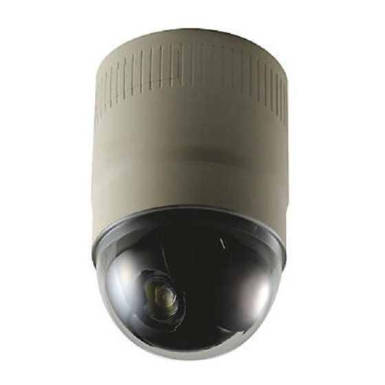
- Page 1 DOME TYPE CAMERA TK-C625 For Customer Use: Enter below the Model No. and Serial No. which is located on the body. Retain this information for future reference. Model No. TK-C625 Serial No. INSTRUCTIONS LWT0254-001B-H...
-
Page 2: Safety Precautions
●Consult the dealer or an experienced radio/TV technician for help. CAUTION CHANGES OR MODIFICATIONS NOT APPROVED BY JVC COULD VOID USER’S AUTHORITY TO OPERATE THE EQUIPMENT. THIS DEVICE COMPLIES WITH PART 15 OF THE FCC RULES. -
Page 3: Important Safeguards
IMPORTANT SAFEGUARDS These are general IMPORTANT SAFEGUARDS and certain items may not apply to all appliances. IMPORTANT SAFEGUARDS 1. Read all of these instructions. 2. Save these instructions for later use. 3. All warnings on the product and in the operating instructions should be adhered to. 4. -
Page 4: Table Of Contents
Introduction Thank you for purchsing this product. (These instructions are for TK-C625U/TK-C625E) TK-C625U : For North American Market. TK-C625E : For European Market. “TK-C625” is used for common descriptions between both models in this manual. Before beginning to operate this unit, please read the instruction manual carefully in order to make sure that the best possible performance is obtained. -
Page 5: Operating Precautions
Introduction (continued) Operating Precautions WARNING ●Install the unit on a strong and stable surface. This unit has been designed to revolve at high speed. Due to its weight (about 1.3 kg) and the vibrations it may be subjected to, the camera must be mounted to a sturdy and stable material. - Page 6 Introduction (continued) Operating Precautions (continued) ●If a very bright object (such as a lamp) is being monitored, the picture may contain vertical lines (smear) above and below the bright object in the picture. This is a phenomenon normal to a solid-state image pickup device (CCD) and is not a malfunction.
-
Page 7: Name And Function Of Parts
Introduction (continued) Name and Function of Parts Ceiling Mount (Terminal Side) Safety Wire Hang this wire to the Fastening Hook for Safety Wire [VIDEO OUT] Coaxial Cable Terminal Output terminal of a composite video signal (1 V(p-p)) with an output impedance of 75 K, to be connected to a switcher, etc. - Page 8 Introduction (continued) Name and Function of Parts (continued) Ceiling Mount (Setting Switch Side) Clamping Hole (x 4) Use these holes to attach the camera to the ceiling or ceiling recessed bracket (WB-S625: sold separately). Camera Connection Terminal (Female) Connect this to the Camera Connection Terminal (Male) on the camera.
-
Page 9: Connections & Installation
Connections & Installation Multi-Drop Communication System A system that employs the RM-P2580 as the controller. The following figure shows a system that can accommodate up to eight cameras. (100 positions can be preset per camera.) Camera 1 Control signal cable Coaxial cable TK-C625 MACHINE ID: 01... - Page 10 Connections & Installation (continued) Multi-Drop Communication System (continued) A system that does not employ the RM-P2580 as the controller. ● Be sure to terminate the control signal cable at both ends. The cables (length of stub) connecting pieces of non-terminated equipment (cameras or controllers) must be as short as possible.
-
Page 11: Point-To-Point Communication System
Connections & Installation (continued) Point-to-Point Communication System The following illustration shows a system in which a remote control unit (or a similar piece of equipment) controls a single camera. Video out Control signal cable Switch 4 : OFF (Point to Point) Switch 8 : ON (Terminated 110 K) Observe the following points when connecting components together:... - Page 12 Connections & Installation (continued) Point-to-Point Communication System (continued) Use twisted-pair cables for the connections. ●Duplex When the camera is controlled using the full duplex protocol, set the Switch 5 of the Setting switch to ON. Camera RX + RX - TX + TX - Four wires must be connected.
-
Page 13: Switch Settings
Connections & Installation (continued) Switch Settings Set the switches on the Ceiling Mount before installing the camera. Settings vary according to configuration of the system used. Setting switches Setting not required. Set all to OFF. R RESERVED (Switches 1, 2, 3) These switches must be set to OFF. - Page 14 Connections & Installation (continued) Switch Settings (continued) Machine ID Setting Switch When controlling the system using a multi-drop remote control unit such as RM-P2580, for instance, assign a number (machine ID) for identification to each of the connected cameras. Assign a machine ID according to the video input number of RM-P2580.
- Page 15 Connections & Installation (continued) Machine ID Set the Machine ID using a combination of numbers between 1 to 8. (This is set to OFF in the factory settings.) Machine ID Installation Machine ID Installation Switch Switch Machine ID Installation Switch Machine ID Installation Switch...
-
Page 16: Cable Connections
Connections & Installation (continued) Cable Connections CAUTIONS ●Ensure to attach the cover for the ceiling mount. Installation is not possible without attaching the cover. ●The cover prevents penetration of foreign objects into the ceiling mount. Penetration of foreign objects may cause a malfunction or, in the worst scenario, cause smoking or fire. -
Page 17: Connection Of Coaxial Cables
Connections & Installation (continued) Connection of Alarm Input / Output Terminals Connect the alarm input/output terminals to external devices such as sensors and buzzers. Follow the diagram below to loosen and remove the screws on the two edges of the terminal block. Strip the coating of the alarm signal cable by about 4 mm before inserting it into the terminal. - Page 18 ● The internal circuit may be damaged if the cable is connected by mistake. In this case, ensure that you stop using and contact the nearest JVC dealers. Control Signal Cables Connect to AC 24 V power supply.
-
Page 19: Installing The Ceiling Mount
● Please refer to the instruction manual of the cover in use for details on installation of the recessed cover (recess bracket). ● For more detail, please contact the JVC dealers. Embedded Cover Ceiling (recess bracket) Attach the Safety Wire Connect the ceiling slab or channel to the ceiling mount using a safety wire to prevent the camera from falling down. -
Page 20: Installing The Camera
Connections & Installation (continued) Installing the Camera Attach the Safety Wire Follow the diagram to pull out the Safety Wire from the ceiling mount, followed by hanging it to the Fastening Hook for Safety Wire on the camera. Safety Wire Fastening Hook for Safety Wire CAUTION... -
Page 21: Setting Up The Camera Using Rm-P2580
Setting Up the Camera Using RM-P2580 Setup Procedure MENU button Power switch SET button (Rear panel) POWER lamp REMOTE CONTROL UNIT RM-P2580 CAMERA POSITION SETUP POWER ALARM MENU AUTO KEY LOCK LENS CAMERA/POSITION PAN/TILT CAMERA POSI- SPEED TION CLOSE IRIS OPEN OPTION OPTION... -
Page 22: Menu Screen Configuration
Setting Up the Camera Using RM-P2580 (continued) Menu Screen Configuration Press the MENU button for 1 second SETUP POSITION SETUP. . CAMERA. . CONTROL UNIT. . *1: Only applicable to the TK-C625E model. For TK-C625U, this is displayed as COLOR . *2: Only displayed for the TK-C625E model. - Page 23 Setting Up the Camera Using RM-P2580 (continued) A pg. 31 PRIVATE MASK MODE MASK No. 1 ( - ) MASK EDIT .. MASK DELETE .. < > MENU RETURN A pg. 32 M. PAN LIMIT POS.SET [ L ]POS.SETTING → <...
-
Page 24: Camera Function 1 Screen
Setting Up the Camera Using RM-P2580 (continued) CAMERA FUNCTION 1 Screen Item V. PHASE This adjusts the vertical synchronization to those of other cameras when a selector switch for the synchronizing system on the Ceilling Mount is at LL. (50 Hz *(60Hz) power region only.) *( ) : TK-C625U Set values : TK-C625E : -156 to 0 to 156 TK-C625U : -131 to 0 to 131... - Page 25 Setting Up the Camera Using RM-P2580 (continued) Item AF FOR IR When in the B&W mode, this camera is sensitive to both visible and near-IR lights. As such, images may become out of focus upon switching from the Color to B&W mode, depending on the type of light source used.
-
Page 26: Camera Title/Alarm Screen
Setting Up the Camera Using RM-P2580 (continued) CAMERA TITLE/ALARM Screen Item CAM. TITLE EDIT.. Use this to specify the title that is always displayed at the bottom left of the screen. Specify up to a maximum of 16 characters. CAMERA TITLE Setup (A pg. 34) AREA DISPLAY Use this to perform area setting. -
Page 27: Camera Alc/Video Screen
Setting Up the Camera Using RM-P2580 (continued) CAMERA ALC/VIDEO Screen This screen enables automatic adjustment according to the brightness. Setting can be performed for the camera video signals, such as color level and contour enhancement. Item SHUTTER Sets the speed of the electronic shutter. Set Values TK-C625E : 1/50, 1/120, 1/250, 1/500, 1/1000, 1/2000, 1/4000, 1/10000 TK-C625U : 1/60, 1/100, 1/250, 1/500, 1/1000, 1/2000, 1/4000, 1/10000... -
Page 28: Auto Pan/Patrol/Trace Screen
Setting Up the Camera Using RM-P2580 (continued) CAMERA ALC/VIDEO Screen (continued) Item COLOUR LEVEL Adjusts the color level of video signals. (TK-C625E) To decrease…………… Set a smaller value. COLOR LEVEL To increase……………. Set a larger value. (TK-C625U) [Set values: -5 to NORMAL to 5] ENHANCE LEVEL Sets the contour enhancement which controls the sharpness on the monitor screen. -
Page 29: Pos. Function Set Screen
Setting Up the Camera Using RM-P2580 (continued) Item AUTO PAN TRACE/ For setting video images during Auto Pan and Auto Trace. VIDEO.. IRIS MODE For setting the method of lens iris adjustment. AUTO : Adjusts iris automatically to the default state. AUTO+ : Adjusts iris automatically to a level brighter than the default state. -
Page 30: Factory Settings Screen
Setting Up the Camera Using RM-P2580 (continued) POS. FUNCTION SET Screen (continued) Item AVERAGE : PEAK For setting the method of exposure detection according to the ratio between the average and peak values. ●Larger AVERAGE Value : Use this setting when areas other than those highlighted are ●Larger PEAK Value [Set values: 10:0, 9:1, 8:2, 7:3, 6:4, 5:5] BLC MODE... -
Page 31: Private Mask Setup
Setting Up the Camera Using RM-P2580 (continued) PRIVATE MASK Setup MENU button SET button PAN lever CAMERA button REMOTE CONTROL UNIT CAMERA POSITION SETUP POWER ALARM MENU AUTO KEY LOCK LENS CAMERA/POSITION PAN/TILT CAMERA POSI- SPEED TION IRIS OPTION OPTION CLOSE OPEN FOCUS... -
Page 32: Manual Pan Limit Setup
Setting Up the Camera Using RM-P2580 (continued) MANUAL PAN LIMIT Setup MENU button SET button PAN lever CAMERA button REMOTE CONTROL UNIT CAMERA POSITION SETUP POWER ALARM MENU AUTO KEY LOCK LENS CAMERA/POSITION PAN/TILT CAMERA POSI- SPEED TION IRIS OPTION OPTION CLOSE OPEN... - Page 33 Setting Up the Camera Using RM-P2580 (continued) MANUAL PAN LIMIT Setup (continued) Right Limit Invalid Range Left Limit Basic operation of Manual Pan Limit ●Panning operation will only be allowed within the valid range upon setting the Manual Pan Limit. ●When the camera is moved by an operation that overrides the Manual Pan Limit into a region outside the valid panning range, the camera will function as follows when a manual Pan operation is performed.
-
Page 34: Camera Title Setup
Setting Up the Camera Using RM-P2580 (continued) CAMERA TITLE Setup MENU button SET button PAN lever CAMERA button REMOTE CONTROL UNIT CAMERA POSITION SETUP POWER ALARM MENU AUTO KEY LOCK LENS CAMERA/POSITION PAN/TILT CAMERA POSI- SPEED TION IRIS OPTION OPTION CLOSE OPEN FOCUS... -
Page 35: Area Display Setup (Title)
Setting Up the Camera Using RM-P2580 (continued) AREA DISPLAY Setup (TITLE) MENU button SET button PAN lever CAMERA button REMOTE CONTROL UNIT RM-P2580 CAMERA POSITION SETUP POWER ALARM MENU AUTO KEY LOCK LENS CAMERA/POSITION PAN/TILT CAMERA POSI- SPEED TION IRIS CLOSE OPEN OPTION... -
Page 36: Area Display Setup (Direction)
Setting Up the Camera Using RM-P2580 (continued) AREA DISPLAY Setup (DIRECTION) East MENU button SET button PAN lever CAMERA button REMOTE CONTROL UNIT CAMERA POSITION SETUP POWER ALARM MENU AUTO KEY LOCK LENS CAMERA/POSITION PAN/TILT CAMERA POSI- SPEED TION IRIS CLOSE OPEN OPTION... -
Page 37: Alarm Title Setup
Setting Up the Camera Using RM-P2580 (continued) ALARM TITLE Setup MENU button SET button PAN lever CAMERA button REMOTE CONTROL UNIT RM-P2580 CAMERA POSITION SETUP POWER ALARM MENU AUTO KEY LOCK LENS CAMERA/POSITION PAN/TILT CAMERA POSI- SPEED TION IRIS OPTION OPTION CLOSE OPEN... -
Page 38: Auto Pan Setup
Setting Up the Camera Using RM-P2580 (continued) AUTO PAN Setup Gradual Rotation MENU button SET button PAN lever CAMERA button REMOTE CONTROL UNIT RM-P2580 CAMERA POSITION SETUP POWER ALARM MENU AUTO KEY LOCK LENS CAMERA/POSITION PAN/TILT CAMERA POSI- SPEED TION CLOSE IRIS OPEN... -
Page 39: Auto Patrol Setup
Setting Up the Camera Using RM-P2580 (continued) AUTO PATROL Setup High speed High speed High speed High speed MENU button POSITION button SET button PAN lever CAMERA button REMOTE CONTROL UNIT RM-P2580 CAMERA POSITION SETUP POWER ALARM MENU AUTO KEY LOCK LENS CAMERA/POSITION PAN/TILT... -
Page 40: Auto Trace Setup
Setting Up the Camera Using RM-P2580 (continued) AUTO TRACE Setup MENU button AUTO PAN button SET button PAN lever CAMERA button REMOTE CONTROL UNIT CAMERA POSITION SETUP POWER ALARM MENU AUTO KEY LOCK LENS CAMERA/POSITION PAN/TILT CAMERA POSI- SPEED TION IRIS OPTION OPTION... -
Page 41: Position Title Setup
Setting Up the Camera Using RM-P2580 (continued) POSITION TITLE Setup MENU button POSITION button SET button PAN lever CAMERA button REMOTE CONTROL UNIT CAMERA POSITION SETUP POWER ALARM MENU AUTO KEY LOCK LENS CAMERA/POSITION PAN/TILT CAMERA POSI- SPEED TION IRIS OPTION OPTION CLOSE... -
Page 42: Other
Other Troubleshooting Symptom Picture is not displayed. Is there a problem in the power cable(s) connecting the camera to the power supply unit? (If the power cable(s) are too long or of an inadequate size, the correct voltage may not be supplied due to an increase in cable resistance.) Power cannot be turned Are cables connected properly to the terminal board on... -
Page 43: Specifications
Other (continued) Specifications Camera Image pickup device:1/4 type, interline transfer CCD TK-C625E: 752 (H) x 582 (V) pixels TK-C625U: 768 (H) x 494 (V) pixels Sync system : Internal, Line Lock : VBS 1V (p-p) 75 K Video output Scanning frequencies : TK-C625E: 15.625 (H), 50 Hz (V) TK-C625U: 15.734 (H), 59.94 Hz (V) : 50 dB (typical) (AGC mode: OFF, Enhance level: -5) - Page 44 Printed in Thailand © 2005 Victor Company of Japan, Limited LWT0254-001B-H...