Dell POWEREDGE T410 Technical Manualbook
Hide thumbs
Also See for POWEREDGE T410:
- Hardware owner's manual (204 pages) ,
- Getting started with (63 pages) ,
- Technical manual (57 pages)

Related Manuals for Dell POWEREDGE T410


Summary of Contents for Dell POWEREDGE T410
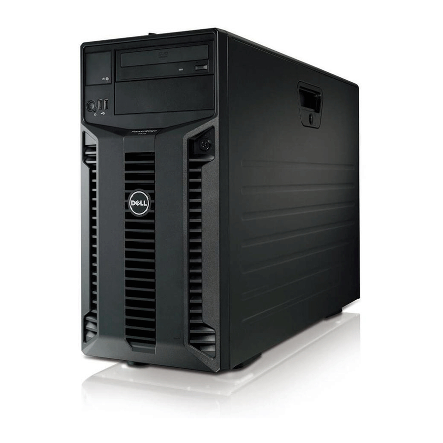
- Page 1 PowerEdge T410 Technical Guidebook DELL POWEREDGE T410 TECHNICAL GUIDEBOOK INSIDE THE POWEREDGE T410 Dell...
-
Page 2: Table Of Contents
PowerEdge T410 Technical Guidebook Table of Contents Product Comparison........................1 Overview/Description ......................1 New Technologies ........................3 New Technologies Used in the PowerEdge T410 ..............3 System Overview ........................3 Overview/Description ......................3 Product Features Summary ....................4 Mechanical ..........................7 Chassis Description ...................... - Page 3 PowerEdge T410 Technical Guidebook Supported Processors ......................31 Processor Configurations ....................32 Processor Installation ......................33 Overview/Description ......................33 DIMM Types Supported ..................... 33 Slots/Risers ........................33 Mirroring ..........................34 RAID ..........................34 Chipset ............................. 34 Overview/Description ......................34 BIOS ............................35 10.1...
- Page 4 PowerEdge T410 Technical Guidebook 20.1 USB Peripherals......................... 49 20.2 External Storage ........................ 49 Packaging Options ........................49 Dell...
-
Page 5: Product Comparison
PowerEdge T410 Technical Guidebook 1 Product Comparison 1.1 Overview/Description The PowerEdge T410 is a two-socket tower server that delivers the most flexible configuration options to fulfill different business and customer needs and maximize their IT budget. T410 provides: • Up to 2 sockets of Intel Xeon 5500 series processors. - Page 6 PowerEdge T410 Technical Guidebook T605 T610 Feature/Spec T410 (Predecessors) (Next level up) NON-RAID: NON-RAID: SAS 5/E SAS 5/E LSI 2032 (For TBU only) LSI 2032 (For TBU only) SAS 6/E SAS 5/iR Optional Storage SAS 6/iR Controller RAID: RAID: PERC 6/i...
-
Page 7: New Technologies
(in) Weight Max: 62.61lbs (28.4Kg) Max: 59.5lbs (27Kg) Max: 77lbs (35Kg) 2 New Technologies 2.1 New Technologies Used in the PowerEdge T410 • Intel 5500 chipset along with Intel Xeon 5500 series processors • DDR3 memory configuration • iDRAC6 (new Dell server remote management controller) •... -
Page 8: Product Features Summary
PowerEdge T410 Technical Guidebook 3.2 Product Features Summary Table 2. T410 Product Features Features Descriptions Chipset Intel 5500 chipset Intel Xeon 5500 series processors DIMM 4+4 DDR3 Unbuffered w/ECC or Registered w/ECC 1333/1066/800MHz Memory Modules 1 GB UDIMM/RDIMM 2 GB UDIMM/RDIMM... - Page 9 PowerEdge T410 Technical Guidebook Features Descriptions Bezel Plastic (Default) Hard Disk Drives 6x 3.5" Bay Options Optional Hot-Swap Support 2.5" hard disk drives via Hot-swap tray Hard Disk 3.5"/7.2 K Drives/SATA 160 GB 250 GB Options 500 GB 750 GB...
- Page 10 PowerEdge T410 Technical Guidebook Features Descriptions TBU Software CommVault Galaxy Options Symantec Backup Exec including Backup Exec System Recovery Yosemite/Little Man PV DAS/SAN MD1000 MD1120 Options MD3000/MD300i Storage HBA NON-RAID: SAS 5/E Options SAS 5/iR (For TBU only) LSI 2032 (For TBU only)
-
Page 11: Mechanical
Each is available with redundant Power Supply Units (PSUs) or non-redundant PSUs are options. The PowerEdge T410 chassis is user friendly. Many of the T410 components devices are tool-less. These tool-less components include HDDs (cabled and hot-plug), fans, extension cards, planar, back plane, and redundant PSUs. -
Page 12: Front Panel View And Features
PowerEdge T410 Technical Guidebook Table 4. T410 Detailed Dimensions T410 217.9 282.5 433.3 444.9 37.0 21.5 574.8 579.8 28.4 Kg/ T410 62.61 lbs Note Zb goes to the nominal rear wall external surface where the motherboard I/O connectors reside. 4.3 Front Panel View and Features Figure 2. - Page 13 PowerEdge T410 Technical Guidebook Front Panel Hot-swap HDD Cabled HDD view with Front Panel view Front Panel view Bezel without Bezel without Bezel Figure 3. Front Panel Views With and Without Bezel LCD model (with hot- swap HDD chassis configuration)
- Page 14 PowerEdge T410 Technical Guidebook Quad Pack LED (with cabled HDD chassis configuration) System ID Button connector Power Button and NMI button Figure 5. LED Model View Figure 6. LED Descriptions Dell...
-
Page 15: Back Panel View And Features
PowerEdge T410 Technical Guidebook 4.4 Back Panel View and Features Power cord holder Non-redundant PSU Back Panel view with redundant PSU Figure 7. Back Panel Views of Redundant and Non-redundant PSUs Dell... -
Page 16: Power Supply Indicators
PowerEdge T410 Technical Guidebook 4.5 Power Supply Indicators Figure 8. Close-up of Redundant PSU Option Light indicators: • Not lit – AC power is not connected. • Green – In standby mode, a green light indicates a valid AC source is connected to the power supply and it is operational. -
Page 17: Side Views And Features
PowerEdge T410 Technical Guidebook Link LED State Activity LED (Green) (Green/Yellow) Green if the port is Pre-OS POST or OS Link, no activity operating at maximum without driver Link, activity On (blinking at speed port speed; Yellow related to packet density) -
Page 18: Internal Chassis Views
PowerEdge T410 Technical Guidebook 4.8 Internal Chassis Views Figure 11. Cabled HDD Configuration with Air Shroud Figure 12. Hot-swap HDD Configuration with Air Shroud Figure 13. Hot-swap Hard Disk Drives Configuration without Air Shroud Dell... - Page 19 PowerEdge T410 Technical Guidebook Figure 14. Backplane for Hot-swap Hard Disk Drives Configuration Option Figure 15. Power Distribution Board (PDB) for Redundant PSU Dell...
-
Page 20: Rails And Cable Management
PowerEdge T410 Technical Guidebook 4.9 Rails and Cable Management The PowerEdge T410 is a flexible stand-alone tower and is not rackable. Figure 16. Power Cord Cable Management for Redundant PSU Power cord holder Figure 17. Power Cord Cable Management for Non-redundant PSU... -
Page 21: Fans
PowerEdge T410 Technical Guidebook 4.10 Fans The PowerEdge T410 system fan is located at the rear of the chassis. Figure 18. PowerEdge T410 System Fan 4.11 Control Panel/LCD Front control panel includes: • 2x USB • Diagnostic indicator (11G LCD module) •... - Page 22 The PowerEdge T410 coin lock is located on the front of the right side cover. Coin Lock Figure 20. T410 Coin Lock The PowerEdge T410 is also equipped with a Kensington lock located on the rear of the T410 chassis. Kensington lock Figure 21. T410 Kensington Lock...
-
Page 23: Bezel
4.12.3 Hard Drive The PowerEdge T410 supports up to six 3.5”, SATA or SAS Hard Drives. The T410 can also support six hot-swap SAS/SATA hard drives via an optional SAS back plane and RAID controller card. The hot- swap drives utilize the Dell Universal Carrier Design. -
Page 24: Trusted Platform Management
TPM is disabled by default 4.12.5 Power-Off Security The PowerEdge T410 control panel is designed so that it is difficult for the power switch to be accidentally activated. In addition, there is a setting in the CMOS setup that disables the power button function. -
Page 25: Battery
Figure 26. PERC Battery Holder 4.15 Field Replaceable Units (FRU) The PowerEdge T410 planar contains a 16 K x 8 serial EEPROM to contain FRU information including Dell part number, part revision level, and serial number. This T410 planar part is also used as SEL (system event log). -
Page 26: Electrical
5 Electrical 5.1 Volatility The PowerEdge T410 contains volatile and non-volatile (NV) components. Volatile components lose their data immediately upon removal of power from the component. Non-volatile components continue to retain their data even after the power has been removed from the component. Components chosen as user-definable configuration options (those to the motherboard) are not included in the statement of volatility. -
Page 27: Power, Thermal, And Acoustic
ACPI and Server 2000. The T410 is powered by the standard non-redundant 525 W (Dell P/N C488 K) power supply or by two redundant 580 W (Dell P/N D888J) power supplies with PDB (power distribution board, Dell P/N M720J). -
Page 28: Power Supply Specifications
The PowerEdge T410 power supplies have the following capacity: There are two separate power supply connectors on the PowerEdge T410 planar: an ATX connector (2x12) and a 2x4 connector to provide an additional two pins for +12V. (The connector Pin definition is not ATX standard, it defined by power rating calculation.) - Page 29 PowerEdge T410 Technical Guidebook Figure 30. Power Supply Connector (24 pins) Table 7. Power Supply Connector (24 pins) Signals SIGNAL SIGNAL P3V3 P3V3 P3V3 P12VC P12VC P12VC PS_ENABLE_CPLD P12VE P12VE PS_PWROK SINGLE_PS_PRE P12VD P5V_AUX P12VD Dell...
-
Page 30: Environmental Specifications
SIGNAL SIGNAL P12VA P12VA P12VB P12VB 6.3 Environmental Specifications Items additional to or exceptional from Dell’s Engineering Standard on Environmental Specification (#00109) are included in this section. Table 9. Operating/Non-operating Requirements Operating Requirements Non-Operating Requirements Temperature Ranges 10 to 35 °C (For Altitude ≤900 m or 2952.75 ft) -
Page 31: Maximum Input Amps
The PowerEdge T410 balances acoustic and thermal performance. The PowerEdge T410 thermal solution uses a passive heat sink for the CPU and a rear 120X38mm fan exhausting air out of the system, which cools the PCI area and critical board components. The heat sink has a similar structure as the Miranda design, but it is designed with two heat embedded pipes (Dell PN F847J). -
Page 32: Block Diagram
Stress None 32% (Max.) 2.95 (UL95) 0.20 (Max) 7 Block Diagram Figure 31 shows the PowerEdge T410 motherboard block diagram. Intel 5500 Intel 5500 LGA – 1366 LGA – 1366 Intel X58 – 24D Figure 32. T410 Motherboard Block Diagram... - Page 33 PowerEdge T410 Technical Guidebook Figure 33. Front IO Board LCD Block Diagram and Top View Dell...
- Page 34 PowerEdge T410 Technical Guidebook Figure 34. Front IO Board LED Block Diagram and Top/Bottom Views Dell...
-
Page 35: Processors
Figure 35. Hard Drive Backplane Board Block Diagram and Side Views 8 Processors 8.1 Overview The PowerEdge T410 supports the Intel Xeon 5500 series processors originally released to the industry on March 30, 2009. 8.2 Supported Processors Supported Intel Xeon 5500 series processors: •... -
Page 36: Processor Configurations
HT= Intel Hyper-threading technology 8.3 Processor Configurations The PowerEdge T410 operates in single processor or dual processors. However, because the memory controller is embedded in the processor, when only one processor is installed in the system, it supports 4 DIMMs, min. 1 GB and max 32 GB. When two processors are installed in the system, it supports 8 DIMMs, min. -
Page 37: Processor Installation
8 GB, DDR3 RDIMM, 1066 w/ECC 8.7 Slots/Risers The PowerEdge T410 planar provides four 72-bit (240-pin) sockets for DIMM memory modules. These modules are DDR3-800/1066/1333 registered DDR SDRAM DIMMs. The modules are configured as 72-bits wide to provide for ECC. The memory controller in the CPU performs the ECC. The PowerEdge... -
Page 38: Mirroring
Channel_3. When mirroring mode is enabled, usable memory capacity is half of the physical memory installed. 8.9 RAID Please refer to previous section. 9 Chipset 9.1 Overview/Description The PowerEdge T410 uses the Intel 5500 chipset 24 IOH Chipset (North Bridge). Dell... -
Page 39: Bios
Max of one SATA drive (300 MB/s) Gen-2 on each channel 10 BIOS 10.1 Overview/Description The PowerEdge R410 and the PowerEdge T410 BIOS is based on the Dell BIOS core and supports the following features: • Intel 5500-EP Two-Socket Support •... -
Page 40: Supported Acpi States
Profiles that adjust various BIOS settings. Some of the power management settings can be grouped together. A group of a set of different parameters is called power profile. In total, the PowerEdge T410 BIOS setup provides five options: OS Dell... -
Page 41: I 2 C (Inter-Integrated Circuit)
11 Embedded NICs/LAN on Motherboard (LOM) 11.1 Overview/Description The BroadCom 5716 chip on the PowerEdge T410 motherboard is connected to the IOH via a PCI Express x4 gen2 link. The 5716 chip provides a two-gigabit Ethernet port. There are two RJ-45 connectors with integrated magnetic on the rear of the system. -
Page 42: O Slots
PowerEdge T410 Technical Guidebook 12 I/O Slots 12.1 Overview/Description The PowerEdge T410 planar provides five PCI Express expansion slots and one dedicated slot: • The PowerEdge T410 planar provides five PCI Express expansion slots • One x16 PCIe Gen2 slots for full-height full-length cards, and connected to the IOH •... -
Page 43: Boot Order
• ICH10R port1-4 (PCI Express Gen1 x4) – Slot 3 13 Storage 13.1 Overview/Description The PowerEdge T410 supports up to six hard disk drives. • 4x 3.5” cabled SATA from motherboard SATA connector • 6x 3.5” cabled SAS or SATA via add-on storage controller •... -
Page 44: Drives
PowerEdge T410 Technical Guidebook Figure 39. Hot Swap and Cabled Hard Drives 13.2 Drives Refer to Section 3.2 “Product Features Summary” for supported type and capacities. 13.3 RAID Configurations Table 16. NO HDD and Cabled HDD Configurations Cabled/Hot Configuration Configurations... - Page 45 PowerEdge T410 Technical Guidebook Cabled/Hot Configuration Configurations Description Swap Type Add-in SAS/SATA SAS/SATA – Cabled ASSR1CBL RAID card, RAID 1 C494N RAID1 (SAS 6/iR or PERC 6/i) Add-in SAS/SATA SAS/SATA – Cabled ASSR5CBL RAID card, RAID 5 D131N RAID5 (PERC 6/i) Add-in SAS/SATA SAS/SATA –...
-
Page 46: Storage Controllers
14 Video 14.1 Overview/Description The embedded video on PowerEdge T410 is based on the Matrox G200eW with 8 MB memory integrated in the Windbond WPCM450 Base Management Controller (BMC). This device only supports 2D graphics. Dell... -
Page 47: Audio
PowerEdge T410 Technical Guidebook The PowerEdge T410 system supports the following 2D graphics video modes: • 1280x1024@85Hz for KVM and 1600x1200@60Hz for video out • 640x480 (60/72/75/85 Hz; 8/16/32-bit color) • 800x600 (60/72/75/85 Hz; 8/16/32-bit color) • 1024x768 (60/72/75/85 Hz; 8/16/32-bit color) •... - Page 48 PowerEdge T410 Technical Guidebook Logo/ Test/ Operating x86 or Factory Engineering Install Support Systems Install Response Certification Validate Standard Logo Certification 32-bit FI (SP2 requires tests to be only) Enterprise WHQL performed on Enterprise edition of Windows Standard FI (SP2...
-
Page 49: Virtualization
19 Systems Management 19.1 Overview/Description Dell aims on delivering open, flexible, and integrated solutions that help you reduce the complexity of managing disparate IT assets by building comprehensive IT management solutions. Combining Dell PowerEdge Servers with a wide selection of Dell-developed management solutions gives you choice and flexibility, so you can simplify and save in environments of any size. -
Page 50: Server Management
A Dell Systems Management and Documentation DVD and a Dell Management Console DVD are included with the product. ISO images are also available. A brief description of available content: • Dell Systems Build and Update Utility: Dell Systems Build and Update Utility assists in OS install and pre-OS hardware configuration and updates. •... -
Page 51: Idrac Express
For servers without iDRAC Express, this utility has limited functionality and offers OS install and diagnostics capabilities only. To access the Unified Server Configurator, press the <F10> key within 10 seconds of the Dell logo’s appearance during the system boot process. Current functionality enabled by the Unified Server Configurator includes: Table 22. - Page 52 Additionally, the iDRAC6 Enterprise can be upgraded by adding the vFlash Media card. This is a 1 GB Dell branded SD card that enables a persistent 256 MB virtual flash partition. In the future, vFlash will be expanded to include additional features.
-
Page 53: Peripherals
PowerEdge T410 Technical Guidebook Feature iDRAC 6 Express iDRAC6 Enterprise vFlash Media Serial-over-LAN (no proxy) Power capping Last crash screen capture Boot capture Serial-over-LAN ... - Page 54 PowerEdge T410 Technical Guidebook Appendix A. T410 Volatility Chart Table 24. T410 Volatility Chart Server BIOS Memory Size 32 Mbit Type Flash EEPROM Can user programs or operating system write data to it during normal operation? Purpose Boot Code and Configuration Information...
- Page 55 PowerEdge T410 Technical Guidebook Server System Event Log Memory / FRU Size 16 KB Type SEEPROM Can user programs or operating system write data to it during normal operation? Purpose Store System Events How is data input to this memory?
- Page 56 PowerEdge T410 Technical Guidebook Backplane Firmware and FRU Size 32 KB Type Flash Can user programs or operating system write data to it during normal operation? Purpose Backplane Firmware and FRU data storage How is data input to this memory?