Dell PowerEdge T410 Technical Manual
Hide thumbs
Also See for PowerEdge T410:
- Hardware owner's manual (204 pages) ,
- Getting started with (63 pages) ,
- Technical manualbook (56 pages)

Related Manuals for Dell PowerEdge T410


Summary of Contents for Dell PowerEdge T410
- Page 1 PowerEdge T410 Technical Guide Inspired by professionals like you, the T410 is built to simplify daily operations and maximize uptime.
- Page 2 Red Hat is a registered trademark of Red Hat, Inc. in the United States and other countries. Other trademarks and trade names may be used in this document to refer to either the entities claiming the marks and names or their products. Dell disclaims proprietary interest in the marks and names of others.
-
Page 3: Table Of Contents
Maximum Input Amps .................. 22 ENERGY STAR Compliance ................22 Acoustics ....................23 Processors ..................... 24 Overview ....................24 Features ....................25 Supported Processors .................. 25 Processor Configurations ................26 Processor Installation .................. 26 Memory ......................27 Overview ....................27 PowerEdge T410 Technical Guide... - Page 4 Overview ....................43 16.2 Server Management ..................43 16.3 Embedded Server Management ..............44 16.4 Dell Lifecycle Controller and Unified Server Configurator ........44 16.5 Integrated Dell Remote Access Controller ............45 16.6 iDRAC6 Express ..................45 16.7 iDRAC6 Enterprise ..................45 16.8...
- Page 5 Ergonomics, Acoustics and Hygienics ............... 55 Appendix C. Additional Information and Options ............56 Tables Table 1. Comparison of PowerEdge T410 to T310 and T610 ..........7 Table 2. Product Features Summary ................ 10 Table 3. Power Supply Status ................16 Table 4.
-
Page 6: Product Comparison
Easy to Manage The Dell PowerEdge T410 lets you focus on running your business rather than running your servers. Dell OpenManage systems management software helps to automate common management tasks, thereby enhancing efficiency, improving productivity, and reducing the potential for error (which can cause downtime). -
Page 7: Comparison
Dell Comparison Table 1. Comparison of PowerEdge T410 to T310 and T610 Feature T310 T410 T610 ® ® ® ® ® ® Intel Xeon processor Intel Xeon processor Intel Xeon processor 3400 series, 5500 and 5600 series 5500 and 5600 series ®... - Page 8 Hot-plug redundant Optional hot-plug Optional hot-plug 2 x 570W (Energy Smart) Power Supplies redundant redundant 2 x 400W 2 x 580W 2 x 870W (High-output) Non hot-plug, non- Non hot-plug, non- Optional hot-plug Fans redundant redundant redundant PowerEdge T410 Technical Guide...
-
Page 9: Key Technologies
Dell 2 Key Technologies Key technologies of the PowerEdge T410 include the following: ® ® Intel Xeon 5500 and 5600 series processors Intel 5500 chipset Memory RAS feature (mirroring) Support for optional Integrated Dell Remote Access Controller (iDRAC6) ... -
Page 10: System Overview
Dell 3 System Overview Table 2 summarizes the product features for the PowerEdge T410. For the latest information on supported features for the PowerEdge T410, visit Dell.com. Table 2. Product Features Summary Feature Technical Specification Form Factor Tower ® ®... - Page 11 For more information on the specific versions and additions, visit Dell.com/OSsupport. ® Featured Database Microsoft SQL Server solutions (see Dell.com/SQL) Application GB means 1 billion bytes and TB equals 1 trillion bytes; actual capacity varies with preloaded material and operating environment and will be less. PowerEdge T410 Technical Guide...
-
Page 12: Mechanical
Dell 4 Mechanical Chassis Description The PowerEdge T410 is a tower chassis design that is available in cabled hard drive or hot-plug hard drive configurations. The chassis supports the following features: Flexible power supply (redundant or non-redundant) Two fixed hard drive cages (cabled and hot-plug chassis) ... -
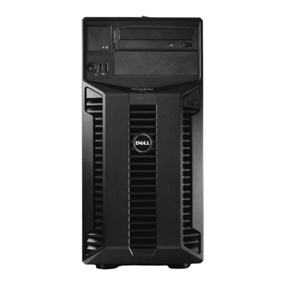
Page 13: Front Panel View And Features
Dell Front Panel View and Features Figure 2, Figure 3, and Figure 4 show the front views of the PowerEdge T410. Figure 2. Front View (With Bezel) Figure 3. Front View (Cabled Hard Drive Chassis Without Bezel) PowerEdge T410 Technical Guide... -
Page 14: Back Panel View And Features
PowerEdge T410 Hardware Owner’s Manual on Support.Dell.com for more information. Back Panel View and Features Figure 5 and Figure 6 show the back views of the PowerEdge T410. Figure 5. Back View (With Non-redundant Power Supply) PowerEdge T410 Technical Guide... -
Page 15: Hard Drive Led Indicators
Dell PowerEdge T410 Systems Hardware Owner’s Manual on Support.Dell.com. Power Supply Indicators The PowerEdge T410 optional redundant power supplies have one status bi-color LED: green for AC power present and amber for a fault as detailed in Table 3. -
Page 16: Nic Indicators
DC Power is applied to the system Redundant power supply mismatch ↔ (when hot-plugged/swapped) See the Power Indicator Codes section in the About Your System chapter of the PowerEdge T410 Hardware Owner’s Manual on Support.Dell.com for more information. NIC Indicators See the NIC Indicator Codes section in the About Your System chapter of the PowerEdge T410 Hardware Owner’s Manual on... -
Page 17: Rails And Cable Management
Internal View (Hot-plug Hard Drive Configuration) Rails and Cable Management The PowerEdge T410 is not a rackable system and does not have a rack kit. However, the T410 can be stored in a rack using a third-party rack tray. For information on power-cord cable-management, see the Installation and Configuration section in the Dell PowerEdge T410 Getting Started Guide on Support.Dell.com. -
Page 18: Led Panel Configuration
Non-maskable Interrupt (NMI) button (recessed) For more information on the LCD panel, see the LCD Panel Features (Optional) section in the About Your System chapter in the PowerEdge T410 Hardware Owner’s Manual on Support.Dell.com. 4.11.2 LED Panel Configuration Figure 10 shows the LED control panel. -
Page 19: Security
For additional information regarding the following security features, see the PowerEdge T410 Hardware Owner’s Manual on Support.Dell.com. 4.12.1 Cover Latch The PowerEdge T410 comes with a tooled latch on the side cover of the system that secures it to the chassis. A lock secures the cover latch. 4.12.2 Bezel A bezel is mounted to the front of the chassis. -
Page 20: Battery
Field Replaceable Units (FRU) 4.15 The planar contains a 16K x 8 serial EEPROM to store FRU information including Dell part number, part revision level, and serial number. This part is also used as a system event log (SEL) to be used by the baseboard management controller (BMC). -
Page 21: Power, Thermal, Acoustic
5 Power, Thermal, Acoustic Power Supplies The PowerEdge T410 system includes a single non-redundant 525W power supply or an optional redundant 580W power supply. The power supply subsystem provides power to the planar, six internal hard drive bays (cabled hard drive chassis), the hard drive backplane (hot-plug hard drive chassis), and the two 5.25‖... -
Page 22: Environmental Specifications
Dell Environmental Specifications Table 6 summarizes the environmental specifications for the PowerEdge T410. Table 6. Environmental Specifications Temperature 10° to 35°C (50° to 95°F) with a maximum temperature gradation of 10°C per hour Operating Note: For altitudes above 2950 feet, the maximum operating temperature is derated 1°F/550 ft. -
Page 23: Acoustics
Sound quality is different from sound power level and sound pressure level in that it describes how humans respond to annoyances in sound, like whistles or hums. One of the sound quality metrics in the Dell specification is prominence ratio of a tone as shown in Table 7. Table 7. -
Page 24: Processors
The Intel Xeon processor 5500 and 5600 series uses a 1366-contact Flip-Chip Land Grid Array (FC-LGA) package that plugs into a surface mount socket. The PowerEdge T410 provides support for up to two processors. Table 8. Intel Xeon 5500 and 5600 Processor Series Overview... -
Page 25: Features
SSL (5600 series) Intel TXT (Trusted Execution Technology) provides hardware assisted protection against emerging software attacks (5600 series) Supported Processors For the latest information on supported processors for the PowerEdge T410, visit Dell.com. Table 9. Supported Processors Model Speed... -
Page 26: Processor Configurations
4.8GT/s Processor Configurations The PowerEdge T410 will operate with either a single processor or dual processors. However, since the memory controller is embedded in the processor, when only one processor is installed in the system, it supports 4 DIMMs, minimum 1GB and maximum 64GB. When two processors are installed in the system, it supports 8 DIMMs, minimum 2GB and maximum 128GB. -
Page 27: Memory
Dell 7 Memory Overview The PowerEdge T410 utilizes DDR3 memory, providing a high performance, high-speed memory interface capable of low latency response and high throughput. The T410 supports Registered ECC DDR3 DIMMs (RDIMM) or Unbuffered ECC DDR3 DIMMs (UDIMM). Key features of the T410 memory system include: ... -
Page 28: Dimm Slots
Xeon processor 5600 series, low voltage (LV) DIMMs have been added for selected memory configurations for the PowerEdge T410. Only this processor series supports operating DIMMs at the lower voltage (1.35V, also referred to as DDR3L). The Intel Xeon 5500 processor series does not support low voltage operation. However, they can be operated at 1.5V. -
Page 29: Mirroring
Setup program. In a mirrored configuration, the total available system memory is one-half of the total installed physical memory. Supported Configurations See the System Memory section in the Installing System Components chapter in the Dell PowerEdge T410 Systems Hardware Owner's Manual on Support.dell.com. PowerEdge T410 Technical Guide... -
Page 30: Chipset
5600 series includes a stepping revision of the Intel 5520 and 5500 chipset, which is required to enable the full 5600 series feature set. Dell servers shipped with the new chipset revision have the symbol II in the System Revision Field visible through Dell OpenManage™... -
Page 31: Smbus Interfaces
5500 chipset MCH to the ICH10R. The ESI interface runs at 2 GB/s with a 100 MT/s reference clock. Intel ICH10R South Bridge The PowerEdge T410 planar incorporates the Intel ICH10R chip. The ICH10R is a highly integrated I/O controller. 8.3.1... -
Page 32: Bios
Dell 9 BIOS Overview The T410 BIOS is based on the Dell BIOS core, supporting the following features: ® Intel 5500 2S support Simultaneous Multi-Threading (SMT) support CPU Turbo Mode support PCI 2.3 compliant Plug and Play 1.0a compliant ... -
Page 33: Bios Power Management
C-bus. This solves the many interfacing problems encountered when designing digital control circuits. These I C devices perform communication functions between intelligent control devices (such as microcontrollers), general-purpose circuits (such as LCD drivers, remote I/O ports, memories), and application-oriented circuits. PowerEdge T410 Technical Guide... -
Page 34: Embedded Nics/Lan On Motherboard (Lom)
5716 dual-port LAN controller is on the T410 planar as an independent Gigabit Ethernet interface device. There are two RJ-45 connectors on the back of the system. The firmware for the LOM chip resides in a flash part. The PowerEdge T410 supports Wake-On-LAN (WOL) from either port. PowerEdge T410 Technical Guide... -
Page 35: O Slots
Dell 11 I/O Slots Overview 11.1 The PowerEdge T410 has five PCI Express expansion slots which are detailed as follows: One x16 PCIe Gen2 slot for a full-height half-length card Two x8 PCIe Gen2 slots for full-height full-length cards ... -
Page 36: Storage
6 x 2.5‖ hot-plug SAS, SATA, or SSD drives using an optional storage controller The use of 2.5‖ hard drives requires the hot-plug chassis configuration and the Dell 3.5‖ hard drive carrier and retention kit. Upgrading between cabled and hot-plug configurations is not possible after purchase. - Page 37 (SAS 6/iR, PERC 6/i, PERC H200, PERC H700) SAS/SATA ASSR5 Add-in SAS/SATA RAID card, RAID 5 /SSD—RAID 1 (PERC H700) + RAID 1 SAS/SATA ASSR6 Add-in SAS/SATA RAID card, RAID 6 /SSD—RAID 1 (PERC H700) + RAID 5 PowerEdge T410 Technical Guide...
-
Page 38: Storage Controllers
Storage Controllers 12.4 The PowerEdge T410 supports the storage controllers listed below. For information on card quantities and priorities, see the Expansion Cards section in the Installing System Components chapter of the Dell PowerEdge T410 Systems Hardware Owner’s Manual on Support.dell.com. -
Page 39: Perc H200
256MB and 512MB cache options on the internal H700. 12.4.5 PERC H800 The PowerEdge T410 can support up to two PERC H800 adapter cards installed in the PCI Express x8 slots for access to external SAS direct-attach storage. Features of the PERC H800 include: ... -
Page 40: Video
Dell 13 Video ® The PowerEdge T410 is equipped with a Matrox G200eW with 8 MB memory integrated in the ® Nuvoton WPCM450 (Baseboard Management Controller [BMC]). Supported resolutions are listed in Table 13. Table 13. Graphics Video Modes Resolution... -
Page 41: Rack Information
Dell 14 Rack Information Dell does not provide rack support for the PowerEdge T410. However, the system can be placed in a rack enclosure using a 3 party tray. PowerEdge T410 Technical Guide... -
Page 42: Operating Systems
Dell 15 Operating Systems For detailed information, see the following: Operating System Support Matrix for Dell PowerEdge Systems on Dell.com Dell PowerEdge T410 Systems Getting Started Guide on Support.Dell.com PowerEdge T410 Technical Guide... -
Page 43: Systems Management
IT assets. Combining Dell PowerEdge Servers with a wide selection of Dell developed systems management solutions gives you choice and flexibility, so you can simplify and save in IT environments of any size. To help you meet your server management demands, Dell offers Dell OpenManage™ systems management solutions for: •... -
Page 44: Embedded Server Management
Dell Unified Server Configurator (USC) is a graphical user interface (GUI) that aids in local server provisioning in a pre-OS environment. To access the Unified Server Configurator, press the <F10> key within 10 seconds of the Dell logo appearance during the system boot process. Table 14 details the current functionality enabled by the USC. -
Page 45: Integrated Dell Remote Access Controller
Integrated Dell Remote Access Controller 16.5 The integrated Dell Remote Access Controller (iDRAC6) provides IT Administrators comprehensive yet straightforward management of remote servers, by delivering ―as if you are there‖ presence and control. iDRAC6 helps users to save time and money by eliminating travel to the remote server(s), whether that server is located in a different room, a different building, a different city, or in a different country. -
Page 46: Idrac6 Enterprise With Virtual Flash (Vflash) Media
Enterprise with Virtual Flash (vFlash) Media 16.8 The iDRAC6 Enterprise can be upgraded by adding the vFlash media card. This is an 8 GB Dell-branded SD card that enables a persistent 256 MB virtual flash partition. The vFlash media delivers the following key features: ... - Page 47 Monitoring Real-time Power Graphing Historical Power Counters Logging Features System Event Log RAC Log Trace Log PowerEdge T410 Technical Guide...
-
Page 48: Peripherals
Dell 17 Peripherals The T410 supports the following USB devices: DVD-ROM DVD+RW USB key (bootable) PowerEdge T410 Technical Guide... -
Page 49: Appendix A. Statement Of Volatility
Appendix A. Statement of Volatility The Dell PowerEdge T410 contains both volatile and non-volatile (NV) components. Volatile components lose their data immediately upon removal of power from the component. Non-volatile components continue to retain their data even after the power has been removed from the component. - Page 50 TPM (Trusted Platform Module; boards sold to Details destinations in China do not have TPM at this time.) Size: Unspecified size of user ROM, RAM, EEPROM; 128 bytes of OTP memory included Type: [e.g. Flash PROM, EEPROM]: ROM, RAM, EEPROM PowerEdge T410 Technical Guide...
- Page 51 How is data input to this memory? Factory installed or via USB bus. How is this memory write protected? Not write protected Remarks Server BMC (Baseboard Management Details Controller) Firmware Flash Memory Size: 16MB Flash Type: [e.g. Flash PROM, EEPROM]: SPI Flash PowerEdge T410 Technical Guide...
- Page 52 How is this memory write protected? Software write protected Remarks To obtain optional component information, please refer to the Dell Statement of Volatility for the individual components. Please direct any questions to your Dell Marketing contact. PowerEdge T410 Technical Guide...
-
Page 53: Appendix B. Certifications
OTAN – CKT Kenya KEBS Kuwait KUCAS Mexico NYCE or NOM Moldova INSM Nigeria SONCAP Norway NEMKO Russia GOST Saudi Arabia KSA ICCP South Africa NRCS Taiwan BSMI UKRTEST or Ukraine UKRSERTCOMPUTER United States NRTL Uzbekistan PowerEdge T410 Technical Guide... -
Page 54: Electromagnetic Compatibility
NEMKO Class A Russia GOST Class A South Africa SABS Class A South Korea Class A Taiwan BSMI Class A Ukraine UKRTEST or UKRSERTCOMPUTER Class A United States Class A Uzbekistan Class A Vietnam Class A PowerEdge T410 Technical Guide... -
Page 55: Ergonomics, Acoustics And Hygienics
The product has been certified and bears the Mark, as applicable, of the Ergonomics, Acoustics and Hygienics authorities as indicated in Table 19. Table 19. Ergonomics, Acoustics and Hygienics Country/Region Authority or Mark Belarus BELLIS Germany Russia GOST PowerEdge T410 Technical Guide... -
Page 56: Additional Information And Options
Dell Appendix C. Additional Information and Options The PowerEdge T410 system conforms to the industry standards detailed in Table 20. Table 20. Industry Standards Standard URL for Information and Specifications ACPI http://www.acpi.info/ Advance Configuration and Power Interface Specification, v2.0c Energy Star http://www.energystar.gov/index.cfm?c=archives.enterprise_servers... - Page 57 Dell Standard URL for Information and Specifications http://www.usb.org/developers/docs/ Universal Serial Bus Specification, Rev. 2.0 Windows Logo http://www.microsoft.com/whdc/winlogo/hwrequirements.mspx Windows Logo Program System and Device Requirements, v3.10 PowerEdge T410 Technical Guide...