Table of Contents
Advertisement
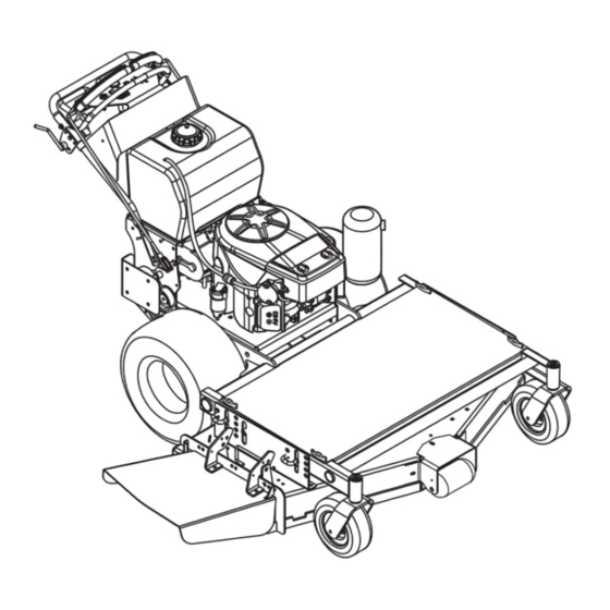
Pro Unit
Owner/Operator Manual
Models
988100 - GR1336FX
988101 - GR1536FX
988102 - GR1548FX
988103 - GR1548FL
988104 - GE1748FL
988110 - GR1332FX
988112 - GR1544FX
988114 - GR1336FXP
988115 - GR1548FXP
988118 - GR1332FXP
988119 - GR1544FXP
988313 - GR1332FXPCE
ENGLISH
FRANÇAIS
ESPAÑOL
04941300 7/03
Printed in USA
Advertisement
Table of Contents

Related Manuals for Gravely 988100-GR1336FX, 988101-GR1536FX, 988102-GR1548FX, 988103-GR1548FL, 988104-GE1748FL, 988110-GR1332FX, 988112-GR1544FX, 988114-GR


Summary of Contents for Gravely 988100-GR1336FX, 988101-GR1536FX, 988102-GR1548FX, 988103-GR1548FL, 988104-GE1748FL, 988110-GR1332FX, 988112-GR1544FX, 988114-GR
- Page 1 Pro Unit Owner/Operator Manual Models 988100 - GR1336FX 988101 - GR1536FX 988102 - GR1548FX 988103 - GR1548FL 988104 - GE1748FL 988110 - GR1332FX 988112 - GR1544FX 988114 - GR1336FXP 988115 - GR1548FXP 988118 - GR1332FXP 988119 - GR1544FXP 988313 - GR1332FXPCE ENGLISH FRANÇAIS ESPAÑOL...
- Page 2 firmante - Undertegnede, - Undertecknaren av detta dokument, - Me, allekirjoittaneet, ARIENS COMPANY, declare that the Lawn Mower- certifie que la tondeuse à gazon - erklärt, dass der Rasenmäher - verklaart dat de maaitrekker - dichiara che il tosaerba - certifica que el cortacésped - erklærer, at græsslåmaskinen - erklærer at plenklipperen - intygar att gräsklipparen:...
- Page 3 Stated Sound Power Levels are established following Annex VIII “Full Quality Assurance” of directive 2000/14/EC. Les déclarations de niveau de puissance acoustique sont établies conformément à l’Article VIII « Assurance qualité totale » de la directive 2000/14/EC. Die angegebenen Geräuschpegel wurden gemäß Anhang VIII „Totales Qualitäts-Management“ der EU-Richtlinie 2000/14/EC.
- Page 4 ENGLISH 17. Pivot Bar (988114,115, 118, 119, 313) 1. Shift Lever 18. Control Stop Lock Lever 2. Steering Lever Latches (988114,115, 118, 119, (988100, 101, 102, 103, 313) 104, 110, 112) 3. Steering Levers (988100, FRANÇAIS 101, 102, 103, 104, 110, 1.
-
Page 5: Table Of Contents
Warranty....... . 29 INTRODUCTION PRODUCT REGISTRATION The Gravely dealer must register the product at the time of purchase. Registering the product will help the company process warranty claims or contact you with the latest service information. - Page 6 5. Explain recommended lubrication and maintenance. Advise customer on adjustments. WARNING: This cutting machine is capable of amputating hands and feet and throwing objects. Failure to observe the safety instructions in the manuals and on decals could result in serious injury or death. Slopes are a major factor related to loss-of-control and tip-over accidents.
-
Page 7: Safety Rules
TO AVOID SERIOUS INJURY OR DEATH: • Read the operator's manual. • Keep children and others away from unit while operating. • Never direct discharge toward other people. Thrown objects can cause injury. • Keep safety devices (guards, shields, switches, etc.) in place and working. • Check interlock system per manual before use. - Page 8 Complete a walk around inspection of unit and work area to understand: • Work area • Your unit • All safety decals ALWAYS check overhead and side clearances carefully before operation. ALWAYS be aware of traffic when operating along streets or curbs. Keep children and people away.
- Page 9 Disengage PTO when attachment is not in use. DO NOT raise deck with blades running. ALWAYS turn off power to attachment when travelling, crossing driveways, etc. Avoid uneven and rough terrain. DO NOT operate near drop offs, ditches, or embankments. Unit can suddenly turn over if a wheel is over the edge of a cliff or ditch, or if an edge caves in.
-
Page 10: Controls And Features
DO NOT TIP battery beyond a 45° angle in any direction. ALWAYS keep batteries out of reach of children. Before making any inspections, repairs, etc.: disengage PTO, stop unit and engine, remove key, allow moving parts to stop. Allow hot parts to cool. ALWAYS block wheels, engage parking brake and know all jack stands are strong, secure and will hold weight of unit during maintenance. - Page 11 Steering Levers (988100, 101, 102, 103, 104, 110, 112) WARNING: AVOID INJURY. When the engine is running and the shift lever is engaged, releasing only one steering latch causes the unit to circle around one drive wheel. ALWAYS hold both steering levers in the neutral position when releasing the steering lever latches.
- Page 12 PTO Clutch (988114, 115, 118, 119, 313) Pull the PTO (power take off) switch past On (1) to Reset (2) to engage the mower blades. Push the PTO switch Off (3) to disengage the mower blades. NOTE: Pull PTO switch to Reset (2) to engage mower blades after operator presence control has been released.
- Page 13 6. Grasp recoil starter handle and pull rope out slowly until it pulls harder. This is the compression stroke. 7. Let the rope rewind slowly. 8. Pull rope with rapid continuous full arm stroke to start engine. Allow rope to rewind slowly. IMPORTANT: DO NOT let starter handle snap against engine.
- Page 14 WARNING: AVOID INJURY. When the engine is running and the shift lever is engaged, releasing only one steering latch causes the unit to circle around one drive wheel. ALWAYS hold both steering levers in the neutral position when releasing the steering lever latches.
-
Page 15: Cutting Height Adjustment
• To move straight forward, slowly push control levers forward. • To stop unit motion, allow control levers to return to neutral. • To turn to the left, push the right hand control lever forward. • To turn to the right, push the left hand control lever forward. - Page 16 NOTE: It may be necessary to adjust cutting height in steps to keep deck from binding. Floating Deck Cutting Heights Inches (mm) Figure 6 LAWN STRIPER ADJUSTMENT (44" and 48" decks; optional on 32" and 36" decks) The striper drags behind the deck and shapes grass as you mow.
-
Page 17: Maintenance
WARNING: AVOID INJURY. Read and understand the entire Safety section before proceeding. MAINTENANCE SCHEDULE Each Check Safety Interlock • System • Check Air Cleaner • Check Engine Oil • Check Engine Cooling • Check Fasteners • Check Tire Pressure Check Battery and Battery Fluid Check All Belts Mower Blades... -
Page 18: Service And Adjustments
CHECK BATTERY (988104) WARNING: AVOID INJURY. Read and understand the entire Safety section before proceeding. WARNING: Battery posts, terminals and related accessories contain lead and lead compounds, chemicals known to the State of California to cause cancer and reproductive harm. Wash hands after handling. Terminals Inspect battery and terminals every 25 hours. - Page 19 5. Adjust tracking if needed. Try each of the following steps until the unit tracks straight. It may not be necessary to perform all the steps. If unit turns to the right 1. Reduce the air pressure in the left tire. 2.
- Page 20 Brake Rod Note: Some components removed for clarity. Figure 9 REPLACE TRACTION BELTS 1. Turn off the engine, remove the key and allow unit to cool. 2. Release the steering levers (988100, 101, 102, 103, 104, 110, 112). 3. Raise the rear of the unit so that the drive wheels are off the ground.
-
Page 21: Clutch Adjustment
ADJUST SHIFT LEVER LINKAGE The transmission shift lever is attached to the transmission shift arm with two 5/16-18 bolts (Figure 11). 1. Transmission 3. 5/16-18 Bolts 2. Shift Lever Figure 11 To adjust: 1. Stop the engine. Remove ignition key. Put PTO lever in the "OFF"... - Page 22 3. Repeat for each inspection slot. To adjust: 1. If necessary, loosen gap adjustment nuts until a .005" feeler gauge fits between armature and rotor. 2. Slide a .012" feeler gauge between armature and rotor. 3. Tighten gap adjustment nut until there is slight contact on feeler gauge.
- Page 23 5. Make the final jumper cable connection to the engine block or the furthest ground point away from the discharged battery. WARNING: Make sure cables are clear of any moving engine parts before starting engine. 6. Start engine (See Starting and Shut Off on page 12).
-
Page 24: Mower Blades
MOWER BLADES NOTE: If mower is used under sandy soil conditions, replace blades when air lifts become eroded through at ends (Figure 18). DO NOT sharpen to this pattern Sharpen to this pattern DISCARD if more than 1/2 in. (1.27 cm) 1. -
Page 25: Storage
WARNING: AVOID INJURY. Read and understand the entire Safety section before proceeding. Storage – Two Months or More Check each item in the Maintenance Schedule on page 17, but do not add gasoline. Clean the unit. Touch up all scratched painted surfaces. IMPORTANT: Never spray unit with high-pressure water or store unit outdoors. -
Page 26: Accessories
PROBLEM PROBABLE CAUSE Unit pulls 1. Steering levers out of sharply to the adjustment. left or right when the speed control levers are quickly moved all the way forward Unit does not straighten immediately when the steering levers are released Unit loses power 1. -
Page 27: Specifications
Model Number 988100 Description GR1336FX Length – in (cm) Height – in (cm) Width – in (cm) Actual Weight – lbs (kg) Battery Brakes Turning Radius – in. (cm) Tire Size Engine – Manufacturer Kawasaki FH381V-BS04 Cycle Horsepower – HP (Kw) @ 13 (9.7) 3600 RPM Starting System... - Page 28 Model Number 988112 Description GR1544FX Length – in (cm) 75.5 (191.8) Height – in (cm) 42 (106.7) Width – in (cm) 47.0 (119.38) Actual Weight – lbs (kg) 560 (254.5) Battery Brakes Turning Radius – in. (cm) Tire Size Engine – Manufacturer Kawasaki FH430V-BS06 Cycle...
-
Page 29: Warranty
• Four to twelve months - Prorated over 12 months Gravely may from time to time change the design of its products. Nothing contained in this warranty shall be construed as obligating Gravely to incorporate such design changes into previously manufactured products, nor shall such changes be construed as an admission that previous designs were defective. - Page 30 GRAVELY A Division of Ariens Company 655 West Ryan Street P.O. Box 157 Brillion, WI 54110-0157 920-756-2141 Fax 920-756-2407 www.gravely.com...