Table of Contents
Advertisement
Advertisement
Table of Contents

Related Manuals for Nady Systems 4W-1KU


Summary of Contents for Nady Systems 4W-1KU
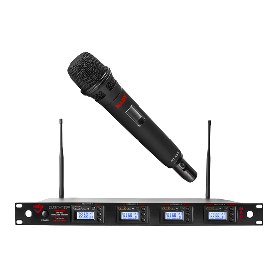
- Page 1 O W n e R ’ S M a n U a l 4W-1KU 1000-Channel UHF Quad Receiver Wireless System...
-
Page 2: Table Of Contents
Introduction Thank you for choosing the Nady 4W-1KU QUAD wireless system, and congratulations on your choice. The Nady 4W-1KU QUAD wireless system has the best performance and price value in professional UHF wireless, offering clear-channel, frequency-agile operation on the UHF band for interference-free performance in any application or locale. The Nady... -
Page 3: System Features
System Features 4W-1KU Receiver HT-1KU Handheld and BT-1KU Bodypack Transmitters • Unsurpassed state-of-the-art PLL UHF performance with 120dB dynamic range • Choice of transmitters: HT-1KU or BT-1KU, and operation up to 500 feet line-of sight all with 1000 easily selectable channels: manually with up/down buttons on units or •... -
Page 4: Quick User Controls Guide
Quick User Controls Guide 4W-1KU Receiver: Front View RECEIVER 1 RECEIVER 2 RECEIVER 3 RECEIVER 4 GROUP CHANNEL GROUP CHANNEL GROUP CHANNEL GROUP CHANNEL POWER GROUP CHANNEL POWER BUTTON Press for one second to turn SET To scroll through the LCD menu and... - Page 5 4W-1KU Receiver: Back View DC 12~18V IN 1000mA ANT-A ANT-B CH 4 MIC OUT CH 3 MIC OUT CH 2 MIC OUT CH 1 MIC OUT UNBALANCED MUTE-4 BALANCED MUTE-3 BALANCED MUTE-2 BALANCED MUTE-1 BALANCED LINE (Optional) 17. UNBALANCED AUDIO OUT SUM Volume Level 13.
- Page 6 Quick User Controls Guide HT-1KU Handheld Transmitter 22. BATTERY COVER Unscrew CW and full down 28. POWER ON/OFF SWITCH Slide power switch to insert two AA alkaline batteries up-down to turn ON-OFF 23. MIC BALL Windscreen/dust cover 29. INTERNAL ANTENNA Built-in antenna 24.
- Page 7 Quick User Controls Guide BT-1KU Bodypack Transmitter (lT, lT/HM or GT) 37. INPUT JACK 3.5mm locking mini jack for 42. SET BUTTON To scroll LCD menu and set the connecting audio input cord from lapel mic selected program/function (LT), Headmic (LT/HM), or instrument (GT) ™...
-
Page 8: System Operation
A transmitter should be used display “OFF” indicating the receivers at this time to receive data from the are off. At power-off the 4W-1KU QUAD receiver (see IR Sync Programming in receivers will store the last settings entered Programming sections of HT-1KU and and re-display them at power-on. - Page 9 Setup Mode by pressing the Set Button onto the two RF Connectors (14/19) located one more time. Selecting 0 should mute on the back of the 4W-1KU QUAD receiver. the receiver and no output for the Line Out The two antennas must be installed in order only.
-
Page 10: Adjusting The Squelch
Peak leD Indicator the amplifier or mixing board volume is at the minimum level before plugging in the receiver to The 4W-1KU QUAD receiver has an aF Peak avoid possible sound system damage. leD (3) display for each receiver and each works independently per channel. -
Page 11: Ht-1Ku Handheld Microphone Transmitter
Powering the Transmitter On/Off HT-1KU Handheld To turn on the transmitter, slide the Power Microphone Transmitter On/Off Switch (28) to the “ON” position. The LCD backlight will light up, indicating the unit Buttons Function is now on. After ten seconds the backlight will automatically turn off to conserve battery The RF Power level Switch (27) is used to life. - Page 12 about 6-12” from the receiver to be used. to change in four steps from 0dB to -30dB On the receiver, when short pressing the (for loudest input) or press the Set button a aSC IR Sync Button (5), while the main menu second time to exit to the main menu.
-
Page 13: Bt-1Ku Bodypack Transmitter
Setting up the Transmitter this setting for normal use not requiring maximum operating range. A range walk The BT-1KU bodypack requires two test before use will determine which setting aa Batteries (50) to operate. To install the is best for your application. batteries into the battery compartment, lift the Battery Compartment Door (46) by grabbing Slide the On/Off switch to the “ON”... - Page 14 and should be replaced as soon as possible. Note: If procedure is not done correctly during the three seconds of active data transfer, the receiver To preserve battery life, turn the transmitter and the transmitter do not link and transmitter’s off when not in use.
- Page 15 is Group 00 (Transmitter 1), 03 (Transmitter To mute, slide the power switch to “MUTE” 2), 06 (Transmitter 3) and 09 (Transmitter 4), again. Adjust the volume of the receiver per and Channel 00 for all transmitters. After Connecting Audio Outputs section above. programming is finished, close the battery Note: Avoid acoustic feedback (howling or compartment door, ensuring that it latches.
-
Page 16: Specifications
<0.5% Modulation FM (F3E) +/-25kHz normal, +/-75kHz max Operating Range 150-250 feet typical, 500+feet max line-of-sight 4W-1KU QUaD ReCeIVeR SPeCIFICaTIOnS Receiver System Dual conversion Super Heterodyne with True Diversity (two complete receiver sections with optimum audio selected) Selectivity 60dB, normal +/-75kHz offset... -
Page 17: Cautions And Troubleshooting
To reprogram, you must first find an open channel. To do this, follow the operating Avoid acoustic feedback (howling or procedure outlined in Selecting the 4W-1KU screeching) by taking care in selecting Receiver Volume Level / Group / Channel. PA volume, transmitter location and With the associated transmitter off, scroll speaker placement. -
Page 18: Miscellaneous Tips
Miscellaneous Tips • For the best operation, the receiver should • For optimal operation with external be placed at least 3 ft. (1 m) above the antennas, low loss RF shielded cable ground and 3 ft. (1 m) away from a wall or should be used and the length of the cable should not exceed 10 ft. -
Page 19: Frequency
Include a brief description of the problem you are experiencing. For service of a unit under warranty, please follow the instructions in the following section. Outside the U.S For service or warranty matters please contact the Nady distributor in your country through the dealer/store from which you purchased this product. -
Page 20: Warranty
Nady Systems, Inc. for repair. The warranty is null and void if any Nady serial number has been removed or defaced.