Table of Contents
Advertisement
Advertisement
Table of Contents

Related Manuals for Nady Systems 2W-1KU


Summary of Contents for Nady Systems 2W-1KU
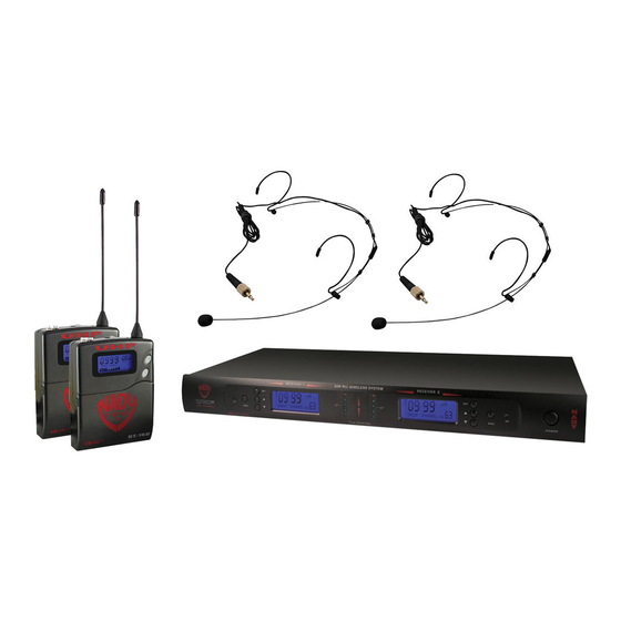
- Page 1 O W n e R ’ S M a n U a l 2W-1KU 1000-Channel UHF Dual Receiver Wireless System...
-
Page 2: Table Of Contents
Introduction Thank you for choosing the Nady 2W-1KU wireless system, and congratulations on your choice. The Nady 2W-1KU wireless system has the best performance and price value in professional UHF wireless, offering clear-channel, frequency-agile operation on the UHF band for interference-free performance in any application or locale. The Nady 2W-1KU... -
Page 3: System Features
System Features 2W-1KU Receiver HT-1KU Handheld and BT-1KU Bodypack Transmitters • Unsurpassed state-of-the-art PLL UHF performance with 120dB dynamic range • Choice of transmitters: HT-1KU or BT-1KU, and operation up to 500 feet line-of sight all with 1000 easily selectable channels: manually with up/down buttons on units or •... -
Page 4: Quick User Controls Guide
Quick User Controls Guide 2W-1KU Receiver: Front View RECEIVER 1 RECEIVER 2 GROUP CHANNEL GROUP CHANNEL 2W-1KU DUAL True Diversity GROUP CHANNEL IR Infrared LED transmitter window for linking AF/PEAK LEDS Shows GREEN LEDs for normal the RX to the TX for frequency download... - Page 5 2W-1KU Receiver: Back View BALANCED BALANCED DC13~15V MIXED MIC-1 + MIC-B 500mA UNBALANCED MIN MAX MIN MAX SUM OUT POWER ANT-B MUTE 2 MIC-2 OUT MIC-1 OUT MUTE 1 ANT-A (Optional) 14. DC INPUT JACK For using supplied external 19. DC POWER SUPPLY UNIT DC16VDC/800mA...
- Page 6 Quick User Controls Guide HT-1KU Handheld Transmitter 24. BATTERY COVER Unscrew to insert two UP BUTTON To change the GRP/CH or VOL AA alkaline batteries level up by one step at a time or to light up the display 25. MIC BALL Windscreen/dust cover DOWN BUTTON To change the GRP/CH or 26.
- Page 7 Quick User Controls Guide BT-1KU Bodypack Transmitter (lT, lT/HM or GT) 39. LCD DISPLAY For indication of GRP (00-09)/ 44. SET BUTTON To scroll LCD menu and set the CH (00-99), AUDIO INPUT LEVEL (0dB to selected program/function -30dB), and BATTERY status (5 bars to 1 45.
-
Page 8: System Operation
(see IR Sync Programming will turn off indicating the receivers are off. in Programming sections of HT-1KU At power-off the 2W-1KU receivers will and BT-1KU transmitter sections). store the last settings entered and re-display Upon successful data transferred (usually them at power-on. -
Page 9: Installing Antennas
(20) included with your system onto the two RF Connectors (15) located Choose the 2W-1KU operating frequency on the back of the 2W-1KU receiver. The by selecting one of ten Groups (9) and one two antennas must be installed in order to of 100 Channels (10) that are determined to the diversity circuit to work properly. -
Page 10: Adjusting The Squelch
Squelch Connecting the audio Outputs The 2W-1KU receiver has one Unbalanced In normal operation, each 2W-1KU receiver’s audio SUM Out (18) adjustable line level Mute Control (16) works independently and audio output and two Balanced XlR Mic should be adjusted clockwise (CW) to the... -
Page 11: Ht-1Ku Handheld Microphone Transmitter
Powering the Transmitter On/Off HT-1KU Handheld Microphone Transmitter To turn on the transmitter, slide the Power On/Off Switch (34) to the “ON” position. The LCD backlight will light up, Buttons Function indicating the unit is now on. After ten seconds the backlight will automatically The RF Power level Switch (33) is used to turn off to conserve battery life. -
Page 12: Handheld Transmitter
IR Sync Programming: press the Set button again for the channel Use the wireless IR leD Receptor Sensor (36) selection. The Channel Icon (28) will now to download pre-programmed channels flash. Again, use the Up/Down buttons to from the receiver. Start programming by change the channel as desired. -
Page 13: Bt-1Ku Bodypack Transmitter
Setting up the Transmitter setting increases battery life and also optimizes the number of channels that can The BT-1KU bodypack requires two AA size be used simultaneously in a given location. batteries to operate. To install the batteries Use this setting for normal use not requiring into the battery compartment, lift the maximum operating range. - Page 14 should be replaced as soon as possible. To Note: If procedure is not done correctly during the three seconds of active data transfer, the receiver preserve battery life, turn the transmitter off and the transmitter do not link and transmitter’s when not in use.
-
Page 15: Bodypack Transmitter
For normal operation, the transmitter should be on, indicating a received signal from the have the same Group/Channel as displayed transmitter. When ready to transmit audio, on the receiver. The default factory setting slide the power switch to “ON” to un-mute. is Group 00 (Transmitter 1), 03 (Transmitter To mute, slide the power switch to “MUTE”... -
Page 16: Specifications
<0.5% Modulation FM (F3E) +/-25kHz normal, +/-75kHz max Operating Range 150-250 feet typical, 500+feet max line-of-sight 2W-1KU ReCeIVeR SPeCIFICaTIOnS Receiver System Dual conversion Super Heterodyne with True Diversity (two complete receiver sections with optimum audio selected) Selectivity 60dB, normal +/-75kHz offset... -
Page 17: Cautions And Troubleshooting
To reprogram, you must first find an open channel. To do this, follow the operating Avoid acoustic feedback (howling or procedure outlined in Selecting the 2W-1KU screeching) by taking care in selecting Receiver Volume Level / Group / Channel. PA volume, transmitter location and With the associated transmitter off, scroll speaker placement. -
Page 18: Miscellaneous Tips
Miscellaneous Tips • For the best operation, the receiver should • For optimal operation with external be placed at least 3 ft. (1 m) above the antennas, low loss RF shielded cable ground and 3 ft. (1 m) away from a wall or should be used and the length of the cable should not exceed 10 ft. -
Page 19: Frequency
Nady Service Department. Ship your unit prepaid to: Nady Systems, Service Department, 6701 Shellmound Street, Emeryville, CA 94608. Include a brief description of the problem you are experiencing. For service of a unit under warranty, please follow the instructions in the following section. -
Page 20: Warranty
Nady Systems, Inc. for repair. The warranty is null and void if any Nady serial number has been removed or defaced.