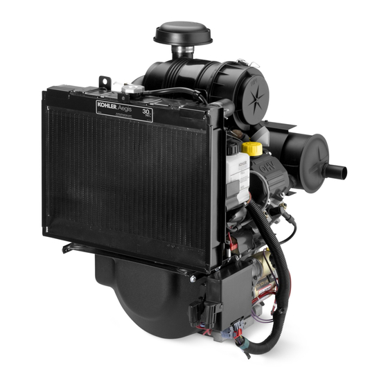
Kohler Aegis LH775 Service Manual
Horizontal-shaft
Hide thumbs
Also See for Aegis LH775:
- Owner's manual (21 pages) ,
- Service manual (177 pages) ,
- Owner's manual (12 pages)
Table of Contents
Advertisement
Quick Links
LH775
Service Manual
IMPORTANT:
Read all safety precautions and instructions carefully before operating equipment. Refer to operating
instruction of equipment that this engine powers.
Ensure engine is stopped and level before performing any maintenance or service.
2
Safety
3
Maintenance
5
Specifi cations
11
Tools and Aids
14
Troubleshooting
18
Air Cleaner/Intake
19
Electronic Fuel Injection (EFI) System
45
Lubrication System
47
Electrical System
51
Starter System
55
Cooling System
59
Disassembly/Inspection and Service
75
Reassembly
66 690 07 Rev. --
KohlerEngines.com
1
Advertisement
Table of Contents
Troubleshooting

Related Manuals for Kohler Aegis LH775


Summary of Contents for Kohler Aegis LH775
- Page 1 LH775 Service Manual IMPORTANT: Read all safety precautions and instructions carefully before operating equipment. Refer to operating instruction of equipment that this engine powers. Ensure engine is stopped and level before performing any maintenance or service. Safety Maintenance Specifi cations Tools and Aids Troubleshooting Air Cleaner/Intake...
-
Page 2: Safety Precautions
Safety SAFETY PRECAUTIONS WARNING: A hazard that could result in death, serious injury, or substantial property damage. CAUTION: A hazard that could result in minor personal injury or property damage. NOTE: is used to notify people of important installation, operation, or maintenance information. CAUTION WARNING WARNING... -
Page 3: Maintenance Instructions
Perform these procedures more frequently under severe, dusty, dirty conditions. REPAIRS/SERVICE PARTS Kohler genuine service parts can be purchased from Kohler authorized dealers. Find your local Kohler Engines dealer at KohlerEngines.com or call 1-800-544-2444 (U.S.A. and Canada). 66 690 07 Rev. --... -
Page 4: Oil Recommendations
OIL RECOMMENDATIONS STORAGE If engine will be out of service for 2 months or more We recommend use of Kohler oils for best performance. follow procedure below. Other high-quality detergent oils (including synthetic) of API (American Petroleum Institute) service class SJ 1. -
Page 5: Specifications
Specifi cations Engine Dimensions Dimensions in millimeters. Inch equivalents shown in (). 440.00 Oil Filter Side (17.323) Rain Cap Removal (0.906) Optional Oil Fill Fuel Pump 673.70 (26.524) Overall 622.54 (24.509) Overall without Rain Cap 152.08 (5.987) Drain 38.00 2X 184.20 (1.496) (7.252) 143.25... -
Page 6: Engine Identification Numbers
Lubricate threads with engine oil prior to assembly. Any and all horsepower (hp) references by Kohler are Certifi ed Power Ratings and per SAE J1940 & J1995 hp standards. Details on Certifi ed Power Ratings can be found at KohlerEngines.com. -
Page 7: Clearance Specifications
Specifi cations TORQUE SPECIFICATIONS LH775 Electric Starter Starter Thru Bolt 5.6-9.0 N·m (49-79 in. lb.) Starter Mounting Screw 15.3 N·m (135 in. lb.) Starter Brush Holder Fastener 2.5-3.3 N·m (22-29 in. lb.) Starter Solenoid Fastener 4.0-6.0 N·m (35-53 in. lb.) Starter Solenoid Positive (+) Brush Lead Retaining Nut 8.0-11.0 N·m (71-97 in. - Page 8 Specifi cations CLEARANCE SPECIFICATIONS LH775 Connecting Rod Connecting Rod-to-Crankpin Running Clearance 0.043/0.068 mm (0.0016/0.0026 in.) Max. Wear Limit 0.083 mm (0.0032 in.) Connecting Rod-to-Crankpin Side Clearance 0.26/0.63 mm (0.0102/0.0248 in.) Connecting Rod-to-Piston Pin Running Clearance 0.015/0.028 mm (0.0006/0.0011 in.) Crankcase Governor Cross Shaft Bore I.D.
- Page 9 Specifi cations CLEARANCE SPECIFICATIONS LH775 Governor Governor Cross Shaft to Crankcase Running 0.025/0.126 mm (0.0009/0.0049 in.) Clearance Governor Cross Shaft O.D. 7.949/8.000 mm (0.3129/0.3149 in.) Max. Wear Limit 7.936 mm (0.3124 in.) Governor Gear Shaft O.D. 5.990/6.000 mm (0.2358/0.2362 in.) Max.
-
Page 10: General Torque Values
Specifi cations GENERAL TORQUE VALUES English Fastener Torque Recommendations for Standard Applications Bolts, Screws, Nuts and Fasteners Assembled Into Cast Iron or Steel Grade 2 or 5 Fasteners Into Aluminum Size Grade 2 Grade 5 Grade 8 Tightening Torque: N·m (in. lb.) ± 20% 8-32 2.3 (20) 2.8 (25) - Page 11 Here is a list of tools and their source. SEPARATE TOOL SUPPLIERS Kohler Tools SE Tools Design Technology Inc. Contact your local Kohler source of 415 Howard St. 768 Burr Oak Drive supply. Lapeer, MI 48446 Westmont, IL 60559...
- Page 12 For reaming worn valve guides to accept replacement oversize valves. Can be used in low-speed drill press or with handle below for hand reaming. Reamer Handle Design Technology Inc. For hand reaming using Kohler 25 455 12-S reamer. DTI-K830 Valve Guide Service Kit (Courage, Aegis, Command, OHC) SE Tools KLR-82415 For servicing worn valve guides.
- Page 13 Tools and Aids FLYWHEEL HOLDING TOOL ROCKER ARM/CRANKSHAFT TOOL A fl ywheel holding tool can be made out of an old junk A spanner wrench to lift rocker arms or turn crankshaft fl ywheel ring gear and used in place of a strap wrench. may be made out of an old junk connecting rod.
-
Page 14: Troubleshooting Guide
Troubleshooting TROUBLESHOOTING GUIDE When troubles occur, be sure to check simple causes which, at fi rst, may seem too obvious to be considered. For example, a starting problem could be caused by an empty fuel tank. Some general common causes of engine troubles are listed below and vary by engine specifi cation. Use these to locate causing factors. - Page 15 Troubleshooting EXTERNAL ENGINE INSPECTION Engine Loses Power NOTE: It is good practice to drain oil at a location away ● Dirty air cleaner element. from workbench. Be sure to allow ample time for ● Engine overheated. complete drainage. ● Excessive engine load. ●...
- Page 16 Troubleshooting CRANKCASE VACUUM TEST WARNING WARNING Carbon Monoxide can cause severe nausea, Rotating Parts can cause severe injury. fainting or death. Stay away while engine is in operation. Avoid inhaling exhaust fumes. Engine exhaust gases contain poisonous carbon Keep hands, feet, hair, and clothing away from all monoxide.
-
Page 17: Compression Test
Troubleshooting COMPRESSION TEST For Command Twins: A compression test is best performed on a warm engine. Clean any dirt or debris away from base of spark plug(s) before removing them. Be sure choke is off, and throttle is wide open during test. Compression should be at least 160 psi and should not vary more than 15% between cylinders. -
Page 18: Air Cooling
Air Cleaner/Intake AIR CLEANER BREATHER TUBE These systems are CARB/EPA certifi ed and components Ensure both ends of breather tube are properly should not be altered or modifi ed in any way. connected. AIR COOLING WARNING Hot Parts can cause severe burns. Do not touch engine while operating or just after stopping. - Page 19 EFI System Gasoline is extremely fl ammable and its vapors can WARNING explode if ignited. Store gasoline only in approved Explosive Fuel can cause fi res and severe containers, in well ventilated, unoccupied buildings, away burns. from sparks or fl ames. Spilled fuel could ignite if it comes in contact with hot parts or sparks from ignition.
-
Page 20: Fuel Recommendations
80°C (176°F) to FUEL LINE properly adapt. These adaptive values are maintained as Low permeation fuel line must be installed on all Kohler long as ECU is not reset. Co. engines to maintain EPA and CARB regulatory During certain operating periods such as cold starts, compliance. - Page 21 EFI System ECU requires a minimum of 7.0 volts to operate. Tip of sensor, protruding into exhaust gas, is hollow. Adaptive memory in ECU is operational whenever Outer portion of tip is surrounded by exhaust gas, with required voltage is present, however adapted values inner portion exposed to ambient air.
-
Page 22: Important Notes
EFI System A high-voltage, solid-state, battery ignition system is For starting and warm up, ECU will adjust fuel and used with EFI system. ECU controls ignition output and ignition timing, based upon ambient temperature, engine timing through transistorized control of primary current temperature, and loads present. -
Page 23: Electrical Components
EFI System a. Turn key switch to ON/RUN position. Fuel pump 1. Check mounting and air gap of sensor. It must be will run for about three seconds and stop. Turn 1.5 mm ± 0.25 mm (0.059 in. ± 0.010 in.). switch off and back on to restart fuel pump. -
Page 24: Engine (Coolant) Temperature Sensor
EFI System 4. Leave leads connected to pin terminals as described 5. Remove jumper wire or plug from service connector in step 3. Rotate throttle shaft slowly plug in wiring harness. counterclockwise to full throttle position. Monitor dial 6. Run engine at full throttle (above 3000 RPM), to during rotation for indication of any momentary short warm up engine and initiate O sensor function in... -
Page 25: Oxygen Sensor
EFI System OXYGEN SENSOR b. If voltage output is no longer correct, a bad ground path exists between sensor and engine Cutaway of Oxygen Sensor ground. Touch black lead at various points, backtracking from engine ground back toward sensor, watching for a voltage change at each location. -
Page 26: Electrical Relay
EFI System 3. Apply anti-seize compound sparingly to threads of Service new oxygen sensor, if none already exists. DO NOT A malfunctioning relay can result in starting or operating get any on tip as it will contaminate sensor. Install diffi culties. relay and related wiring can be tested as sensor and torque to 50-60 N·m (37-44 ft. -
Page 27: Fuel Injector
EFI System FUEL INJECTOR 2. Make sure all safety switch requirements are met. Crank engine and check for fl ashing of test light. Fuel Injector Details Repeat test at other connector. a. If fl ashing occurs, use an ohmmeter (Rx1 scale) and check resistance of each injector across two terminals. -
Page 28: Ignition System
EFI System 7. Remove blower housing mounting screws. Note IGNITION SYSTEM location of plated (silver) screw attaching rectifi er/ A high voltage, solid state, battery ignition system is regulator ground lead. Remove blower housing. used with EFI system. ECU controls ignition output and 8. -
Page 29: Fuel Components
EFI System 4. If voltage at plug was good, and there was continuity Wiring Harness across pump terminals, reconnect plug to pump, Wiring harness used in EFI system connects electrical making sure you have a good connection. Turn on components, providing current and ground paths for key switch and listen for pump to activate. -
Page 30: Idle Speed Adjustment (Rpm)
EFI System 5. Always use new O-rings and hose clamps when IDLE SPEED ADJUSTMENT (RPM) installing a regulator. A new replacement regulator Idle Speed Screw Details will have new O-rings already installed. Lubricate O-rings (external regulator) with light grease or oil. 6. - Page 31 EFI System Checking Initial Adjustment 2. Follow instructions in Step 2 of Checking Initial 1. Unsnap plastic linkage bushing attaching throttle Adjustment, then reattach throttle linkage to linkage to governor lever. Unhook damper spring governor lever with bushing clip. It is not necessary from lever, separate linkage from bushing, and to reattach damper or governor springs at this time.
- Page 32 EFI system is a 12 VDC negative ground system, provided below. designed to operate down to a minimum of 7.0 volts. On LH775 Kohler liquid-cooled engines, ECU and If system voltage drops below this level, operation of corresponding wiring harness provide two additional voltage sensitive components such as ECU, fuel pump, circuits.
- Page 33 EFI System Pin # Function Permanent Battery Voltage Switched Battery Voltage TPS Set; Auto-Learn Initialization Terminal Throttle Position Sensor (TPS) and Temperature Sensor Ground Not Used Oil Temperature Sensor Input Not Used Throttle Position Sensor (TPS) Input Speed Sensor Input (+) Speed Sensor Ground (–) Not Used High Temperature Warning Output...
- Page 34 EFI System KohlerEngines.com 66 690 07 Rev. --...
-
Page 35: Fuel System
EFI System FUEL SYSTEM FAULT CODES ECU continuously monitors engine operation against WARNING preset performance limits. If operation is outside limits, ECU activates MIL and stores a diagnostic code in its Explosive Fuel can cause fi res and severe fault memory. If component or system returns to proper burns. - Page 36 EFI System Following chart lists fault codes, what they correspond to, and what visual indications will be. Following chart is a list of individual codes with an explanation of what triggers them, what symptoms might be expected, and probable causes. Diagnostic Code Summary Blink OBD2...
- Page 37 EFI System DIAGNOSTIC CODE SUMMARY Code 22 Code 21 Component: Throttle Position Sensor (TPS) Component: Engine Speed Sensor Fault: Unrecognizable signal is being sent from sensor (too high, too low, inconsistent). Fault: ECU receiving inconsistent tooth count signals from speed sensor. Condition: A limp-home operating mode occurs, with an overall decrease in operating...
- Page 38 EFI System Code 24 (Will not blink out) Code 32 Component: Engine Speed Sensor Component: Oxygen Sensor Fault: No tooth signal from speed sensor. MIL Fault: No change in sensor output signal. light will not go out when cranking. Condition: Open loop operation only, may cause Condition: None-engine will not start or run as ECU...
- Page 39 EFI System Code 33 Code 34 Component: Oxygen Sensor/Fuel System Component: Oxygen Sensor/Fuel System Components Fault: System too rich. Temporary fuel adaptation control is at upper limit. Fault: Long term fuel adaptation control is at upper or lower limit. Condition: Fuel Supply Related (nothing lean–only rich) Condition:...
- Page 40 EFI System Code 42 Code 51 Component: Engine (Oil) Temperature Sensor Component: Injector #1 circuit open, shorted to ground, or shorted to battery. Fault: Not sending proper signal to ECU. Fault: Injector #1 is not functioning because Condition: Engine may be hard to start because circuit is open, shorted to ground, or ECU can’t determine correct fuel mixture.
-
Page 41: Troubleshooting Flow Chart
EFI System Code 52 Code 56 Component: Injector #2 circuit open, shorted to Component: Fuel pump relay circuit open, shorted to ground, or shorted to battery. ground, or shorted to battery. Fault: Injector #2 is not functioning because Fault: Fuel pump, ignition coils, and fuel circuit is open, shorted to ground, or injectors will not function because fuel shorted to battery. - Page 42 EFI System *Operate for an appropriate period of time based upon original fault codes. KohlerEngines.com 66 690 07 Rev. --...
- Page 43 EFI System Flow Chart Diagnostic Aids Diagnostic Aid #4 SPEED SENSOR (MIL does not turn Diagnostic Aid #1 SYSTEM POWER (MIL does not off during cranking) Indicates ECU is not receiving a illuminate when key is turned ON) signal from speed sensor. Possible causes: Possible causes: ●...
- Page 44 EFI System Diagnostic Aid #10 BASIC ENGINE (cranks but will not Engine misses, hesitates, or stalls under load. (Code 22, run) 31, 34, 43, 44, 51, 52) Possible causes: ● Fuel injector(s), fuel fi lter, fuel line, or fuel pick-up dirty/ restricted.
-
Page 45: Lubrication System
Lubrication System This engine uses a full pressure lubrication system. This system delivers oil under pressure to crankshaft, camshaft and connecting rod bearing surfaces. In addition to lubricating bearing surfaces, lubrication system supplies oil to hydraulic valve lifters. A high-effi ciency gerotor pump is located in closure plate. Oil pump maintains high oil fl ow and oil pressure, even at low speeds and high operating temperatures. -
Page 46: Check Oil Level
Lubrication System OIL RECOMMENDATIONS Testing Refer to Maintenance. Compressed air, a pressure regulator, pressure gauge, CHECK OIL LEVEL and a continuity tester are required to test switch. 1. Connect continuity tester across blade terminal and NOTE: To prevent extensive engine wear or damage, never run engine with oil level below or above metal case of switch. -
Page 47: Spark Plugs
Electrical System SPARK PLUGS Inspection Inspect each spark plug as it is removed from cylinder CAUTION head. Deposits on tip are an indication of general Electrical Shock can cause injury. condition of piston rings, valves, and carburetor. Do not touch wires while engine is running. Normal and fouled plugs are shown in following photos: Normal Spark Plug Component and Details... -
Page 48: Battery Charging System
Electrical System Carbon Fouled BATTERY A 12-volt battery with 400 cold cranking amps (cca) is generally recommended for starting in all conditions. A smaller capacity battery is often suffi cient if an application is started only in warmer temperatures. Refer to following table for minimum capacities based on anticipated ambient temperatures. - Page 49 Electrical System 25 Amp Regulated Charging System Battery Starter Fuse Rectifi er-Regulator Flywheel Stator Connector Block Assembly Stator Stator is mounted on crankcase behind fl ywheel. Follow procedures in Disassembly/Inspection and Service and Reassembly if stator replacement is necessary. Rectifi er-Regulator NOTE: When installing rectifi...
- Page 50 Electrical System Troubleshooting Guide 25 Amp Battery Charging System NOTE: Always zero ohmmeter on each scale before testing to ensure accurate readings. Voltage tests should be made with engine running at 3600 RPM - no load. Battery must be good and fully charged. When problems occur in keeping battery charged or battery charges at too high a rate, problem can usually be found somewhere in charging system or with battery.
- Page 51 Starter System ELECTRIC STARTING MOTOR NOTE: Do not crank engine continuously for more than 10 seconds. Allow a 60 second cool down period between starting attempts. Failure to follow these guidelines can burn out starter motor. NOTE: If engine develops suffi cient speed to disengage starter but does not keep running (a false start), engine rotation must be allowed to come to a complete stop before attempting to restart engine.
- Page 52 Starter System 4. Remove thru (larger) bolts. Solenoid Shift Starter Components 5. Remove commutator end plate assembly, containing brush holder, brushes, springs, and locking caps. Remove thrust washer from inside commutator end. 6. Remove frame from armature and drive end cap. 7.
- Page 53 4 brushes and springs are serviced as a set. Use a new holder assembly down into place around Kohler brush and spring kit if replacement is necessary. commutator, and install positive (+) brush lead 1. Perform steps 1-5 in Starter Disassembly.
- Page 54 Starter System 12. Install thru bolts and brush holder mounting screws. Torque bolts to 5.6-9.0 N·m (49-79 in. lb.) and brush holder mounting screws to 2.5-3.3 N·m (22-29 in. lb.). 13. Hook plunger behind upper end of drive lever and install spring into solenoid. Insert mounting screws through holes in drive end cap.
- Page 55 Cooling System WARNING Liquid coolant can get extremely hot from operation. Turning radiator cap when engine is hot can allow steam and scalding liquid to blow out and burn you severely. Shut Hot liquid can cause severe burns. off machine. Only remove radiator cap when cool enough Do not loosen radiator cap while engine is to touch with bare hands.
- Page 56 Do not operate engine without proper tension cannot be established by coolant. repositioning of lower pulley shims. Use only Kohler With system properly drained: Part No. 66 203 02-S belt if replacement is necessary.
- Page 57 Use only Kohler Part No. 66 203 02-S belt. DO NOT use a substitute belt. To Test Remove thermostat from system. Hang or suspend...
- Page 58 Cooling System 6. Check thermostat, and pressure test radiator cap. 2. Remove dipstick and check appearance of oil in crankcase. Another method would be to remove an 7. Make sure water pump and drive belt are oil drain plug and drain a small amount of oil for operational.
- Page 59 Disassembly/Inspection and Service WARNING Accidental Starts can cause severe injury or Before working on engine or equipment, disable engine as follows: 1) Disconnect spark plug lead(s). 2) Disconnect death. negative (–) battery cable from battery. Disconnect and ground spark plug lead(s) before servicing.
- Page 60 Disassembly/Inspection and Service Clean all parts thoroughly as engine is disassembled. Drain Oil from Crankcase and Remove Oil Filter Only clean parts can be accurately inspected and gauged for wear or damage. There are many Oil Filter Details commercially available cleaners that will quickly remove grease, oil, and grime from engine parts.
- Page 61 Disassembly/Inspection and Service 2. Disconnect upper radiator hose from radiator, and External Engine Components lower radiator hose from inlet of water pump. 3. Remove screws securing two upper radiator supports to air cleaner mounting bracket. 4. Carefully tilt (pull) radiator forward slightly to clear fan and lift complete assembly out of lower mounting bracket.
- Page 62 Disassembly/Inspection and Service 3. Tilt main bracket and disconnect choke linkage from Remove External Governor Controls choke lever. Remove main control bracket. 1. Loosen nut of governor lever mounting screw. Leave 4. Unhook choke linkage from actuator lever on intake throttle linkage and spring connected to lever.
- Page 63 If proper belt tension cannot be obtained, or condition of belt is suspect; replace it with Kohler Remove Fan Assembly, Mounting Bracket, and Fan Part No. 66 203 02-S. Do not use a substitute belt.
- Page 64 2. Remove screws securing speed sensor bracket. is damaged. Remove Flywheel Inspect ring gear for cracks or damage. Kohler does not provide ring gears as a serviceable part. Replace NOTE: Always use a fl ywheel puller to remove fl ywheel fl...
- Page 65 Disassembly/Inspection and Service 2. Remove screws securing water pump to crankcase. Remove Stator Assembly 3. Lift water pump up, and carefully work ferruled end 1. Remove mounting screws, and pull stator, with of transfer tube out of fi tting. Remove water pump plug-in connector attached, from engine.
- Page 66 Disassembly/Inspection and Service Cylinder Head Components Valve Head Hydraulic Lifter Push Rods Valve Stem Seal Valve Spring Cap Spring Valve Spring Retainers Valve Spring Keepers Rocker Arms Rocker Arm Pivot Rocker Arm Screw Valve Cover 2. Remove push rods and mark their location as either Remove Valve Covers intake or exhaust, and cylinder 1 or 2.
-
Page 67: Exhaust Valve
Disassembly/Inspection and Service Inspection and Service Valve Details EXHAUST VALVE INTAKE VALVE EXHAUST INSERT INTAKE INSERT Dimension Intake Exhaust Seat Angle 89° 89° Insert O.D. 36.987/37.013 mm (1.4562/1.4572 in.) 32.987/33.013 mm (1.2987/1.2997 in.) Guide Depth 4 mm (0.1575 in.) 6.5 mm (0.2559 in.) Guide I.D. - Page 68 If lifters need to be replaced, apply a liberal at several points on stem where it moves in valve guide. coating of Kohler lubricant to base of each new lifter Use largest stem diameter to calculate clearance by before it is installed.
- Page 69 Disassembly/Inspection and Service Crankcase Components Locking Tab Thrust Oil Seal Governor Gear Shaft Governor Gear Washer Regulating Pin Gerotor Oil Pump Assembly Nipple Oil Filter Crankshaft Governor Cross Shaft Piston Pin Retainer Piston Pin Connecting Rod Piston Piston Rings Inspection Remove Closure Plate Inspect oil seal in closure plate and remove it if it is worn 1.
- Page 70 Disassembly/Inspection and Service Governor Gear Assembly Oil Pump Assembly Oil Pump Torque Sequence Governor Shaft Press Depth Details Oil pump is mounted inside of closure plate. If service is required, refer to these following service procedures Disassembly 1. Remove screws. Gear Shaft 2.
- Page 71 Disassembly/Inspection and Service lubrication and/or overheating of engine. Remove Camshaft Normally, very little wear takes place in piston boss- 1. Remove camshaft and shims. piston pin area. If original piston and connecting rod can be reused after new rings are installed, original pin can Remove Connecting Rods with Pistons and Rings also be reused but new piston pin retainers are required.
- Page 72 Disassembly/Inspection and Service Install New Piston Rings NOTE: Rings must be installed correctly. Ring installation instructions are usually included with new ring sets. Follow instructions carefully. Use a piston ring expander to install rings. Install bottom (oil control) ring fi rst and top compression ring last.
- Page 73 Disassembly/Inspection and Service Check cylinder bore for scoring. In severe cases, Remove Governor Cross Shaft unburned fuel can cause scuffi ng and scoring of cylinder NOTE: Always use a new retaining ring when wall. It washes necessary lubricating oils off piston and reassembling.
- Page 74 Disassembly/Inspection and Service 4. After resizing, check bore for roundness, taper, and size. Use an inside micrometer, telescoping gauge, or bore gauge to take measurements. Measurements should be taken at three locations in cylinder-at top, middle, and bottom. Two measurements should be taken (perpendicular to each other) at each three locations.
- Page 75 Reassembly Crankcase Components Locking Tab Thrust Oil Seal Governor Gear Shaft Governor Gear Washer Regulating Pin Camshaft Gerotor Oil Pump Assembly Nipple Oil Filter Crankshaft Governor Cross Shaft Piston Pin Retainer Piston Pin Connecting Rod Piston Piston Rings NOTE: Make sure engine is assembled using all Install Flywheel End Oil Seal and Camshaft Oil Seal specifi...
- Page 76 Reassembly 3. Lubricate crankshaft journals and connecting rod Install Governor Cross Shaft bearing surfaces with engine oil. 1. Lubricate governor cross shaft bearing surfaces in 4. Make sure FLY stamping on pistons is facing crankcase with engine oil. Apply a small amount of towards fl...
- Page 77 Reassembly Oil Pump Assembly Install Closure Plate Oil Seal Oil pump is mounted to inside of closure plate. If Cylinder Head Torque Sequence service was required, and oil pump was removed, refer to assembly procedures under Oil Pump Assembly in Reassembly.
- Page 78 Reassembly 6. Install closure plate on crankcase. Carefully seat Install Closure Plate Assembly camshaft and crankshaft into their mating bearings. Rotate crankshaft to help engage oil pump and Closure Plate Sealant Pattern governor gear meshes. 7. Install screws securing closure plate to crankcase. If a thick fl...
- Page 79 Reassembly Cylinder Head Components Valve Head Hydraulic Lifter Push Rods Valve Stem Seal Valve Spring Cap Spring Valve Spring Retainers Valve Spring Keepers Rocker Arms Rocker Arm Pivot Rocker Arm Screw Valve Cover Fuel Pump Install Hydraulic Lifters Assemble Cylinder Heads NOTE: Hydraulic lifters should always be installed in Prior to installation, lubricate all components with engine same position as before disassembly.
- Page 80 Reassembly 6. Rotate crankshaft to check for free operation of Install Cylinder Heads valve train. Check clearance between valve spring coils at full lift. Minimum allowable clearance is 0.25 Cylinder Head Torque Sequence mm (0.010 in). Install Valve Covers 1. Make sure sealing surfaces of cylinder heads and valve covers are clean and free of all old gasket material.
- Page 81 Reassembly NOTE: When installation is complete, tangs of two hose 90° fi tting in crankcase is installed and sealed at factory, clamps should face outward, away from fl ywheel in a specifi c position. Special tools and procedures and slightly down. are involved.
- Page 82 Reassembly Flywheel/Ignition/Intake Manifold Components Engine (Coolant) Adapter Thermostat Housing Thermostat Temperature Sensor Fuel Rail Intake Manifold Flywheel Stator Throttle Position Fuel Injector Torque Sequence Speed Sensor Sensor Speed Sensor Bracket 3. Set intake manifold, with by-pass hose and wiring Install Intake Manifold Assembly harness attached, down into position onto gaskets 1.
- Page 83 Reassembly 5. Connect wire leads to temperature warning switch, NOTE: Before installing fl ywheel make sure crankshaft audible alarm, and/or Oil Sentry switch as taper and fl ywheel hub are clean, dry, and ™ equipped. completely free of lubricants. Presence of lubricants can cause fl...
- Page 84 Reassembly External Engine Components Breather Hose Oil Sentry Breather Cover Gasket ™ Breather Reed Fan Mounting Fiber Filter Assembly Bracket Fan Belt Bearing Pulley Pulley Half Spacer Shims Adapter Torque Sequence 3. Install breather reed and breather reed retainer onto Install Reed and Breather Cover Assembly crankcase and secure with screw.
- Page 85 Reassembly 7. Install pipe plug or Oil Sentry switch (as equipped), Install External Governor Controls and Main Control ™ into tapped breather port if removed earlier. Apply Bracket pipe sealant with Tefl on ® (Loctite ® ® 592™ Thread Sealant or equivalent) to threads. Torque to Control Panel Details 4.5 N·m (40 in.
- Page 86 Reassembly 3. Assemble front and rear pulley halves placing shims Install Air Cleaner Assembly as indicated. External Engine Components a. For a new belt: Assemble with 2 or 3 shims between pulley halves, and remaining shim (if any) on outside (front) of outer pulley half. b.
- Page 87 Reassembly 6. If removed, install rain cap and secure with clamp. 3. Carefully set radiator assembly into place, guiding Check position of dust ejector, it should face lower radiator hose inside RH support bracket. Make downward. Adjust end cap position as required. sure that cooling fi...
- Page 88 Reassembly 7. Hold radiator assembly in position; then torque Install Oil Filter and Fill Crankcase with Oil screws securing two upper radiator supports to NOTE: Make sure both oil drain plugs are installed and 9.9 N·m (88 in. lb.). torqued to specifi cations to prevent oil leakage. 8.
- Page 89 66 690 07 Rev. -- KohlerEngines.com...
- Page 90 KohlerEngines.com 66 690 07 Rev. --...
- Page 91 66 690 07 Rev. -- KohlerEngines.com...
- Page 92 © 2011 by Kohler Co. All rights reserved. KohlerEngines.com 66 690 07 Rev. --...