
Related Manuals for GE Digital Energy GT6000


Summary of Contents for GE Digital Energy GT6000
-
Page 1: User Manual
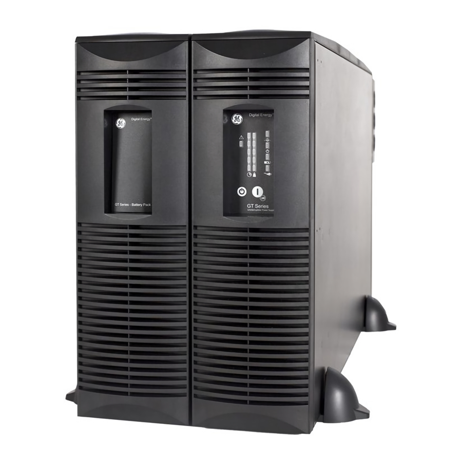
GE Digital Energy Power Quality User manual Digital Energy™ Uninterruptible Power Supply GT Series UPS 6 - 10 kVA imagination at work... - Page 2 User manual GT Series - Uninterruptible Power Supply 6 - 10 kVA We thank you for selecting a General Electric Digital Energy™ GT Series Uninterruptible Power Supply. Please read these instructions carefully before installation and start-up of the GT Series UPS. Keep this manual in a safe place for future reference. Model: GT Series 6 - 10 kVA / Series 1 Date of issue:...
-
Page 3: Table Of Contents
Contents Important safety instructions ..................4 Save these instructions........................4 Safety rules ...............................4 Introduction..........................5 Introduction ..............................5 Intended use ............................5 Transport / storage ..........................5 Warranty..............................5 Installation ..........................6 Package contents ..........................6 Installation rules .............................6 Installation procedure .........................7 3.3.1 Rackmount installation – preparations..................7 3.3.2 Vertical installation –... -
Page 4: Important Safety Instructions
‘(GT Series 10kVA)’. While every care has been taken to ensure the completeness and accuracy of this manual, GE accepts no responsibility or liability for any loss or damage resulting from the use of the information contained in this document. -
Page 5: Introduction
INTRODUCTION INTRODUCTION The GE (General Electric) Digital Energy GT Series UPS, a truly on-line uninterruptible power supply, protects your equipment from all forms of power interference, including complete power failures. INTENDED USE • Uninterruptible Power Supplies (UPS) are designed to protect sensitive electronic equipment such as computers and telecommunications equipment from all forms of power interference, including complete power failure. -
Page 6: Installation
INSTALLATION PACKAGE CONTENTS The UPS shipping box contains: The Battery cabinet shipping box contains: • 9 plastic parts • 4 plastic parts • 4 metal parts (rackmount installation see 3.3.1) • 4 metal parts (rackmount installation see 3.3.1) • 1 screws set – 1 display sticker (vertical orientation) •... -
Page 7: Installation Procedure
INSTALLATION PROCEDURE The UPS can be used in a stand alone tower format using the two supporting stands (section 3.3.2), or can be mounted in a 19 inch rack using the two mounting brackets (section 3.3.1). All required items are included in the delivery, except rails –... -
Page 8: Vertical Installation - Preparations
3.3.2 Vertical installation – preparations Place the UPS and matching battery cabinet horizontally on a flat surface. Assemble the plastic support feet and mount them to UPS and battery cabinet bottom (2, fig. 3.3.2.a). Place the cabinets upright and mount the top cover (3, fig. -
Page 9: Connecting The Battery
3.3.3 Connecting the battery The battery pack connects to the UPS in the same way whether the UPS is being used in tower or rackmount format. When used in tower format, the UPS and the battery pack can be mounted together in one set of mounting supports (fig. -
Page 10: Rear Panel
3.3.5 Rear panel Paralleling terminals (see section 3.4.2) ESD (emergency shutdown) (see 4.4.10) Input/output terminals (see section 3.3.6) External battery connector Parallel port DB9 communication port RPO contacts (see 4.4.11) fig. 3.3.5.a SNMP card slot 10. Input circuit breaker: 2 pole, 30A/250Vac – 6kVA 2 pole, 63A/250Vac –... -
Page 11: Standard Installation Procedure
3.3.6 Standard installation procedure NOTE Ensure that the UPS is isolated prior to installation; no live input source may be connected to the UPS during the installation procedure. Open all the input/output switches/breakers on the power distribution and ensure no one is able to close them during this installation step. Remove the terminal cover (fig. -
Page 12: Parallel Operation
PARALLEL OPERATION The paralleling cable delivered with each UPS allows you to connect up to 3 UPS together in a parallel system. NOTE The units connected in parallel must be the same power rating. (i.e. 6 kVA-6kVA not 6kVA-10kVA). 3.4.1 Installation of a parallel system All inputs of the UPS must be supplied from the same phase. -
Page 13: Installing The Parallel Connection
3.4.2 Installing the parallel connection NOTE Ensure that the UPS is isolated prior to installation; no live input source may be connected to the UPS during the installation procedure. Open all the input/output switches/breakers on the power distribution and ensure no one is able to close them during this installation step. 1. -
Page 14: Operation
OPERATION OPERATING PANEL fig. 4.1: operating panel switch / LED main function ‘UPS off’ switch switches the UPS from normal operation to bypass and from bypass or battery to standby. ‘UPS on’ switch switches on the UPS, starts quick battery test (see section 4.5), mutes the buzzer. -
Page 15: Start-Up
START-UP 4.2.1 Start-up of a single unit Ensure all switches and breakers upstream to the UPS are closed. Switch input circuit breaker to position “On” (fig. 4.2.1). Wait 45 seconds to allow the output voltage to stabilise. Press keypad “I” for 1 second. Within few seconds LED ‘operation’... -
Page 16: Use: Status And Alarm Indications
USE: STATUS AND ALARM INDICATIONS status indications the operating mode low priority alarms abnormal operating situations high priority alarms situations in which the actual output voltage of the UPS is no longer guaranteed; immediate action should be taken Situation Indicators on front panel (fig 4.1) 1 - 5 Stand-by (4.4.9) 1 - 5... -
Page 17: On Bypass
4.4.1 On bypass The UPS is equipped with an automatic bypass switch. This switch automatically transfers the load to the mains if the UPS is unable to deliver the demanded output power due to overload or overtemperature. If all 5 load LEDs are illuminated, bypass operation is caused by an overload. -
Page 18: Replace Battery
4.4.6 Replace battery Either the batteries are almost chemically worn out or the battery wiring, including the battery fuse, is faulty. If the batteries are aged, they must be replaced as soon as possible to ensure full protection for your equipment (see section 7.4.1). -
Page 19: Emergency Shutdown (Esd)
4.4.10 Emergency Shutdown (ESD) For safety reasons, an external 'emergency off' device (switch or relay) can be connected to the ESD terminals 1-2 (fig. 4.4.10). fig. 4.4.10 4.4.11 Remote Power Off (RPO) RPO may be created by replacing the link with a switch with the characteristics of a ‘power off’ button (see fig. -
Page 20: Battery Management
BATTERY MANAGEMENT Maximum battery life and reliability are obtained by the following features: • Battery connection test At start-up and every minute the unit performs an automatic test to check that the battery cabling and fuses are properly connected. If the test detects a battery disconnection, the corresponding alarm will be generated (see section 4.4.7). •... -
Page 21: Communication
COMMUNICATION DB9 COMMUNICATION PORT The RS232 port is a plug-in interface port, which enables advanced communication between the UPS and the computer via serial cable (fig. 5.1) and UPS monitoring software. The interface port is already operative in stand-by mode (see section 4.4.9). To change settings of the unit, we strongly recommend to be sure that the unit is in stand-by mode. -
Page 22: Maintenance
Refer to section 4.3.2 for further details. GENERAL The GE Digital Energy GT Series UPS is virtually maintenance free: take care of proper environmental conditions and keep air inlets/outlets free of dust. Please read 3.2. NOTE Apart from battery replacement refer maintenance and service work to qualified and skilled personnel only. -
Page 23: Battery Replacement
7.4.1 Battery replacement Please refer to figure 7.4.1. Battery cabinet is the same for both power ratings, 6000VA and 10000VA. NOTE During battery replacement the UPS will not be able to support the load if a mains failure occurs! It is recommended to switch off the load before disconnecting the DC connector as in section 4.3.2. -
Page 24: Troubleshooting
8 TROUBLESHOOTING Whenever a malfunction occurs, first check external factors (e.g. connections, temperature, humidity or load) to determine whether the problem is caused by the unit itself or by its environment. Subsequently check the thermal circuit breaker: it may be tripped. If so: reset it (see fig. 3.3.5.a/b) and be sure that the UPS is not overloaded. -
Page 25: Specifications
SPECIFICATIONS Model GT6000 GT10000 Ratings Voltage Amperes (VA) with computer type load 6000 10000 Watts (W) with resistive load 4200 7000 Input thermal circuit breaker (A) Internal input fuse 250V, slow (A) 30*2 Input converter AC input voltage : Nominal: 230 V...