Table of Contents
Advertisement
Instructions-Parts
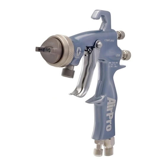
AirPro
Feed Airspray Gun
Conventional, HVLP, and compliant guns for specialty industrial applications.
For professional use only.
100 psi (0.7 MPa, 7 bar) Maximum Air Inlet Pressure
300 psi (2.1 MPa, 21 bar) Maximum Fluid Inlet Pressure
Important Safety Instructions
Read all warnings and instructions in
this manual. Save these instructions.
See page 3 for model information.
™
Pressure
312414J
ENG
ti11094a
ll 2 G
Advertisement
Table of Contents

Related Manuals for Graco AirPro 312414

Summary of Contents for Graco AirPro 312414
- Page 1 Instructions-Parts ™ AirPro Feed Airspray Gun Conventional, HVLP, and compliant guns for specialty industrial applications. For professional use only. 100 psi (0.7 MPa, 7 bar) Maximum Air Inlet Pressure 300 psi (2.1 MPa, 21 bar) Maximum Fluid Inlet Pressure Important Safety Instructions Read all warnings and instructions in this manual.
-
Page 2: Table Of Contents
Related Manuals Contents Related Manuals ......2 Models ........3 General Metal Spray Guns . -
Page 3: Models
Models Conventional Orifice HVLP/Compliant Size Air Pressure in. (mm) Model Series psi (MPa, bar) General Metal Spray Guns 0.020 (0.5) 288726 0.030 (0.8) 288929 0.042 (1.1) 288930 0.055 (1.4) 288931 0.070 (1.8) 288932 0.086 (2.2) 288933 0.110 (2.8) 288934 General Metal with Stainless Steel Tip 0.042 (1.1) 288949 0.055 (1.4) 288950 0.070 (1.8) 288951... -
Page 4: Stain
Models Conventional Orifice HVLP/Compliant Size Air Pressure in. (mm) Model Series psi (MPa, bar) Stain 0.020 (0.5) 288958 0.030 (0.8) 288959 0.040 (1.0) 289109 Waterborne 0.030 (0.8) 288964 0.042 (1.1) 288965 0.055 (1.4) 288966 High Wear 0.059 (1.5) 288973 0.070 (1.8) 288974 0.086 (2.2) 288975 0.110 (2.8) 289982 Adhesives... -
Page 5: Warnings
Warnings The following warnings are for the setup, use, grounding, maintenance, and repair of this equip- ment. The exclamation point symbol alerts you to a general warning and the hazard symbol refers to procedure-specific risk. Refer back to these warnings. Additional, product-specific warnings may be found throughout the body of this manual where applicable. -
Page 6: Gun Selection
Gun Selection PRESSURIZED EQUIPMENT HAZARD Fluid from the gun/dispense valve, leaks, or ruptured components can splash in the eyes or on skin and cause serious injury. • Follow Pressure Relief Procedure in this manual, when you stop spraying and before cleaning, checking, or servicing equipment. •... -
Page 7: Setup
Setup At least one hose must provide a static ground to the gun. Connect Air and Fluid Lines 1. Shut off the air supply. 2. Install a shutoff valve (not supplied) down- stream of the air regulator to shut off gun air. -
Page 8: Adjust Spray Pattern
Setup Adjust Spray Pattern 1. Rotate the air cap to achieve desired spray pattern. See F . 2. ti4839a 2. To achieve full fan pattern, open the air control valve by turning the knob fully coun- terclockwise. See F . 3. 3. -
Page 9: Operation
Operation Pressure Relief Procedure Trapped air can cause the pump to cycle unexpectedly, which could result in serious injury from splashing or moving parts. 1. Turn off air and fluid supply. 2. Hold a metal part of the gun firmly to a grounded metal pail. -
Page 10: Daily Gun Maintenance
Daily Gun Maintenance Daily Gun Maintenance Follow Pressure Relief Procedure, page 9, when you stop spraying and before cleaning, checking, servicing, or transporting equip- ment. Read Warnings, page 5. General Tasks • Frequently lubricate the gun moving parts with a drop of non-silicone oil. •... -
Page 11: Clean Gun
Clean Gun CAUTION • Do not submerge gun in solvent. Solvent dissolves lubricant, dries out packings, and clogs air passages. • Do not use metal tools to clean air cap holes as this may scratch them and distort the spray pattern. •... -
Page 12: Troubleshooting
Troubleshooting Troubleshooting Problem Spray Pattern Right Spray Pattern Wrong Heavy top or bottom Spray Pattern Wrong Split pattern Spray Pattern Wrong Cause Normal pattern. Dirty or damaged air cap or fluid nozzle. Pressure too high for viscosity of material being sprayed. Dirty or distorted air horn holes. - Page 13 Problem Gun spitting. Will not spray. Excessive air blowing back. Excessive air leak behind trigger. Gun fluid pressure is too high with gun triggered (cannot achieve desired flow rate). Using a low fluid pressure set- ting, the fluid flow is too high, making it necessary to restrict needle travel to reduce fluid flow.
-
Page 14: Repair
Repair Repair Follow Pressure Relief Procedure, page 9. See Parts, page 16, for callout references. Disassembly 1. Unscrew retaining ring (14) to remove air cap (13b). Check o-rings (13a and 13c) and replace if necessary. 2. Trigger gun while unscrewing nozzle (11) to prevent needle damage. -
Page 15: Reassembly
Reassembly 1. Install air control valve assembly (5) with valve turned fully counterclockwise to out- ermost position. Torque to 85-90 in-lb (9.6-10.2 N•m). 2. Install air inlet valve assembly (27) with valve turned fully counterclockwise to out- ermost position. Torque to 205-215 in-lb (23.2-24.3 N•m). -
Page 16: Parts
Parts Parts Pull trigger before installing nozzle (11). Insert spreader (15) with tapered end facing rear of gun. Insert u-cup (16) with open end facing front of gun. Apply lubricant. Apply low strength thread retainer. Apply high-strength thread retainer. Torque to 85-90 in-lbs (9.6-10.2 N•m). Torque to 15-20 in-lbs (1.7-2.2 N•m). - Page 17 Ref. Part Description 1❖ 289016 BODY, gun 2‡❖ GASKET, fluid inlet 3‡❖ FITTING, fluid inlet 289796 VALVE, air control assembly 6★* 289038 VALVE, air, assembly 1 289052 NUT, air valve, u-cup assembly 289097 VALVE, fluid control NEEDLE, assembly p. 20-22 (includes 9a-9c) NUT, needle NEEDLE...
- Page 18 Parts 312414J...
-
Page 19: Accessories
Accessories Repair Kits Part No. Description 289455 Needle Packing Repair Kit 289399 Gun Repair Kit 289791 Air Cap Seal Kit 289143 Trigger Repair Kit 289407 Air Valve Repair Kit 289079 Retaining Ring Kit 24C269 Fluid Inlet Fitting Kit 24C310 Nozzle O-Ring Kit, 5-pack 289016 Gun Body Kit 288986... -
Page 20: Repair Kits
Repair Kits Repair Kits Nozzle Size Model Spray Type in. (mm) General Metal Spray Guns 288726 Conventional 0.020 (0.5) 288929 Conventional 0.030 (0.8) 288930 Conventional 0.042 (1.1) 288931 Conventional 0.055 (1.4) 288932 Conventional 0.070 (1.8) 288933 Conventional 0.086 (2.2) 288934 Conventional 0.110 (2.8) 288935... - Page 21 Nozzle Size Model Spray Type in. (mm) Automotive 288929 Conventional 0.030 (0.8) 288930 Conventional 0.042 (1.1) 24D472* Conventional 0.042 (1.1) 288931 Conventional 0.055 (1.4) 289034 HVLP 0.040 (1.0) 289035 HVLP 0.047 (1.2) 289541 HVLP 0.055 (1.4) 289036 Compliant 0.040 (1.0) 289037 Compliant 0.047 (1.2)
- Page 22 Repair Kits Nozzle Size Model Spray Type in. (mm) Waterborne 288964 Conventional 0.030 (0.8) 288965 Conventional 0.042 (1.1) 288966 Conventional 0.055 (1.4) 288967 HVLP 0.030 (0.8) 288968 HVLP 0.042 (1.1) 288969 HVLP 0.055 (1.4) 288970 Compliant 0.030 (0.8) 288971 Compliant 0.042 (1.1) 288972 Compliant...
-
Page 23: Technical Data
Technical Data Maximum Air Inlet Pressure ......100 psi (0.7 MPa, 7 bar) Maximum Fluid Inlet Pressure ......300 psi (2.1 MPa, 21 bar) Maximum HVLP*/Compliant Inbound Air Pressure . -
Page 24: Graco Standard Warranty
Graco Standard Warranty Graco warrants all equipment referenced in this document which is manufactured by Graco and bearing its name to be free from defects in material and workmanship on the date of sale to the original purchaser for use. With the exception of any special, extended, or limited warranty published by Graco, Graco will, for a period of twelve months from the date of sale, repair or replace any part of the equipment determined by Graco to be defective.