Table of Contents
Advertisement
WIRELESS 915 MHz WEATHER STATION
INTRODUCTION
Congratulations on purchasing this weather station with wireless 915 MHz transmission of outdoor
temperature/humidity, and display of indoor temperature/humidity and air pressure. It also
functions as a normal clock with calendar display and alarm setting. In addition, weather forecast,
sunrise/ sunset time as well as the moon phase are shown. This innovative product is ideal for use
in the home or office.
FEATURES
The weather station
LCD
display
WS-9257U-IT
Instruction Manual
1
Function
keys
Hanging
hole
Battery
compartment
Foldout
stand
Advertisement
Table of Contents

Related Manuals for La Crosse Technology WS-9257U-IT


Summary of Contents for La Crosse Technology WS-9257U-IT
- Page 1 WIRELESS 915 MHz WEATHER STATION WS-9257U-IT Instruction Manual INTRODUCTION Congratulations on purchasing this weather station with wireless 915 MHz transmission of outdoor temperature/humidity, and display of indoor temperature/humidity and air pressure. It also functions as a normal clock with calendar display and alarm setting. In addition, weather forecast, sunrise/ sunset time as well as the moon phase are shown.
- Page 2 12 hour time display (seconds displayed by pressing the SUN key) Weekday, date and month display (year only in setting mode) Daylight saving time (DST) function selectable Daily alarm function Weather forecast with weather tendency indicator ...
- Page 3 The outdoor thermo-hygro transmitter Remote transmission of outdoor temperature and humidity to weather station by 915 MHz Alternately display the outdoor temperature and humidity on LCD Wall mounting case Mounting at a sheltered place. Avoid direct rain and sunshine INITIAL SET UP DO NOT MIX OLD AND NEW BATTERIES.
- Page 4 within 80 seconds, remove the batteries from both units for 2 minutes and start again from step 1. Allow the weather station and the transmitter to remain 5-10 feet apart for 15 minutes after set up to establish a strong connection. To ensure sufficient 915 MHz transmission after set up, the distance between the transmitter mounted outside and the weather station inside should not exceed 330 feet (100 meters) distance (open air, no obstructions).
-
Page 5: Battery Change
HOW TO INSTALL AND REPLACE BATTERIES IN THE WEATHER STATION The weather station uses 2 x C, IEC LR14, 1.5V batteries. To install and replace the batteries, please follow the steps below: Remove the cover at the back of the weather station. Insert batteries, observing the correct polarity (see marking). - Page 6 SUN key ALARM key SET key + key MIN/MAX key SET key Press and hold for 2 seconds to enter manual setting modes: LCD contrast, DST ON/OFF, manual time setting, calendar and relative air pressure value To stop the alarm sound ...
-
Page 7: Lcd Screen
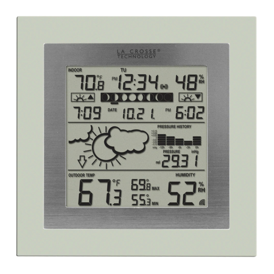
Press and hold the key for 2 seconds to reset ALL indoor/outdoor minimum/maximum temperature recordings to current readings To stop the alarm sound ALARM key To activate/deactivate the alarm and display alarm time Press and hold for 2 seconds to enter the alarm setting mode ... - Page 8 Weekday Alarm icon Time Indoor temperature Indoor in °F humidity display in RH% Moon phase indicator Sunset time Sunrise time Air pressure Weather history bar forecast icon graph Weather Relative and tendency absolute air indicator pressure Low battery display indicator Outdoor (weather humidity...
-
Page 9: Manual Settings
whether the last reception was successful (icon on) or not (icon off). On the other hand, the flashing of the icon shows that a reception is being done now. MANUAL SETTINGS The following settings can be changed when pressing the SET key: ... -
Page 10: Daylight Saving Time Setting
Press the SET key to confirm and enter the “Daylight Saving Time setting” or exit the setting mode by pressing the ALARM key or SUN key. DAYLIGHT SAVING TIME SETTING Flashing The daylight saving time (DST) function can be set ON/OFF. Default setting is “ON”: “ON”... -
Page 11: Calendar Setting
To set the clock: The hour digit will start flashing. Use the + key to increase or MIN/MAX key to decrease the value. Keep holding the key allows the value to advance faster. Confirm with the SET key and enter minute setting. The minute will be flashing. - Page 12 The month digit will be flashing. Use the + key to increase or MIN/MAX key to decrease the value. Press the SET key to enter date setting. Keep holding the key allows the value to advance faster. The date digit will be flashing. Use the + key to increase or MIN/MAX key to decrease the value.
- Page 13 LOCATION SETTNG FOR SUNRISE/SUNSET TIME The weather station will automatically update the sunrise, sunset and sun duration time at 00:00, based on the city location, the date, time and DST settings. Country code (flashing) Press and hold the SUN key for 2 seconds to enter the Location setting mode. The short form of country name will start flashing.
- Page 14 To select a US state and city: Once “USA” has been selected, press the SUN key to enter the state setting. The state code (2 letters abbr. ) will start flashing. Press the + or MIN/MAX key to select the state. After the state has been selected, press the SUN key to enter the city setting.
- Page 15 Sunrise icon Sunset icon Sunrise time of Sun duration Sunset time of selected city (hours : minutes) selected city Press the SUN key twice to go back to normal date display. User can exit the setting mode by pressing the SET key or ALARM key without saving the changes.
- Page 16 To select a Canadian city: Once “CAN” has been selected, press the SUN key to enter the city setting. The city code (3 letters abbr.) will start flashing. Press the + or MIN/MAX key to select the city. Confirm with the SUN key. The city’s sunrise, sun duration and sunset time will be displayed in a few Country code (flashing) seconds.
-
Page 17: Alarm Setting
Sunset icon Sunrise icon Sunrise time of selected city Sunset time of Sun duration selected city (hours : minutes) Press the SUN key twice to go back to normal date display. User can exit the setting mode by pressing the SET key or ALARM key without saving the changes. -
Page 18: The Moon Phase
The hour digit will be flashing. Press the + key or MIN/MAX key to adjust the hour. Press ALARM key once and minute digit will be flashing. Press + key or MIN/MAX key to set the minute. Press ALARM key once to confirm the setting, or exit the setting mode by pressing the SET key or SUN key. -
Page 19: Weather Forecasting Icons
Full Last Waxing First Waxing Waning Waning Moon Crescent Quarter Gibbous Gibbous Quarter Crescent Moon A bar segment indicates the current moon phase WEATHER FORECASTING ICONS Weather icons can be displayed in any of the following combinations: Sun with cloud Cloud with rain For every sudden or significant change in the air pressure, the weather icons will update accordingly to represent the change in weather. -
Page 20: Weather Tendency Indicator
Note: After setting up, readings for weather forecasts should be disregarded for the next 12-24 hours. This will allow sufficient time for the Weather station to collect air pressure data at a constant altitude and therefore result in a more accurate forecast. Common to weather forecasting, absolute accuracy cannot be guaranteed. -
Page 21: Air Pressure History (Electronic Barometer With Barometric Pressure Trend)
Note: Once the weather tendency indicator has registered a change in air pressure, it will remain permanently visualized on the LCD. AIR PRESSURE HISTORY (ELECTRONIC BAROMETER WITH BAROMETRIC PRESSURE TREND) The right side of the second section on the LCD shows the air pressure history bar graph. Air pressure unit in inHg Air pressure trend over the last 12 hours The bar graph indicates the air pressure history trend over the past 12 hours in 7... - Page 22 Note: For accurate barometric pressure trends, the weather station should operate at the same altitude for recordings (i.e. it should not be moved from the ground to the second floor of the house). When the unit is moved to a new location, discard readings for the next 12 hours. DISPLAY OF INDOOR TEMPERATURE/HUMIDITY DATA The indoor temperature and humidity are measured automatically and displayed on the first section of the LCD.
- Page 23 DISPLAY OF INDOOR/OUTDOOR MAXIMUM AND MINIMUM RECORDS Press the MIN/MAX key several times to view the MIN/MAX indoor temperature, and MIN/MAX outdoor temperature sequentially. Date and time of recordings will be shown for outdoor temperature data. Recorded MIN/MAX outdoor temperature time Recorded MIN/MAX outdoor temperature date...
-
Page 24: Low Battery Indicators
LOW BATTERY INDICATORS Low battery indicator will show on the LCD when the batteries of weather station or transmitter require changing. THERMO-HYGRO TRANSMITTER The reception distance of the thermo-hygro transmitter may be affected by the temperature. At cold temperatures the transmitting distance may be decreased. Please bear this in mind when placing the transmitter. - Page 25 reset. Should this happen accidentally then reset all units (see Setting up above) otherwise transmission problems may occur. The transmission range is about 330 feet / 100 meters from the transmitter to the weather station (in open space). However, this depends on the surrounding environment and interference levels. If no reception is possible despite the observation of these factors, all system units have to be reset (see Setting up).
- Page 26 Note: Always ensures that the unit locks onto the screw head before releasing. POSITIONING THE THERMO-HYGRO TRANSMITTER: The thermo-hygro transmitter can be placed on any flat surface or wall mount using the bracket which doubles as a stand or wall mount base. To wall mount: Secure the bracket onto a desired wall using the screws and plastic anchors.
-
Page 27: Care And Maintenance
CARE AND MAINTENANCE: Extreme temperatures, vibration and shock should be avoided as these may cause damage to the unit and give inaccurate forecasts and readings. When cleaning the display and casings, use a soft damp cloth only. Do not use solvents or scouring agents as they may mark the LCD and casings. -
Page 28: Warranty Information
La Crosse Technology, Ltd for problem determination and service procedures. Warranty service can only be performed by a La Crosse Technology, Ltd authorized service center. The original dated bill of sale must be presented upon request as proof of purchase to La Crosse Technology, Ltd or La Crosse Technology, Ltd’s authorized service... - Page 29 La Crosse Technology, Ltd will repair or replace this product, at our option and at no charge as stipulated herein, with new or reconditioned parts or products if found to be defective during the limited warranty period specified above. All replaced parts and products become the property of La Crosse Technology, Ltd and must be returned to La Crosse Technology, Ltd.
- Page 30 LA CROSSE TECHNOLOGY, LTD WILL NOT ASSUME LIABILITY FOR INCIDENTAL, CONSEQUENTIAL, PUNITIVE, OR OTHER SIMILAR DAMAGES ASSOCIATED WITH THE OPERATION OR MALFUNCTION OF THIS PRODUCT. THIS PRODUCT IS NOT TO BE USED FOR MEDICAL PURPOSES OR FOR PUBLIC INFORMATION.
- Page 31 Product Info and Support: Product Registration: www.lacrossetechnology.com/9257 www.lacrossetechnology.com/support/register The complete instruction manual is available at: www.lacrossetechnology.com/9257 Le manuel d'instruction complet est disponible sur: www.lacrossetechnology.com/9257 El manual de instrucciones completo está disponible en: www.lacrossetechnology.com/9257...
- Page 32 List of Country / State / City Codes USA = UNITED STATES OF DISTRIC OF COLUMBIA (DC) AMERICA WASHINGTON = DCA ALABAMA (AL) FLORIDA (FL) MONTGOMERY = MGM JACKSONVILLE = JAX MOBILE = MOB MIAMI = MIA ARKANSAS (AR) ORLANDO = ORL LITTLE ROCK = LIT TALLAHASSEE = TLH ARIZONA (AZ)
- Page 33 INDIANA (IN) INTERNATIONAL FALLS = INL EVANSVILLE = EVV MISSOURI (MO) INDIANAPOLIS = IND JEFFERSON CITY = JEF KANSAS (KS) MISSISSIPI (MS) DODGE CITY = DDC JACKSON = JAN WICHITA = K32 MONTANA (MT) TOPEKA = TOP BILLINGS= BIL KENTUCKY (KY) HELENA = HLN LEXINGTON = LEX NORTH CAROLINA (NC)
- Page 34 ALBUQUERQUE = ABQ CHARLSTON = CHS NEVADA (NV) COLUMBIA = CUB LAS VEGAS = LAS SOUTH DAKOTA (SD) RENO = RNO SIOUX FALLS = FSD NEW YORK (NY) RAPID CITY = RAP BUFFALO = BUF TENNESSEE (TN) NEW YORK CITY = JFK NASHVILLE = BNA SYRACUSE = SYR KNOXVILLE = DKX...
- Page 35 NORFOLK = ORF GREEN BAY = GRB VERMONT (VT) LA CROSSE = LSE BURLINGTON = BTV WEST VIRGINIA (WV) WASHINGTON (WA) CHARLESTON = CRW SEATTLE = SEA WYOMING (WY) SPOKANE = SFF CASPER = CPR WISCONSIN (WI) CA = CANADA...
- Page 36 FCC ID: OMO-M-15 (transmitter) FCC DISCLAIMER RF Exposure mobile: The internal / external antennas used for this mobile transmitter must provide a separation distance of at least 20 cm (8 inches) from all persons and must not be co-located or operating in conjunction with any other antenna or transmitter."...
- Page 37 Reorient or relocate the receiving antenna. Increase the separation between the equipment and receiver. Connect the equipment into an outlet on a circuit different from that to which the receiver is connected. Consult the dealer or an experienced radio/TV technician for help. All rights reserved.