
Related Manuals for Planet ICA-HM126


Summary of Contents for Planet ICA-HM126
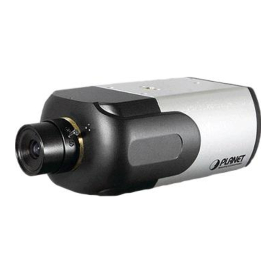
- Page 1 H.264 Full-HD IP Camera ICA-HM126 / ICA-HM126R ICA-HM131 / ICA-HM131R User’s manual Version 1.0.0 - 1 -...
-
Page 2: Ce Mark Warning
Copyright Copyright (C) 2010 PLANET Technology Corp. All rights reserved. The products and programs described in this User’s Manual are licensed products of PLANET Technology, This User’s Manual contains proprietary information protected by copyright, and this User’s Manual and all accompanying hardware, software, and documentation are copyrighted. - Page 3 Revision User’s Manual for PLANET H.264 Full-HD Box IP Camera Model: ICA-HM126 / ICA-HM126R / ICA-HM131 / ICA-HM131R Rev: 1.0.0 (2010, June) Part No. EM-ICAHM126_131 Series - 3 -...
-
Page 4: Table Of Contents
Chapter 1 Introduction ......................6 Overview............................... 6 Package Content ............................7 Physical Details ............................7 Top View – ICA-HM126 Series ......................7 Rear View – ICA-HM126 Series......................8 Top View – ICA-HM131 Series ......................9 Side View – ICA-HM131 Series ......................10 Chapter 2 Preparations for IP Camera Setup .............. - Page 5 4.3.12 View User Information....................38 4.3.13 View Parameters......................40 4.3.14 Factory Default........................ 40 4.3.15 Software Version ......................41 4.3.16 Software Upgrade......................41 4.4 Video and Audio Streaming Settings ....................44 4.4.1 Video Resolution and Rotate Type .................. 44 4.4.2 Video Compression ......................46 4.4.3 Video OCX Protocol .......................
-
Page 6: Chapter 1 Introduction
Users can build a more advanced security system by connecting external sensors or alarm to DI / DO ports of the ICA-HM126/126R. The IP Camera can be managed by PLANET Cam Viewer Plus, the professional central management software for multi-camera video surveillance application, to provide monitoring, recording and event management functions. -
Page 7: Package Content
• Supports Micro SD card storage • External I/O trigger for various surveillance applications (ICA-HM126 Series) • Provides 10 Motion Detection areas can monitor any suspicious movement in specific areas • Easy configuration and management via Windows-Based utility or web interface •... -
Page 8: Rear View - Ica-Hm126 Series
Rear View – ICA-HM126 Series 5. Auto Iris 1. Video Out Connector Connector 6. Line In / 2. DI / DO Line Out Connector 7. Mirco SD 3. Reset Card slot Button 4. Power 8. RJ-45 Connector LAN Socket Side View of ICA-HM126/126R... -
Page 9: Top View - Ica-Hm131 Series
Top View – ICA-HM131 Series 4. Tilt Fixed 1. Lens Screw 2. Reset Button 5. Microphone 3. Focus Fixed Screw Top View of ICA-HM131/131R Item Description Lens Rotate the lens right/left to adjust focus Reset Button Restore to default setting, press the button with a proper tool Loosen the screw to adjust the lens Focus Fixed Screw Tilt Fixed Screw... -
Page 10: Side View - Ica-Hm131 Series
Side View – ICA-HM131 Series 2. RJ-45 LAN Socket 1. Micro-SD Card slot Side View of ICA-HM131/131R Item Description User can insert a micro SD card into this slot for event recording. Micro-SD Card slot The LAN socket is a RJ-45 connector for connections to 10/100Base-TX Fast Ethernet cabling. -
Page 11: Chapter 2 Preparations For Ip Camera Setup
2.2 Installation Please follow the instructions below to complete IP Camera installation. 2.2.1 ICA-HM126 Series Installation Step 1. Lens Mounting: C/CS Mount Lens Model If use CS-Mount lens, after removing the camera’s plastic cover, users need to mount the C/CS mount adapter to the camera. - Page 12 NOTE: The C/CS Mount Adapter isn’t attached in product package. Step 2. Plug an Ethernet cable into the Camera Connect an Ethernet cable to the LAN socket located on the IP Camera’s bottom and attach it to the network. Step 3. Connect the external power supply to Camera Connect the attached power adapter to the DC power jack of the IP Camera.
-
Page 13: Ica-Hm131 Series Installation
Injector Hub for the network that already existed with Ethernet Switches or POE Switch all can be deployed 2.3 Alarm Application (ICA-HM126 Series) The camera equips one relayalarm input and one relay output for alarm application. Refer to alarm pin definition below to connect alarm devices to the IP Camera if needed. -
Page 14: Chapter 3 Accessing Camera
Chapter 3 Accessing Camera For initial access to the IP Camera, users can search the camera through the installer program: DeviceSearch.exe, which can be found in “DeviceSearch” folder in the supplied CD. 3.1 Device Search Software Setup Step 1: Double click on the program Planet Device Search.exe (see the icon below); its window will appear as shown below. -
Page 15: Device Search
3.2 Device Search Step 3: Click “Device Search” again, and all the finding IP devices will be listed in the page, as shown in the figure below. The IP Camera’s default IP address is: 192.168.0.20. Step 4: Double click or right click and select “Browse” to access the camera directly via web browser. Step 5: Then the prompt window of request for entering default username and password (as shown below) will appear for logging in to the IP Camera. -
Page 16: Example Of Changing Ip Camera's Network Property
The default login ID and password for the Administrator are: Login ID Password null (without password) admin NOTE: ID and password are case sensitive. NOTE: It is strongly advised that administrator’s password be altered for the security concerns. Refer to section 4.3.2 Security for further details. -
Page 17: Installing Dc Viewer Software Online
Step 3: Click “OK” on the Note of setting change. Wait for one minute to re-search the IP Camera. Step 4: Click the “Device Search” button to search all the devices. Then select the IP Camera with the correct MAC address. Double click on the IP Camera, and the login window will come out. Step 5: Enter User name and Password to access the IP Camera. -
Page 18: Administrator / User Privileges
Click “Finish” to close the DC Viewer window when download is finished. Once login to the IP Camera, users will see the Home page as shown below: NOTE: The “talk” button below the screen only displays in ICA-HM126 Series IP Camera. 3.5 Administrator / User Privileges “Administrator”... -
Page 19: Lens Adjustment
3.6 Lens Adjustment The image displays on the Home page when successfully accessing to the IP Camera. Adjust the camera’s focus to produce a clear image. Please refer to the procedure below. ICA-HM131 Series Lens Adjustment Step 1: Unscrew the IP Camera’s cover. Step 2: Loosen the focus fixed screw, and rotate the lens counter-/clockwise to adjust focus;... -
Page 20: Chapter 4 Configuration & Operation
Chapter 4 Configuration & Operation The IP Camera is provided with a user-friendly browser-based configuration interface, and a free bundled CMS (Central Management System) for record and playback video. In this chapter, information about main page introduction, system related settings and camera settings will be described in detail. 4.1 Browser-based Viewer Introduction The figure below shows the Home page of the IP Camera’s Viewer Window. -
Page 21: Home Page
Streaming setting The administrator can modify video resolution and rotate type and select audio compression mode in this page. Camera setting Users can adjust various camera parameters, including <Exposure>, <White Balance>, <Brightness>, <Sharpness>, <Contrast> and <Digital Zoom>. Logout Click on the tab to re-login the IP Camera with another username and password. 4.2 Home Page In the Home page, there are several function buttons right down the displayed image. -
Page 22: System Related Settings
NOTE: This function is only available for ICA-HM126 Series IP Camera. Snapshot Press the button, and the JPEG snapshots will automatically be saved in the appointed place. The default place of saving snapshots is: C:\. 4.3 System Related Settings The figure below shows all categories under the “System” tab. Each category in the left column will be explained in the following sections. -
Page 23: Security
Host Name The name is for camera identification. If Motion Detection function is enabled and is set to send alarm message by Mail/FTP, the host name entered here will display in the alarm message. Time Zone Select the time zone you are in from the drop-down menu. Sync with Computer Time Select the item, and video date and time display will synchronize with the PC’s. - Page 24 Root password Change the administrator’s password by inputting the new password in both text boxes. The input characters/numbers will be displayed as dots for security purposes. After clicking <Save>, the web browser will ask the Administrator for the new password for access. The maximum length of the password is 14 digits.
- Page 25 NOTE: The ICA-HM131 Series do not have the Talk function. Manage User Delete user To delete a user, pull down the user list, and select the user name you wish to delete. Then click <Delete> to remove it. Edit user Pull down the user list and select a user name.
-
Page 26: Network
4.3.3 Network Click <Network> in the left column, and the page will display as shown below. Users can choose to use fixed IP address or dynamic (DHCP) IP address. The following is descriptions for the two ways of setting IP address. Get IP address automatically (DHCP) The camera’s default setting is “Use fixed IP address”. - Page 27 When using static IP address to login to the IP Camera, users can access it either through “DeviceSearch” software (see Chapter 3. Accessing Camera) or input the IP address in the URL bar and press “Enter”. General • IP address This is necessary for network identification.
-
Page 28: Ddns
• Web Server port The default web server port is 80. Once the port is changed, the user must be notified the change for the connection to be successful. For instance, when the Administrator changes the HTTP port of the IP Camera whose IP address is 192.168.0.100 from 80 to 8080, the user must type in the web browser “http://192.168.0.100:8080”... -
Page 29: Mail
Provider Select one DDNS host from the provider list. Host name Enter the registered domain name in the field. Username/E-mail Enter the username or e-mail required by the DDNS provider for authentication. Password/Key Enter the password or key required by the DDNS provider for authentication. 4.3.5 Mail The Administrator can send an e-mail via Simple Mail Transfer Protocol (SMTP) when motion is detected. -
Page 30: Ftp
Press “Save” when finished. 4.3.7 Application (ICA-HM126 Series) The ICA-HM126 Series IP Camera equips one alarm input and one relay output for cooperating with alarm system to catch events’ images. The alarm configuration page is also shown below. - Page 31 Alarm Switch The Administrator can enable or disable the alarm function. Alarm Type Select an alarm type, “Normal close” or “Normal open,” that corresponds with the alarm application. Alarm Output Define alarm output signal “high” or “low” as the normal alarm output status according to the current alarm application.
- Page 32 • Upload Image by E-Mail Select this item, and the Administrator can assign an e-mail address and configure various parameters as shown in the figure below. When the alarm is triggered, event images will be sent to the appointed e-mail address. NOTE: Make sure SMTP or FTP configuration has been completed.
-
Page 33: Motion Detection
File Name: imageXX.jpg X: Sequence Number The file name suffix will end at the number being set. For example, if the setting is up to “10,” the file name will start from 00, end at 10, and then start all over again. •... - Page 34 selected Window, and click on the “delete” button. If Motion Detection function is activated, the pop-off window (Motion) with indication of motion will be shown. When motion is detected, the signals will be displayed on the Motion window as shown below. Detailed settings of Motion Detection are described as follows: Motion Detection You will be able to turn on/off Motion Detection in System section.
- Page 35 • Time interval (sec) [0-7200]: The default interval is 10. The value is the interval between each detected motion. Users could adjust the parameter and level of Motion Detection Settings. • Sampling pixel interval [1-100]: Default value: 10 • Detection level [1-100]: Default value: 10 •...
-
Page 36: Snapshot
• Upload Image by E-Mail Select this item, and the Administrator can assign an e-mail address and configure various parameters as shown in the figure below. When motion is detected, event images will be sent to the appointed e-mail address. NOTE: Make sure SMTP or FTP configuration has been completed. -
Page 37: Iris Adjustment (Ica-Hm126 Series)
4.3.10 Iris adjustment (ICA-HM126 Series) If there is Auto Iris Lens connected with ICA-HM126 Series, system will automatically adjust different Auto Iris Lens. Please connect the Auto Iris Lens with IP Camera properly at first, then according to the steps to carry out the adjustment works. -
Page 38: View User Information
4.3.12 View User Information The Administrator can view each added user’s login information and privileges (see 4.3.2 Security). View User Login Information All the users in the network will be listed in the “User information” zone, as shown below. As the figure below shows: User: 4321 It indicates that one user’s login username is: User and the password is: 4321. - Page 39 1:1:0:1= I/O access: Camera control: Talk: Listen (see 4.3.2 Security) Therefore, it denotes the user is granted privileges of I/O access, Camera control and Listen. NOTE: The Talk option is only available for ICA-HM126 Series IP Camera. - 39 -...
-
Page 40: View Parameters
4.3.13 View Parameters Click on this item to view the entire system’s parameter setting. 4.3.14 Factory Default The factory default setting page is shown as below. Follow the instructions to reset the IP Camera to factory default setting if needed. - 40 -... -
Page 41: Software Version
Set Default Click on the “Set Default” button to recall the factory default settings. Then the system will restart in 30 seconds. NOTE: The IP address will be restored to default. Reboot Click on the “Reboot” button, and the system will restart without changing current settings. 4.3.15 Software Version The current software version is displayed in the software version page, which is shown as the figure below. - Page 42 NOTE: Make sure the upgrade software file is available before carrying out software upgrade. The procedure of software upgrade is like the following: Step 1: Click “Browse” and select the binary file to be uploaded, ex.Userland.jffs2. NOTE: Do not change the upgrade file name, or the system will fail to find the file. - 42 -...
- Page 43 Step 2: Pull down the upgrade binary file list and select the file you want to upgrade; in this case, select “userland.jffs2.” Step 3: Press “Upgrade”. The system will first check whether the upgrade file exists or not, and then begin to upload the upgrade file.
-
Page 44: Video And Audio Streaming Settings
MJPEG 1080p (15fps) ; (ICA-HM126, ICA-HM131) • H.264 1080p (15fps) ; (ICA-HM126, ICA-HM131) • MJPEG 1080p (30fps); (ICA-HM126R, ICA-HM131R) • H.264 1080p (30fps); (ICA-HM126R, ICA-HM131R) • MJPEG 720p (30fps) + BNC Output; (ICA-HM126 Series) Click “Save” to confirm the setting. - 44 -... - Page 45 Video Rotate Type Users can change video display type if necessary. Selectable video rotate types include Normal, Flip, Mirror and 180 degree. Differences among these types are illustrated as below. Suppose the displayed image of IP Camera is shown as the figure below. To rotate the image, users can select “Flip”, for instance.
-
Page 46: Video Compression
4.4.2 Video Compression Users can select a proper MJPEG/H.264 compression mode in the video compression page (see the figure below), depending on the application. MJPEG compression settings include: • high compression, low bitrate, low quality • middle compression, default • low compression, high bitrate, high quality H.264 compression settings include: •... -
Page 47: Video Frame Skip
Video OCX protocol setting options include: • RTP over UDP / RTP over RTSP(TCP) / RTSP over HTTP / MJPEG over HTTP Select a mode according to your data delivery requirements. • Multicast Mode Enter all required data, including multicast IP address, H.264 video port, MJPEG video port, audio port and TTL into each blank. -
Page 48: Audio Mode And Bit Rate Settings
In the Full-duplex mode, the local and remote sites can communicate with each other simultaneously, i.e. both sites can speak and be heard at the same time. NOTE: This option is only available in the ICA-HM126 Series IP Camera. •... -
Page 49: Camera Settings
• Simplex (Listen only) In the Listen only Simplex mode, the local/remote site can only listen to the other site. • Disable Select the item to turn off the audio transmission function. Bit Rate Selectable audio transmission bit rate include 16 kbps (G.726), 24 kbps (G.726), 32 kbps (G.726), 40 kbps (G.726), uLAW (G.711) and ALAW (G.711). -
Page 50: Exposure Setting
4.5.1 Exposure Setting The Exposure pull-down menu is shown as follows: The exposure is the amount of light received by the image sensor and is determined by the width of lens diaphragm opening (iris adjustment), the amount of exposure by the sensor (shutter speed) and other exposure parameters. -
Page 51: Brightness Setting
Light Sources Color Temperature in K Cloudy Sky 6,000 to 8,000 Noon Sun and Clear Sky 6,500 Household Lighting 2,500 to 3,000 75-watt Bulb 2,820 Candle Flame 1,200 to 1,500 Auto Mode In this mode, white balance works within its color temperature range and calculates the best-fit white balance. -
Page 52: Saturation
4.5.6 Saturation Users can adjust the saturation of color components in an image through the Saturation function, which is adjustable from -6 ~ +19. 4.5.7 Hue Users can adjust the hue of color components in an image through the Hue function, which is adjustable from -12 ~ +13. -
Page 53: Appendix A: Ip Camera Specifications
Appendix A: IP Camera Specifications Product ICA-HM126 ICA-HM126R Video Specification Image Sensor 1/2.7” Progressive CMOS Lens Focal Length 4.0 mm, F1.5, CS mount type Minimum illumination 0.2 Lux @ F1.2 Video Resolution H.264 1080p / 720p M-JPEG 1080p / 720p / D1 / CIF... - Page 54 Product ICA-HM131 ICA-HM131R Video Specification Image Sensor 1/2.7” Progressive CMOS Lens Focal Length 4.0 mm, F1.5 Minimum illumination 0.2 Lux @ F1.2 View Angle (Horizontal / Vertical) 66 / 52 Degree Scan Method Progressive Video Encoder H.264 / M-JPEG Rate Control VBR (Variable Bit Rate) Video Resolution H.264 1080p / 720p...
-
Page 55: Appendix B: Internet Security Settings
Appendix B: Internet Security Settings If ActiveX control installation is blocked, please either set Internet security level to default or change ActiveX controls and plug-ins settings. Internet Security Level: Default Step 1: Start the Internet Explorer (IE). Step 2: Select <Tools> from the main menu of the browser. Then Click <Internet Options>. Step 3: Click the <Security>... - Page 56 ActiveX Controls and Plug-ins Settings Step 1~3: Refer to the previous section above. Step 4: Down the page, press “Custom Level” (see the figure below) to change ActiveX controls and plug-ins settings. The Security Settings screen is displayed as below: - 56 -...
- Page 57 Step 5: Under “ActiveX controls and plug-ins”, set ALL items (as listed below) to <Enable> or <Prompt>. ActiveX controls and plug-ins settings: 1. Automatic prompting for ActiveX controls 2. Binary and scrip behaviors 3. Download signed ActiveX controls 4. Download using ActiveX controls 5.
-
Page 58: Appendix C: Dc Viewer Download Procedure
Appendix C: DC Viewer Download Procedure The procedure of DC Viewer software download is specified as follows. Step 1: In the DC Viewer installation page, click “Next” for starting installing. Step 2: Setup starts. Please wait for a while until the loading bar runs out. - 58 -... - Page 59 Step 3: Click “Finish” to close the DC Viewer installation page. Then, the IP Camera’s Home page will display as follows: - 59 -...
-
Page 60: Appendix D: Frequently Asked Questions
Appendix D: Frequently Asked Questions [ICA-HM126/131 Series] How can I know the IP address of IP camera? The default IP address is 192.168.0.20, and you could use the Device Search utility on the Ans: bundled CD to obtain the current IP address of IP camera. Please refer to the user’s manual for more detail information.