
Related Manuals for AEG Electrolux 79850 G


Summary of Contents for AEG Electrolux 79850 G
- Page 1 79850 G Piano di cottura Plano de cozedura Gas hob Istruzioni per l’uso Instruções de utilização Operating Instructions...
-
Page 2: Important Safety Information
CZECH Important Safety Information These warnings are provided in the interest of safety. You read them carefully MUST before installing or using the appliance. During Operation • This appliance has been designed for non professional purpose in private houses only. It is meant to cook edible foodstuff only and be used for any other purposes. - Page 3 • Ensure that the gas supply complies with the gas type stated on the identification label, placed near the gas supply pipe. • This appliance is not connected to a combustion products evacuation device. It must be installed and connected in accordance with current installation regulations. Particular attention shall be given to the relevant requirements regarding ventilation.
-
Page 4: Table Of Contents
Contents For the User Important Safety Information Description of the appliance Instruction for the User Cleaning and Maintenance Something Not Working? Service and original Spare Parts For the Installer Instruction for the Installer Technical data Electrical Connection Adaptation to different types of gas Building In Possibilities for insertion Guide to Use the instructions... -
Page 5: Description Of The Appliance
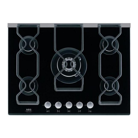
Description of the appliance 1. Hob top 2. Semi-rapid burner 3. Auxiliary burner 4. Ultra-rapid triple crown burner 5. Control knobs Instruction for the User Hob burners control knobs The symbols on the knobs mean that : there is no gas supply there is maximum gas supply there is minimum gas supply Lighting the burners... -
Page 6: Cleaning And Maintenance
Using the hob correctly To ensure maximum burner efficiency, it is strongly recommended that you use only pots and pans with a bottom fitting the size of the burner used, so that flame will not spread beyond the bottom of the vessel (see the table beside). -
Page 7: Something Not Working
Pan Supports To keep the pan supports in the correct position, they are mounted on metal pins located in the back of the hob. After cleaning the hob, ensure the pan supports are properly placed as shown in figure 3. The pan supports are dishwasher proof. -
Page 8: Service And Original Spare Parts
Service and original Spare Parts This appliance, before leaving the factory, has been tested and studied by many experts and specialists, in order to give you the best results. Any repair work which needs to be carried out should be done with the utmost care and attention. For this reason we recommend that for any problem you contact the dealer who sold it to you, or our nearest authorized Service Centre, specifying the nature of the problem, the appliance model (Mod.), the product number (Prod. -
Page 9: Technical Data
Gas Connection Choose fixed connections or use a flexible pipe in stainless steel. If using flexible metallic pipes, be careful they do not come in contact with mobile parts or they are not squeezed. Use the same attention when the hob is combinated with an oven. IMPORTANT - To ensure a correct operation, a saving of energy and the long-life of the appliance, the voltage Fig. - Page 10 Characteristics of burners NOMINAL POWER NOMINAL REDUCED POWER POWER TYPE OF BURNER INPUT NATURAL GAS LIQUID GAS 20 mbar 28-30/37 mbar Injectors Injectors marks marks G30 G31 100/mm 100/mm Auxiliary burner 0,33 0,095 Semi-rapid burner 0,45 0,181 Ultra-rapid triple crown burner 1,20 0,362 By-pass diameters...
-
Page 11: Electrical Connection
Electrical Connection The appliance is designed to be connected to 230 V monophase electricity supply. The connection must be carried out in compliance with the laws and regulations in force. Before the appliance is connected: 1) check that the main fuse and the domestic installation can support the load (see the rating label); 2) check that the power supply is properly earthed in compliance with the current rules;... -
Page 12: Adaptation To Different Types Of Gas
Adaptation to different types of gas Injectors replacement • Remove the pan supports. • Remove the burner's caps and crowns. • With a socket spanner 7 unscrew and remove the injectors (Fig. 6), and replace them with the ones required for the type of gas in use (see table “Characteristics of burners”). -
Page 13: Building In
Building In Fig. 8 - a These hobs can be inserted in a built-in kitchen unit whose depth is between 550 and 600 mm. The hobs dimensions are shown in Fig. 8-a. The edge of the cut out must have a minimum distance from the rear wall of 55 mm. -
Page 14: Possibilities For Insertion
Possibilities for insertion Kitchen unit with door Proper arrangements must be taken in designing the forniture unit, in order to avoid any contact with the bottom of the hob which can be heated when it is operated. The recommended solution is shown in Fig. - Page 15 Kitchen unit with oven The hob recess dimensions must comply the indication given in Figs. 11 and 12 and must be provided with brackets to allow a continuous supply of air. To avoid overhating, the building in should be carried out as shown in Figs. 13 e 14. The hob's electric connection and the oven's one must be carried out separately, both for safety reasons and to allow the oven to be easily taken off the unit.
- Page 16 AEG Hausgeräte GmbH Postfach 1036 D-90327 Nürnberg http://www.aeg.hausgeraete.de Copyright by AEG © From the Electrolux Group. The world’s No.1 choice. The Electrolux Group is the world’s largest producer of powered appliances for kitchen, cleaning and outdoor use. More than 55 million Electrolux Group products (such as refrigerators, cookers, washing machines, vacuum cleaners, chain saws and lawn mowers) are sold each year to a value of approx.